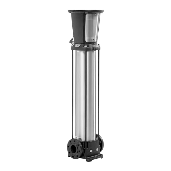
Grundfos CR 32 Service Instructions Manual
Hide thumbs
Also See for CR 32:
- Service manual (26 pages) ,
- Service instructions manual (20 pages) ,
- Installation and operating instructions manual (364 pages)
Advertisement
Quick Links
Advertisement

Summary of Contents for Grundfos CR 32
- Page 1 GRUNDFOS INSTRUCTIONS CR, CRN 32-90 Model B Standard model Service instructions...
-
Page 3: Service Tools
3. Service tools Pos. Designation For pos. Tool size Product No 18, 23 24 mm SV0122 Ring/open- 8 mm SV0273 end spanner 24 mm SV0122 Rubber SV0349 hammer 8 mm SV0032 3 mm Hexagon key 8 mm SV0032 8 mm SV0032 Torque .1-4 ft.-lbs./... - Page 4 4. Torques 6. Pump dismantling Position numbers refer to the drawings in section 11. Exploded Pos. Description Dimensions Torque views. Coupling guard 6.1 Motor 4.4 ft-lbs./6 Nm screws Coupling screws M10 x 25 mm 63 ft-lbs./85 Nm To prevent the motor from tipping over, hold it straight when using a lifting device.
- Page 5 6.3 Chamber stack 6.3.2 Dismantling chambers Depending on their construction, dismantle the chambers 6.3.1 Fitting chamber stack on the holder according to the instructions below. The symbols refer to section 1. Place the holder for dismantling and assembly in a vice and 10.
- Page 7 8.1.2 Assembly 8.2 Wear ring (pos. 49c) 1. Place neck ring (pos. 45) in cup (pos. 46). 8.2.1 Dismantling 2. Fit neck ring retainer (pos. 65) with the four driving dogs 1. Fit the holder on the impeller. The wear ring should come out pointing downwards.
- Page 9 Single chamber 9.3 Motor To prevent the motor from tipping over, hold it straight when using a lifting device. Caution Do not use the lifting eyes of the motor for lifting Fig. 17 Single chamber the entire pump and motor assembly. 1.
-
Page 12: Exploded Views
11. Exploded views Fig. 21 Exploded view, CR, CRN 32, model B... - Page 13 Fig. 22 Exploded view (detailed), CR, CRN 32, model B...


Need help?
Do you have a question about the CR 32 and is the answer not in the manual?
Questions and answers