
Related Manuals for IMI Norgren 34D Series

Summary of Contents for IMI Norgren 34D Series
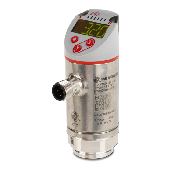
- Page 1 Electronic Pressure Sensor Operation manual for versions: 34D-xxxxx-DA1-xx 1x PNP/ 1x analogue (1x IO-Link, configurable)
-
Page 2: Table Of Contents
Electronic Pressure Sensor 34D Operation manual Content 1. Preliminary note 1.1 Symbols used 2 Safety information 3. Functions and features 3.1 Applications 4. Function 4.1 Communication, parameter setting, evaluation 4.2 Switching function 4.3 Analogue function 4.4 IO-Link 5. Installation 6. Electrical connection 7. - Page 3 Electronic Pressure Sensor 34D Operation manual 9.4.3 Set damping for the switching signal 9.4.4 Read min-/max values for the system pressure 9.4.5 Reset all parameters to factory setting 9.4.6 Set colour change of the display 9.4.7 Graphical depiction of the colour change of the display 10.
-
Page 4: Preliminary Note
Electronic Pressure Sensor 34D Operation manual Preliminary note 1.1 Symbols used ► Instructions > Reaction, result […] Designation of keys, buttons or indications → Cross-reference Important note, Non-compliance can result in malfunction or interference. Information Supplementary note 2. Safety instructions ... -
Page 5: Functions And Features
Electronic Pressure Sensor 34D Operation manual 3. Functions and features The device monitors the system pressure of machines and installations. 3.1 Applications Type of pressure: relative pressure Order number Measuring range Permissible Bursting pressure overpressure * Pressure sensors with internal thread G¼ 34D-P600…... -
Page 6: Function
Electronic Pressure Sensor 34D Operation manual Function The unit displays the current system pressure. It generates output signals according to the operating mode and the parameter setting. It moreover provides the process data via IO-Link. The unit is laid out for fully bidirectional communication. So, the following options are possible: o Remote display: reading and display of the current system pressure. -
Page 7: Analogue Function
Electronic Pressure Sensor 34D Operation manual 4.3 Analogue function OUT2 is an analogue output: [ou2] defines whether the set measuring range is provided as 4...20 mA ([ou2] = [I]) or as 0...10 V ([ou2] = [U]) 34D-xxxxx-DA1-AA: Analogue signal 4...20 mA / 0...10 V corresponds to the measuring range 0...10 bar. Negative pressure values cannot be represented via the analogue output for the indicated units. -
Page 8: Io-Link
Electronic Pressure Sensor 34D Operation manual 4.4 IO-Link General Information This unit has an IO-Link communication interface which requires an IO-Link-capable module (IO- Link master) for operation. The IO-Link interface enables direct access to the process and diagnostic data and provides the possibility to set the parameters of the unit during operation. -
Page 9: Electrical Connection
Electronic Pressure Sensor 34D Operation manual Electrical connection The unit must be connected by a qualified electrician. The national and international regulations for the installation of electrical equipment must be adhered to. Voltage supply according to EN 50178, SELV, PELV. ►... -
Page 10: Operating And Display Elements
Electronic Pressure Sensor 34D Operation manual Operating and display elements 1 to 8: Indicator LEDs LED 1 Switching status OUT1 (lights when output 1 is switched). LED 8 No function LED 2 - 7 System pressure in the indicated unit of measurement. 9: [Enter] button [●] - Selection of the parameters and acknowledgement of the parameter values. -
Page 11: Menu
Electronic Pressure Sensor 34D Operation manual Menu 8.1 Menu structure: Main menu 7503756000000050 05/2019... -
Page 12: Explanation Of The Menu
Electronic Pressure Sensor 34D Operation manual 8.2 Explanation of the menu 8.2.1 Explanation of the menu level 1 SPx/rPx Upper / lower limit value for system pressure at which OUT1 switches with hysteresis setting. SP1/rP1 is displayed if the parameter [Hno] or [Hnc] for OUT1 was set in the extended functions "EF"... -
Page 13: Parameter Setting
Electronic Pressure Sensor 34D Operation manual Parameter setting During parameter setting the unit remains in the operating mode. It continues to monitor with the existing parameters until the parameter setting has been completed. 9.1 Parameter setting in general Select parameter ►... - Page 14 Electronic Pressure Sensor 34D Operation manual Each parameter setting requires 3 steps: If [C.Loc] is displayed when an attempt is made to modify a parameter value, an IO-Link communication is active (temporary locking). If [S.Loc] is displayed, the sensor is permanently locked via software. This locking can only be removed using a parameter setting software.
- Page 15 Electronic Pressure Sensor 34D Operation manual Locking / unlocking The unit can be locked electronically to prevent unintentional settings. ► Make sure that the unit is in the normal operating mode. ► Press [▲] + [▼] simultaneously for 10 s. >...
-
Page 16: Configure Display (Optional)
Electronic Pressure Sensor 34D Operation manual 9.2 Configure display (optional) ► Select [Uni] and set the unit of measurement: [bAr], [mbAr], [MPA], [kPA], [PSI], [inHG] The selectable units of measurement depend on the respec-tive unit. ► Select [diS] and set the update rate and orientation of the display: [d1]: update of the measured values every 50 ms. -
Page 17: Define Switching Limits For The Hysteresis Function
Electronic Pressure Sensor 34D Operation manual 9.3.2 Define switching limits for the hysteresis function ► [ou1] / [ou2] must be set as [Hno] or [Hnc]. ► Select [SP1] / [SP2] and set the value at which the output is set. ►... -
Page 18: Read Min-/Max Values For The System Pressure
Electronic Pressure Sensor 34D Operation manual 9.4.4 Read min-/max values for the system pressure ► Select [HI] or [Lo] and briefly press [●]. [HI] = maximum value, [LO] = minimum value. Delete memory: ► Select [HI] or [LO]. ► Press and hold [▲] or [▼] until [----] is displayed. ► Briefly press [●]. 9.4.5 Reset all parameters to factory setting ►... -
Page 19: Graphical Depiction Of The Colour Change Of The Display
Electronic Pressure Sensor 34D Operation manual 9.4.7 Graphical depiction of the colour change of the display Display colour change with Display colour change for the parameters parameter[r1ou], mode hysteresis [G1ou] / [G1ou], mode hysteresis function function Measured value > switch point OUT1 Measured value >... -
Page 20: Operation
Electronic Pressure Sensor 34D Operation manual Display colour change with parameter [r-cF] Display colour change with parameter [G-cF] independent of OUT1 / OUT2. independent of OUT1 / OUT2 Measured value between cFL and cFH; Measured value between cFL and cFH; Display = red Display = green Colour change display green... -
Page 21: Read Set Parameters
Electronic Pressure Sensor 34D Operation manual Operation After power on, the unit is in the Run mode (= normal operating mode). It carries out its measurement and evaluation functions and provides output signals according to the set parameters. Operating indicators → 7 Operating and display elements. 10.1 Read set parameters ►... -
Page 22: Technical Data
Electronic Pressure Sensor 34D Operation manual Technical data 11.1 Setting ranges SP1 / SP2 rP1 / rP2 ΔP 34D-P600… 8700 8680 59,8 34D-P400… 5800 5780 39,8 34D-P250… 3620 3600 24,9 159,5 34D-P160… 14,5 2320 2313 7,25 0,05 15,9 0,05 99,5 34D-P100…... -
Page 23: Factory Setting
Electronic Pressure Sensor 34D Operation manual Factory setting Factory setting User setting / Comments SP1 / FH1 25% MEW* rP1 / FL1 23% MEW* 0,06 bAr / mbAr coLr MEW*** MAW** * = The indicated percentage of the final value of the measuring range (VMR) of the respective sensor (for PN7xx9 the percentage of the measuring span) is set. - Page 24 Electronic Pressure Sensor 34D Operation manual The data specified above only serve to describe the product. No statements concerning a certain condition or suitability for a certain application can be derived from our information. The given information does not release the user from the obligation of own judgement and verification.
Need help?
Do you have a question about the Norgren 34D Series and is the answer not in the manual?
Questions and answers