MSI MS-7236 Manual
Atx mainboard
Hide thumbs
Also See for MS-7236:
- User manual (88 pages) ,
- User manual (85 pages) ,
- User manual (108 pages)
Table of Contents
Advertisement
Advertisement
Table of Contents

Related Manuals for MSI MS-7236


Summary of Contents for MSI MS-7236
- Page 1 945PL Neo MS-7236 (v1.X) ATX Mainboard G52-M7236X1...
- Page 2 Notice 2 Shielded interface cables and A.C. power cord, if any, must be used in order to comply with the emission limits. VOIR LA NOTICE D’INSTALLATION AVANT DE RACCORDER AU RESEAU. Micro-Star International MS-7236...
-
Page 3: Copyright Notice
This device complies with Part 15 of the FCC Rules. Operation is subject to the following two conditions: (1) this device may not cause harmful interference, and (2) this device must accept any interference received, including interference that may cause undesired operation Copyright Notice The material in this document is the intellectual property of MICRO-STAR INTERNATIONAL. -
Page 4: Technical Support
Alternatively, please try the following help resources for further guidance. † Visit the MSI homepage & FAQ site for technical guide, BIOS updates, driver updates, and other information: http://www.msi.com.tw & http://www.msi. -
Page 5: Weee Statement
WEEE Statement... -
Page 8: Table Of Contents
CONTENTS FCC-B Radio Frequency Interference Statement ............ii Copyright Notice ....................... iii Technical Support ..................... iv Safety Instructions ....................iv WEEE Statement ......................v Chapter 1. Getting Started ................1-1 Mainboard Specifications ................1-2 Mainboard Layout ................... 1-4 Packing Contents .................... 1-5 Core Center .................... - Page 9 Front Panel Connectors: JFP1 / JFP2 ............ 2-17 Front USB Connectors: JUSB1 / JUSB2 ............2-18 Front Panel Audio Connector: JAUD1 ........... 2-18 Chassis Intrusion Switch Connector: JCI1 ........... 2-19 IrDA Infrared Module Header: JIR1 ............2-19 Serial Port Connector: JCOM1 .............. 2-19 Jumpers ......................
-
Page 10: Chapter 1. Getting Started
Getting Started Chapter 1. Getting Started Getting Started Thank you for choosing the 945PL Neo(MS-7236) v1.x ATX ® mainboard. The 945PL Neo mainboard is based on Intel 945PL and ® Intel ICH7 chipset for optimal system efficiency. Designed to fit the ®... -
Page 11: Mainboard Specifications
MS-7236 ATX Mainboard Mainboard Specifications † Supports Intel ® Pentium 4 LGA775 processors in LGA775 package. † Supports Intel Hyper-Threading Technology. (For the latest information about CPU, please visit http://www.msi.com.tw/program/ products/mainboard/mbd/pro_mbd_cpu_support.php) Chipset † Intel® 945PL chipset - Supports FSB 533/ 800MHz . - Page 12 Getting Started - 8 USB ports (Rear * 4/ Front * 4) - 1 RJ-45 LAN jack † Realtek RTL8110SB / RTC8110SC / RTL8100C(optional). - Supports 10 / 100 / 1000 Mb/s. - Compliane with PCI 2.2. - Supports ACPI Power Management. Audio †...
-
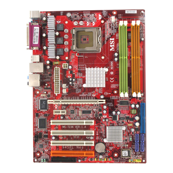
Page 13: Mainboard Layout
945PL Bottom: USB ports Line-In PWRFAN1 Li ne-Out T:RS-Out M:CS-Out B:SPDIFOut SYSFAN1 PCI_E1 RTL8110SB/8110SC PCI_E2 JCI1 JIR1 PCI1 Winbond W83627EHG PCI2 Intel ICH7 PCI3 JCOM1 JCD1 ALC850 BATT PCI4 JAUD1 JFP1 JFP2 JUSB2 JUSB1 FDD1 945PL Neo(MS-7236) v1.x ATX Mainboard... -
Page 14: Packing Contents
Getting Started Packing Contents SATA Cable *1 MSI Driver/Utility CD MSI motherboard (Optional) Standard Cable for IDE Devices Back IO Shield Power Cable (Optional) User’s Guide * The pictures are for reference only and may vary from the packing contents of the... -
Page 15: Core Center
MS-7236 ATX Mainboard Core Center Click on the Core Center icon in the main menu and the Core Center program will be enabled. CoreCenter is just like your PC doctor that can detect, view and adjust the PC hardware and system status during real time operation. -
Page 16: Left-Wing: Current System Status
Getting Started Left-wing: Current system status In the left sub-menu, you can configure the settings of FSB, Vcore, Memory Voltage and AGP Voltage by clicking the radio button next to each item and make it available (the radio button will be lighted as yellow when selected), use the “+” and “-” buttons to adjust, then click “OK”... -
Page 17: Chapter 2. Hardware Setup
Hardware Setup Chapter 2. Hardware Setup Hardware Setup This chapter tells you how to install the CPU, memory modules, and expansion cards, as well as how to setup the jumpers on the mainboard. Also, it provides the instructions on connecting the periph- eral devices, such as the mouse, keyboard, etc. -
Page 18: Quick Components Guide
MS-7236 ATX Mainboard Quick Components Guide CPU,p2-3 CPUFAN1 DIMM1~4,p2-7 JPW1, p2-9 Back Panel, p2-10 ATX1,p2-9 PWRFAN1 SYSFAN1, p2-14 PCI-E1~2, p2-21 IDE1, p2-15 JIR1, p-2-19 JCI1, p2-20 JBAT1, p2-20 PCI1~4, p2-22 JCOM1, p2-19 JCD1, p2-17 SATA1~4, p2-16 JFP2, p2-17 JAUD1, p2-18... -
Page 19: Central Processing Unit: Cpu
If you do not have the CPU cooler, contact your dealer to purchase and install them before turning on the computer. For the latest information about CPU, please visit http://www.msi.com.tw/ program/products/mainboard/mbd/pro_mbd_cpu_support.php. MSI Reminds You... -
Page 20: Cpu & Cooler Installation
MS-7236 ATX Mainboard CPU & Cooler Installation When you are installing the CPU, make sure the CPU has a cooler at- tached on the top to prevent overheating. If you do not have the cooler, contact your dealer to purchase and install them before turning on the computer. Meanwhile, do not forget to apply some silicon heat transfer compound on CPU before installing the heat sink/cooler fan for better heat dispersion. - Page 21 If not, package. take out the CPU with pure vertical motion and reinstall. MSI Reminds You... 1. Confirm if your CPU cooler is firmly installed before turning on your system. 2. Do not touch the CPU socket pins to avoid damaging.
- Page 22 MS-7236 ATX Mainboard 9. Press down the load lever lightly 10. Align the holes on the mainboard onto the load plate, and then se- with the heatsink. Push down the cure the lever with the hook under cooler until its four clips get retention tab.
-
Page 23: Memory
DDR2 memory module in the DDR2 slot (DIMM1~DIMM4). Otherwise, you are not able to boot up your system and your mainboard might be damaged. For the updated supporting memory modules, please visit http://www.msi. com.tw/program/products/mainboard/mbd/pro_mbd_trp_list.php. DIMM1,2 and DIMM3,4 (from left (Green) to right(Orange)) Channel A (DIMM1 &... -
Page 24: Installing Ddr2 Modules
MS-7236 ATX Mainboard Installing DDR2 Modules The DDR2 DIMM has only one notch on the center of module. The module will only fit in the right orientation. Insert the DIMM memory module vertically into the DIMM slot. Then push it in until the golden finger on the memory module is deeply inserted in the socket. -
Page 25: Power Supply
JPW1 Pin Definition SIGNAL JPW1 MSI Reminds You... 1. These two connectors connect to the ATX power supply and have to work together to ensure stable operation of the mainboard. 2. Power supply of 350 watts (and above) is highly recommended for system stability. -
Page 26: Mouse/Keyboard Connector
MS-7236 ATX Mainboard Back Panel The back panel provides the following connectors: RS-Out L-In Parallel M ouse USB Ports CS-Out COM Port L-Out Keyboard SPDIF Mouse/Keyboard Connector ® The mainboard provides a standard PS/2 mouse/keyboard mini DIN connector ® ®... -
Page 27: Serial Port Connector: Com Port
Hardware Setup Serial Port Connector: COM Port The mainboard offers one 9-pin male DIN connector COM Port. It’s a 16550A high speed communication port that send/receive/ 16 bytes FIFOs. You can attach a serial mouse or other serial device directly to it. Pin Definition SIGNAL DESCRIPTION... -
Page 28: Lan (Rj-45) Jack
MS-7236 ATX Mainboard LAN (RJ-45) Jack The mainboard provides 1 standard RJ-45 jack for connection to single Local Area Network (LAN). This LAN enables data to be transferred at 1000Mbps, 100Mbps or 10Mbps. You can connect a network cable to it. -
Page 29: Parallel Port Connector: Lpt1
Hardware Setup Parallel Port Connector: LPT1 The mainboard provides a 25-pin female centronic connector as LPT. A parallel port is a standard printer port that supports Enhanced Parallel Port (EPP) and Ex- tended Capabilities Parallel Port (ECP) mode. Pin Definition SIGNAL DESCRIPTION STROBE... -
Page 30: Floppy Disk Drive Connector: Fdd1
MS-7236 ATX Mainboard Connectors The mainboard provides connectors to connect to FDD, IDE HDD, case, LAN, and USB Ports. Floppy Disk Drive Connector: FDD1 The mainboard provides a standard floppy disk drive connector that supports 360K, 720K, 1.2M, 1.44M and 2.88M floppy disk types. -
Page 31: Hard Disk Connector: Ide1
IDE1 can connect a Master and a Slave drive. You must configure second hard drive to Slave mode by setting the jumper accordingly. MSI Reminds You... If you install two hard disks on cable, you must configure the second drive to Slave mode by setting its jumper. Refer to the hard disk documentation supplied by hard disk vendors for jumper setting instructions. -
Page 32: Serial Ataii Connectors Controlled By Intel Ich7: Sata1~Sata4
MS-7236 ATX Mainboard Serial ATAII Connectors controlled by Intel ICH7: SATA1~SATA4 The SouthBridge of this mainboard is Intel ICH7 which supports four serial ATAII connectors SATA1~SATA4. SATA1~SATA4 are dual high-speed Serial ATAII interface ports. Each supports Serial ATAII data rates of 300MB/s. -
Page 33: Cd-In Connector: Jcd1
Hardware Setup CD-In Connector: JCD1 The connector is for CD-ROM audio connector. JCD1 Front Panel Connectors: JFP1 / JFP2 The mainboard provides two front panel connectors for electrical connection ® to the front panel switches and LEDs. JFP1 is compliant with Intel Front Panel I/O Connectivity Design Guide. -
Page 34: Front Usb Connectors: Jusb1 / Jusb2
MS-7236 ATX Mainboard Front USB Connectors: JUSB1 / JUSB2 The mainboard provides two standard USB 2.0 pin headers JUSB1 & JUSB2. USB 2.0 technology increases data transfer rate up to a maximum throughput of 480Mbps, which is 40 times faster than USB 1.1, and is ideal for connecting high- speed USB interface peripherals such as USB HDD, digital cameras, MP3 players, printers, modems and the like. -
Page 35: Chassis Intrusion Switch Connector: Jci1
Hardware Setup IrDA Infrared Module Header: JIR1 The connector allows you to connect to IrDA Infrared module. You must con- figure the setting through the BIOS setup to use the IR function. JIR1 is compliant with ® Intel Front Panel I/O Connectivity Design Guide. Pin Definition JIR1 Signal... -
Page 36: Jumpers
MS-7236 ATX Mainboard Jumpers The motherboard provides the following jumpers for you to set the computer’s function. This section will explain how to change your motherboard’s function through the use of jumpers. Clear CMOS Jumper: JBAT1 There is a CMOS RAM on board that has a power supply from external battery to keep the system configuration data. -
Page 37: Slots
Hardware Setup Slots The mainboard provides a PCI Express x16 slot, a PCI Express x1 slot and four 32-bit PCI bus slots. PCI Express Slots The PCI Express slots, as a high-bandwidth, low pin count, serial, intercon- nect technology, support Intel highest performance desktop platforms utilizing the Intel Pentium 4 processor with HT Technology. -
Page 38: Pci (Peripheral Component Interconnect) Slots
MS-7236 ATX Mainboard PCI (Peripheral Component Interconnect) Slots The PCI slots allow you to insert the expansion cards to meet your needs. When adding or removing expansion cards, make sure that you unplug the power supply first. Meanwhile, read the documentation for the expansion card to make any necessary hardware or software settings for the expansion card, such as jumpers, switches or BIOS configuration. -
Page 39: Chapter 3. Bios Setup
SETUP. ² You want to change the default settings for customized features. MSI Reminds You... 1. The items under each BIOS category described in this chapter are under continuous update for better system performance. Therefore, the description may be slightly different from the latest BIOS and should be held for reference only. -
Page 40: Entering Setup
MS-7236 ATX Mainboard Entering Setup Power on the computer and the system will start POST (Power On Self Test) process. When the message below appears on the screen, press <DEL> key to enter Setup. Also you can press <F11> to enter boot menu. - Page 41 BIOS Setup MSI Reminds You... The items under each BIOS category described in this chapter are under continuous update for better system performance. Therefore, the description may be slightly different from the latest BIOS and should be held for reference only.
-
Page 42: The Main Menu
MS-7236 ATX Mainboard The Main Menu Once you enter AwardBIOS CMOS Setup Utility, the Main Menu will appear on the screen. Use arrow keys to move among the items and press <Enter> to enter the sub-menu. Standard CMOS Features Use this menu for basic system configurations, such as time, date etc. - Page 43 BIOS Setup Load Fail-Safe Defaults Use this menu to load the default values set by the BIOS vendor for stable system performance. Load Optimized Defaults Use this menu to load the default values set by the mainboard manufacturer specifically for optimal performance of the mainboard. BIOS Setting Password Use these two menus to set the passwords for BIOS.
-
Page 44: Standard Cmos Features
MS-7236 ATX Mainboard Standard CMOS Features The items in Standard CMOS Features Menu includes some basic setup items. Use the arrow keys to highlight the item and then use the <+> or <-> keys to select the value you want in each item. - Page 45 BIOS Setup Type This item allows you to select how to define the HHDD parameters. LBA/Large Mode This item allows you to enable or disable the LBA (Logical Block Address, the logical block size in hard disk) mode. Setting options: [Auto], [Disabled]. Block (Multi-Sector Transfer) Select Auto for a hard disk performance.
-
Page 46: Advanced Bios Features
MS-7236 ATX Mainboard Advanced BIOS Features Quick Boot Setting the item to [Enabled] allows the system to boot within 5 seconds since it will skip some check items. Available options: [Enabled], [Disabled]. CPU Configuration Press <Enter> to enter the sub-menu. - Page 47 BIOS Setup Virtualization Technology (Only for the CPU with dual core) Virtualization Technology will allow a platform to run multiple operating systems and applications in independent partitions. With virtualization, one computer sys- tem can function as multiple “virtual” systems. With enhancements to Intel’s vari- ous platforms, Intel Virtualization Technology can improve the robustness and performance of today’s software-only solutions.Settings: [Enabled], [Disabled].
- Page 48 MS-7236 ATX Mainboard MPS Confuration This field allows you to select which MPS (Multi-Processor Specification) version to be used for the operating system. You need to select the MPS version supported by your operating system. To find out which version to use, consult the vendor of your operating system.
-
Page 49: Advanced Chipset Features
BIOS Setup Advanced Chipset Features MSI Reminds You... Change these settings only if you are familiar with the chipset. DRAM Frequency Use this field to configure the clock frequency of the installed DRAM. Setting options: [Auto], [400], [533]. Configure DRAM Timing by SPD Selects whether DRAM timing is controlled by the SPD (Serial Presence Detect) EEPROM on the DRAM module. -
Page 50: Integrated Peripherals
MS-7236 ATX Mainboard Integrated Peripherals USB Functions This setting is used to enable/disable the onboard USB host controller. Setting options: [Disabled], [Enabled]. USB 2.0 Controller Set to [Enabled] if you need to use any USB 2.0 device in the operating system that does not support or have any USB 2.0 driver installed, such as DOS and SCO Unix. - Page 51 BIOS Setup IDE Configuration Press <Enter> to enter the sub-menu: PCI IDE BusMaster This item allows you to enable/ disable the PCI IDE busmaster. Setting options: [Disabled], [Enabled]. ATA(PI) 80Pin Cable Detectio This item allows you to select the mechanism for detecting 80Pin ATA(PI) Cable. Setting options: [Host &...
- Page 52 MS-7236 ATX Mainboard Serial Port1/2 Address These items specify the base I/O port addresses of the onboard Serial Port 1 . Selecting [Auto] allows BIOS to automatically determine the correct base I/O port address. Settings: [3F8/IRQ4], [2F8/IRQ3], [3E8/IRQ4], [2E8/IRQ3] and [Disabled].
-
Page 53: Power Management Features
BIOS Setup Power Management Features MSI Reminds You... S3-related functions described in this section are available only when your BIOS supports S3 sleep mode. ACPI Function This item is to activate the ACPI (Advanced Configuration and Power Management Interface) Function. If your operating system is ACPI-aware, such as Windows 98SE/ 2000/ME/XP, select [Enabled]. - Page 54 MS-7236 ATX Mainboard Re-Call VGA BIOS from S3 When ACPI Standby State is set to [S3/STR], users can select the options in this field. Selecting [Yes] allows BIOS to call VGABIOS to initialize the VGA card when system wakes up (resumes) from S3 sleep state. The system resume time is short- ened when you disable the function, but system will need an AGP driver to initialize the VGA card.
- Page 55 BIOS Setup Specific Key for PowerOn This item is available when Keyboard Wakeup is enabled. This controls how and whether the keyboard is able to power on the system. Press Enter, and then you must press a key for power on the system. Mouse WakeUp This setting determines whether the system will be awakened from what power saving modes when input signal of the mouse is detected.
-
Page 56: Pci/Pnp Resource Management
MS-7236 ATX Mainboard PCI/PNP Resource Management This section describes configuring the PCI bus system and PnP (Plug & Play) feature. PCI, or Peripheral Component Interconnect, is a system which allows I/O devices to operate at speeds nearing the speed the CPU itself uses when communicating with its special components. - Page 57 BIOS Setup RQ Resources Setup The items are adjustable only when Resources Controlled By is set to Manual. Press <Enter> and you will enter the sub-menu of the items. IRQ Resources list IRQ 3/4/5/7/9/10/11/12/14/15 for users to set each IRQ a type depending on the type of device using the IRQ.
-
Page 58: H/W Monitor
MS-7236 ATX Mainboard H/W Monitor This section shows the status of your CPU, fan, overall system status, etc. Monitor function is available only if there is hardware monitoring mechanism onboard. Chassis Intrusion The field enables or disables the feature of recording the chassis intrusion status and issuing a warning message if the chassis is once opened. -
Page 59: Cell Menu
BIOS Setup Cell Menu The items here includes some important settings of CPU and PCI functions. MSI Reminds You... Change these settings only if you are familiar with the chipset. Adjust DDR Voltage (V) Adjusting the DDR voltage can increase the DDR speed. Any changes made to this setting may cause a stability issue, so changing the DDR voltage for long-term purpose is NOT recommended. - Page 60 MS-7236 ATX Mainboard Spread Spectrum When the motherboard’s clock generator pulses, the extreme values (spikes) of the pulses creates EMI (Electromagnetic Interference). The Spread Spectrum function reduces the EMI generated by modulating the pulses so that the spikes of the pulses are reduced to flatter curves.
- Page 61 BIOS Setup MSI Reminds You... 1. Even though the Dynamic Overclocking Technology is more stable than manual overclocking, basically, it is still risky. We suggest user to make sure that your CPU can afford to overclock regularly first. If you find the PC appears to be unstable or reboot incidentally, it's better to disable the Dynamic Overclocking or to lower the level of overclocking options.
-
Page 62: Load Fail-Safe/Optimized Defaults
MS-7236 ATX Mainboard Load Fail-Safe/Optimized Defaults The two options on the main menu allow users to restore all of the BIOS settings to the default Fail-Safe or Optimized values. The Optimized Defaults are the default values set by the mainboard manufacturer specifically for optimal performance of the mainboard. -
Page 63: Bios Setting Password
BIOS Setup BIOS Setting Password When you select this functions, a message as below will appear on the screen: Type the password, up to six characters in length, and press <Enter>. The password typed now will replace any previously set password from CMOS memory. You will be prompted to confirm the password. -
Page 64: Chapter 4. Introduction To Realtek Alc850
Introduction to Realtek ALC850 The mainboard is equipped with Realtek ALC850 chip, which provides support for 8-channel audio output, including 2 Front, 2 Rear, 1 Center and 1 Subwoofer channel. ALC850 allows the board to attach 2, 4, 6 or 8 speakers for better surround sound effect. -
Page 65: Installing The Audio Driver
MS-7236 ATX Mainboard Installing the Audio Driver You need to install the driver for Realtek ALC850 codec to function properly before you can get access to 2-, 4-, 6- or 8- channel audio operations. Follow the procedures described below to install the drivers for different operating systems. - Page 66 Introduction to Realtek ALC850 3. Click Next to install the AC’97 Audio software. Click here 4. Click Finish to restart the system. Select this option Click here 4 - 3...
-
Page 67: Software Configuration
MS-7236 ATX Mainboard Software Configuration After installing the audio driver, you are able to use the 2-, 4-, 6- or 8- channel audio feature now. Click the audio icon from the system tray at the lower-right corner of the screen to activate the AC97 Audio Configuration. It is also available to enable the audio driver by clicking the Sound Effect Manager from the Control Panel. -
Page 68: Sound Effect
Introduction to Realtek ALC850 Sound Effect Here you can select a sound effect you like from the Environment list. Edit You may also edit the properties for an environment as you wish by clicking the “Edit” button, then just scroll the bar in the bottom for each property to adjust. 4 - 5... - Page 69 MS-7236 ATX Mainboard You may choose the provided sound effects, and the equalizer will adjust automatically. If you like, you may also load an equalizer setting or make an new equalizer setting to save as an new one by using the “Load EQ Setting” and “Save Preset”...
-
Page 70: Speaker Configuration
Introduction to Realtek ALC850 Speaker Configuration In this tab, you can easily configure your multi-channel audio function and speakers. 1. First you have to select the audio configuration below which is identical to the audio jack on your mainboard. In this model it uses Realtek ALC850 codec which supports 8-channel S/PDIF, therefore you should choose 8CH-S/PDIF (Optical &... - Page 71 MS-7236 ATX Mainboard Select the speaker by clicking it to test its functionality. The one you select will light up and make testing sound. If any speaker fails to make sound, then check whether the cable is inserted firmly to the connector or replace the bad speakers with good ones.
-
Page 72: Hrtf Demo
Introduction to Realtek ALC850 HRTF Demo In this tab you may adjust your HRTF (Head Related Transfer Functions) 3D positional audio before playing 3D audio applications like gaming. You may also select different environment to choose the most suitable environment you like. 4 - 9... -
Page 73: General
MS-7236 ATX Mainboard General In this tab it provides some information about this AC97 Audio Configuration utility, including Audio Driver Version, DirectX Version, Audio Controller & AC97 Codec. You may also select the language of this utility by choosing from the Language list. -
Page 74: Spdif
Introduction to Realtek ALC850 SPDIF In this tab it provides options about SPDIF-Out for you to configure. † No Output: With this option, there is no S/PDIF output signal while playing analog and digital audio. † Output digital only: With this option, only digital audio will be allowed to play via SPDIF out while playing analog and digital audio. -
Page 75: Using 2-, 4-, 6- & 8- Channel Audio Function
MS-7236 ATX Mainboard Using 2-, 4-, 6- & 8- Channel Audio Function Connecting the Speakers When you have set the Multi-Channel Audio Function mode properly in the software utility, connect your speakers to the correct phone jacks in accordance with the setting in software utility. - Page 76 Introduction to Realtek ALC850 n 4-Channel Mode for 4-Speaker Output Description: Connect two speakers to back panel’s Line Out connector and two speakers to the real-chan- 4-Channel Analog Audio Output nel Line Out connector. Line In Line Out (Front channels) Line Out (Rear channels) Line Out (Center and Subwoofer channel, but no functioning in this mode) Optical SPDIF jack...
- Page 77 MS-7236 ATX Mainboard n 6-Channel Mode for 6-Speaker Output Description: Connect two speakers to back panel’s Line Out connector, two speakers to the rear-channel 6-Channel Analog Audio Output and two speakers to the cen- ter/subwoofer-channel Line Out connectors. Line In...
- Page 78 Introduction to Realtek ALC850 n 8-Channel Mode for 8-Speaker Output Description: Connect two speakers to back panel’s Line Out connector, two speakers to the rear-channel, 8-Channel Analog Audio Output two speakers to the center/ subwoofer-channel Line Out connectors, and two speakers Line Out (Side channels) to the side-channel Line Out Line Out (Front channels)
Need help?
Do you have a question about the MS-7236 and is the answer not in the manual?
Questions and answers