Table of Contents
Advertisement
Advertisement
Table of Contents

Related Manuals for MSI P965 Neo


Summary of Contents for MSI P965 Neo
- Page 1 P965 Neo Series MS-7235 (V1.X) Mainboard G52-72351X1...
-
Page 2: Copyright Notice
If a problem arises with your system and no solution can be obtained from the user’s manual, please contact your place of purchase or local distributor. Alternatively, please try the following help resources for further guidance. Visit the MSI website for FAQ, technical guide, BIOS updates, driver updates, and other information: http://www.msi.com.tw/program/service/faq/ faq/esc_faq_list.php... -
Page 3: Safety Instructions
Safety Instructions Always read the safety instructions carefully. Keep this User’s Manual for future reference. Keep this equipment away from humidity. Lay this equipment on a reliable flat surface before setting it up. The openings on the enclosure are for air convection hence protects the equip- ment from overheating. - Page 4 FCC-B Radio Frequency Interference Statement T h is eq uip men t h as been tested and found to c omply with the limits for a Class B digital device, pursuant to Part 15 of the FCC Rules. These limits are designed to provide reasonable protection against harmful interference in a residential installation.
- Page 5 WEEE (Waste Electrical and Electronic Equipment) Statement...
-
Page 8: Table Of Contents
Chapter 1 Getting started ..................1-1 Mainboard Specifications ................... 1-2 Mainboard Layout ....................1-4 Packing Checklist ....................1-4 MSI Special Feature .................... 1-6 Quick Components Guide ..................2-2 Chapter 2 Hardware Setup ................... 2-1 CPU (Central Processing Unit) ................2-2 Introduction to LGA 775 CPU .............. - Page 9 Chapter 3 BIOS Setup ..................... 3-1 Entering Setup ..................... 3-2 The Main Menu ..................... 3-4 Standard CMOS Features ................... 3-6 Advanced BIOS Features ................... 3-8 Advanced Chipset Features ................3-10 Integrated Peripherals ..................3-13 Power Management Setup ................3-14 PNP/PCI Configurations ..................3-19 H/W Monitor ......................
-
Page 10: Chapter 1 Getting Started
Getting Started Chapter 1 Getting Started Thank you for choosing the P965 Neo Series (MS-7235 v1.X) ATX mainboard. The P965 Neo Series mainboards are based on Intel ® P965 & ICH8 chipsets for optimal system efficiency. Designed to fit the advanced Intel ®... -
Page 11: Mainboard Specifications
Processor Support - Intel Celeron/Pentium 4, Pentium D, Core 2 series processors in ® LGA775 package (For the latest information about CPU, please visit http://www.msi. com.tw/program/products/mainboard/mbd/)pro_mbd_cpu_support. Supported FSB - 1066/ 800/ 533 MHz Chipset - North Bridge: Intel P965 chipset ®... -
Page 12: Getting Started
Getting Started Connectors Back Panel - 1 PS/2 mouse port - 1 PS/2 keyboard port - 1 serial port (COM1) - 1 parallel port supporting SPP/EPP/ECP mode - 4 USB 2.0 ports - 1 LAN jack (10/100/1000) - 6 flexible audio jacks On-Board Pinheaders - 1 IrDA pinheader - 1 front audio pinheader... -
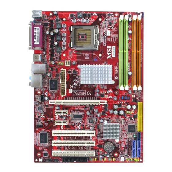
Page 13: Mainboard Layout
J US B 2 J US B 3 J F P1 J F P 2 SY S _ FA N 1 JC I 1 J CO M 1 J IR 1 F DD1 P965 Neo Series (MS-7235 v1.X) ATX Mainboard... -
Page 14: Packing Checklist
Getting Started Packing Checklist MSI Driver/Utility CD SATA Cable MSI motherboard Standard Cable for Power Cable IDE Devices Back IO Shield User’s Guide * The pictures are for reference only. Your packing contents may vary depending on the model you purchased. -
Page 15: Msi Special Feature
M S-7235 M ainboard MSI Special Feature The Core Center is a new utility you can find in the CD-ROM disk. The utility is just like your PC doctor that can detect, view and adjust the PC hardware and system status during real time operation. - Page 16 Getting Started Left-wing: Current system status In the left sub-menu, you can configure the settings of FSB, Vcore, Memory Voltage and AGP Voltage by clicking the radio button next to each item and make it available (the radio button will be lighted as yellow when selected), use the “+” and “-” buttons to adjust, then click “OK”...
- Page 17 Hardware Setup Chapter 2 Hardware Setup This chapter provides you with the information about hardware setup procedures. While doing the installation, be careful in holding the components and follow the installation procedures. For some components, if you install in the wrong orientation, the components will not work properly.
-
Page 18: Quick Components Guide
M S-7235 M ainboard Quick Components Guide... -
Page 19: Chapter 2 Hardware Setup
W hen you are installing the CPU, make sure to install the cooler to prevent overheating. If you do not have the CPU cooler, contact your dealer to purchase and install them before turning on the computer. For the latest information about CPU, please visit http://www.msi.com.tw/program/ products/mainboard/mbd/pro_mbd_cpu_support.php. Important 1. -
Page 20: Cpu & Cooler Installation
M S-7235 M ainboard CPU & Cooler Installation W hen you are installing the CPU, make sure the CPU has a cooler at- tached on the top to prevent overheating. If you do not have the cooler, contact your dealer to purchase and install them before turning on the computer. Meanwhile, do not forget to apply some silicon heat transfer compound on CPU before installing the heat sink/cooler fan for better heat dispersion. - Page 21 Hardware Setup Important 1. Confirm if your CPU cooler is firmly installed before turning on your system. 2. Do not touch the CPU socket pins to avoid damaging. 3. The availability of the CPU land side cover depends on your CPU packing. 5.
- Page 22 M S-7235 M ainboard 9. Press down the load lever lightly 10. Align the holes on the mainboard onto the load plate, and then se- with the heatsink. Push down the cure the lever with the hook under c ooler u nti l i ts f ou r c lip s g et retention tab.
-
Page 23: Dual Channel Memory Population Rules
Hardware Setup Memory The mainboard provides four 240-pin non-ECC DDRII 800/667/533 DIMM slots and supports up to 8GB system memory. For more information on compatible components, please visit http://www.msi.com.tw/ program/products/mainboard/mbd/pro_mbd_trp_list.php. DDRII 240-pin, 1.8V 64x2=128 pin 56x2=112 pin Single-Channel: All DIMMs in GREEN Dual-Channel: Channel A in GREEN;... -
Page 24: Installing Ddrii Modules
M S-7235 M ainboard Installing DDRII Modules 1. The memory module has only one notch on the center and will only fit in the right orientation. 2. Insert the memory module vertically into the DIMM slot. Then push it in until the golden finger on the memory module is deeply inserted in the DIMM slot. -
Page 25: Power Supply
Hardware Setup Power Supply ATX 24-Pin Power Connector: ATX1 This connector allows you to connect an ATX 24-pin power supply. To connect the ATX 24-pin power supply, make sure the plug of the pin 13 power supply is inserted in the proper orientation and the pins are aligned. -
Page 26: Back Panel
M S-7235 M ainboard Back Panel L-In RS-Out CS-Out L-Out Parallel Port M ou se USB Ports SS-Out Keyboard Serial Port M ouse/Keyboard Connector The standard PS/2 ® mouse/keyboard DIN connector is for a PS/2 ® mouse/keyboard. Parallel Port Connector A parallel port is a standard printer port that supports Enhanced Parallel Port (EPP) and Extended Capabilities Parallel Port (ECP) mode. - Page 27 Hardware Setup for external CD player, tapeplayer or other audio devices. Green audio jack - Line Out, is a connector for speakers or headphones. Pink audio jack - Mic In, is a connector for microphones. Black audio jack - Rear-Surround Out in 5.1/ 7.1 channel mode. Orange audio jack - Center/ Subwoofer Out in 5.1/ 7.1 channel mode.
-
Page 28: Connectors
M S-7235 M ainboard Connectors Floppy Disk Drive Connector: FDD1 This standard FDD connector supports 360K, 720K, 1.2M, 1.44M and 2.88M floppy disk types. FDD1 Hard Disk Connector: IDE1 The mainboard provides a one-channel Ultra ATA 133 bus Master IDE controller that supports PIO mode 0~4, Bus Master, and Ultra DMA 66/100/133 function. -
Page 29: Serial Ataii Connectors: Sata1/3/4/67
Hardware Setup Serial ATAII Connectors: SATA1/3/4/6/7 SATA1/4/3/6/7 are high-speed Serial ATAII interface ports. Each supports 2 genera- tion serial ATA data rates of 300MB/s and is fully compliant with Serial ATA 2.0 specifications. Each Serial ATAII connector can connect to 1 SATA device. SATA1 SATA1/4/3/6/7 Pin Definition SATA1... -
Page 30: Chassis Intrusion Switch Connector: Jci1
M S-7235 M ainboard Fan Power Connectors: CPU_FAN1, NB_FAN1, SYS_FAN1 The fan power connectors support system cooling fan with +12V. W hen connecting the wire to the connectors, always take note that the red wire is the positive and should be connected to the +12V, the black wire is Ground and should be connected to GND. -
Page 31: Cd-In Connector: Jcd1
Hardware Setup CD-In Connector: JCD1 This connector is provided for CD-ROM audio. JCD1 Front Panel Audio Connector: JAUD1 The JAUD1 front panel audio connector allows you to connect the front panel audio and is compliant with Intel Front Panel I/O Connectivity Design Guide. ®... -
Page 32: Front Panel Connectors: Jfp1/Jfp2
M S-7235 M ainboard Front Panel Connectors: JFP1/JFP2 The mainboard provides two front panel connectors for electrical connection to the front panel switches and LEDs. The JFP1 is compliant with Intel Front Panel I/O ® Connectivity Design Guide. Power Power Speaker Switch JFP2... -
Page 33: Front Usb Connectors: Jusb1, Jusb2, Jusb3
Hardware Setup Front USB Connectors: JUSB1, JUSB2, JUSB3 The mainboard provides three USB 2.0 pinheaders (optional USB 2.0 bracket available) that are compliant with Intel I/O Connectivity Design Guide. USB 2.0 technology ® increases data transfer rate up to a maximum throughput of 480Mbps, which is 40 times faster than USB 1.1, and is ideal for connecting high-speed USB interface peripherals such as USB HDD, digital cameras, M P3 players, printers, mo- dems and the like. -
Page 34: Irda Infrared Module Header: Jir1
M S-7235 M ainboard IrDA Infrared Module Header: JIR1 The connector allows you to connect to IrDA Infrared module. You must configure the setting through the BIOS setup to use the IR function. JIR1 is compliant with Intel ® Front Panel I/O Connectivity Design Guide. Pin Definition Signal JIR1... -
Page 35: Jumpers
Hardware Setup Jumpers Clear CMOS Jumper: JBAT1 There is a CMOS RAM onboard that has a power supply from external battery to keep the data of system configuration. With the CMOS RAM, the system can automatically boot OS every time it is turned on. If you want to clear the system configuration, set the JCMOS1 (Clear CMOS Jumper ) to clear data. -
Page 36: Slots
M S-7235 M ainboard Slots PCI (Peripheral Component Interconnect) Express Slots PCI Express architecture provides a high performance I/O infrastructure for Desktop Platforms with transfer rates starting at 2.5 Giga transfers per second over a PCI Express x1 lane for Gigabit Ethernet, TV Tuners, 1394 controllers, and general pur- pose I/O. -
Page 37: Pci Interrupt Request Routing
Hardware Setup PCI Interrupt Request Routing The IRQ, acronym of interrupt request line and pronounced I-R-Q, are hardware lines over which devices can send interrupt signals to the microprocessor. The PCI IRQ pins are typically connected to the PCI bus pins as follows: Order 1 Order 2 Order 3... -
Page 38: Chapter 3 Bios Setup
BIOS Setup Chapter 3 BIOS Setup This chapter provides information on the BIOS Setup program and allows you to configure the system for optimum use. You may need to run the Setup program when: ² An error message appears on the screen during the system booting up, and requests you to run SETUP. -
Page 39: Entering Setup
M S-7235 M ainboard Entering Setup Power on the computer and the system will start POST (Power On Self Test) process. W hen the message below appears on the screen, press <DEL> key to enter Setup. Press DEL to enter SETUP If the message disappears before you respond and you still wish to enter Setup, restart the system by turning it OFF and On or pressing the RESET button. -
Page 40: Control Keys
BIOS Setup Control Keys Move to the previous item < > Move to the next item < > Move to the item in the left hand < > Move to the item in the right hand < > Select the item <Enter>... -
Page 41: The Main Menu
M S-7235 M ainboard The Main Menu Standard CM OS Features Use this menu for basic system configurations, such as time, date etc. Advanced BIOS Features Use this menu to setup the items of AWARD special enhanced features. ® Advanced Chipset Features Use this menu to change the values in the chipset registers and optimize your system’s performance. - Page 42 BIOS Setup Load Fail-Safe Defaults Use this menu to load the default values set by the mainboard manufacturer. Load Optimized Defaults Use this menu to load the default values set by the mainboard manufacturer specifi- cally for optimal performance of the mainboard. BIOS Setting Password Use this menu to set the password for BIOS.
-
Page 43: Standard Cmos Features
M S-7235 M ainboard Standard CMOS Features The items in Standard CMOS Features Menu includes some basic setup items. Use the arrow keys to highlight the item and then use the <+> or <-> keys to select the value you want in each item. Date (mm:dd:yy) This allows you to set the system to the date that you want (usually the current date). - Page 44 BIOS Setup IDE Primary/Secondary M aster/Slave Selecting “manual” lets you set the remaining fields on this screen. Selects the type of fixed disk. “User Type” will let you select the number of cylinders, heads, etc. Access M ode Choose the access mode forthis hard disk Halt On The setting determines whether the system will stop if an error is detected at boot.
-
Page 45: Advanced Bios Features
M S-7235 M ainboard Advanced BIOS Features CPU Feature Press <Enter> to enter the sub-menu: (NOTE: The Shown items depend on the CPU you install) Set Limit CPUID MaxVal to 3 [enabled] The processor will limit the maximum CPUID input value to 03h when queried, even if the processor supports a higher CPUID input value. - Page 46 BIOS Setup Hard Disk Boot Priority Press [Enter] to enter a sub menu which shows every current hard drive installed. Use [PageUp] or [PageDown] key to select the first boot hard disk. Boot Sequence Press <Enter> to enter the sub-menu: 1st/2nd/3rd Boot Device The items allow you to set the sequence of boot devices where BIOS attempts to load the disk operating system.
-
Page 47: Advanced Chipset Features
M S-7235 M ainboard Advanced Chipset Features Important Change these settings only if you are familiar with the chipset. DRAM Timing The value in this field depends on performance parameters of the installed memory chips (DRAM). Do not change the value from the factory setting unless you install new memory that has a different performance rating than the original DRAMs. - Page 48 BIOS Setup M in RAS# Active Time (Tras) This setting determines the time RAS takes to read from and write to a memory cell. M emory Hole In order to improve performance, certain space in memory can be reserved for ISA peripherals.
-
Page 49: Integrated Peripherals
M S-7235 M ainboard Integrated Peripherals On-Chip ATA Devices Press <Enter> to enter the sub-menu: IDE HDD Block Mode Block mode is also called block transfer, multiple commands, or multiple sector read/write. If your IDE hard drive supports block mode (most new drives do), select [Enabled] for automatic detection of the optimal number of block read/writes per sector the drive can support. - Page 50 BIOS Setup IDE\RAID Control This item is available for you to enable/disable the onboard IDE RAID function. USB Controller This setting is used to enable/disable the onboard USB host controller. USB Keyboard Support Select Enabled if your system contains a Universal Serial Bus (USB) controller and you have a USB keyboard.
- Page 51 M S-7235 M ainboard Parallel Port There is a built-in parallel port on the on-board Super I/O chipset that provides Standard, ECP, and EPP features. Parallel Port M ode [SPP] Standard Parallel Port [EPP] Enhanced Parallel Port [ECP] Extended Capability Port [ECP + EPP] Extended Capability Port + Enhanced Parallel Port To operate the onboard parallel port as Standard Parallel Port only, choose [SPP].
-
Page 52: Power Management Setup
BIOS Setup Power Management Setup Important S3-related functions described in this section are available only when your BIOS supports S3 sleep mode. ACPI Function This item is to activate the ACPI (Advanced Configuration and Power Management Interface) Function. If your operating system is ACPI-aware, such as Windows 98SE/ 2000/ME/XP, select [Enabled]. - Page 53 M S-7235 M ainboard Re-Call VGA BIOS from S3 Selecting [Enabled] allows BIOS to call VGA BIOS to initialize the VGA card when system wakes up (resumes) from S3 sleep state. The system resume time is short- ened when you disable the function, but system will need an AGP driver to initialize the VGA card.
- Page 54 BIOS Setup Resume By PS/2 Mouse The item specifies how the system will be awakened from power saving mode when input signal of the mouse is detected. Restore on AC Power Loss This setting specifies whether your system will reboot after a power failure or interrupt occurs.
-
Page 55: Pnp/Pci Configurations
M S-7235 M ainboard PNP/PCI Configurations This section describes configuring the PCI bus system and PnP (Plug & Play) feature. PCI, or Peripheral Component Interconnect, is a system which allows I/O devices to operate at speeds nearing the speed the CPU itself uses when communicating with its special components. - Page 56 BIOS Setup Important IRQ (Interrupt Request) lines are system resources allocated to I/O devices. When an I/O device needs to gain attention of the operating system, it signals this by causing an IRQ to occur. After receiving the signal, when the operating system is ready, the system will interrupt itself and perform the service re- quired by the I/O device.
-
Page 57: H/W Monitor
M S-7235 M ainboard H/W Monitor This section shows the status of your CPU, fan, overall system status, etc. Monitor function is available only if there is hardware monitoring mechanism onboard. CPU Smart Fan Function This item allows you to enable/disable the CPU smart fan function. CPU Smart Fan Temperature The mainboard provides the Smart Fan system which can control the fan speed automatically depending on the current temperature to keep it with in a specific range. - Page 58 BIOS Setup System/CPU Temperature, CPU Vcore, 3.3V, 5V, 5VSB, System/CPU Fan Speed These items display the current status of all of the monitored hardware devices/ components such as CPU voltages, temperatures and all fans’ speeds. 3-21...
-
Page 59: Cell Menu
The items here includes some important settings of CPU and PCI functions. Dynamic OverClocking Dynamic Overclocking Technology is the automatic overclocking function, included in the MSI ’s newly developed CoreCell Technology. It is designed to detect the load balance of CPU while running programs, and to adjust the best CPU frequency automatically. - Page 60 BIOS Setup Auto Disable PCI Clk This item is used to auto disable the PCI slots. When set to [Enabled], the system will remove (turn off) clocks from empty PCI slots to minimize the electromagnetic inter- ference (EMI). Spread Spectrum W hen the motherboard’s clock generator pulses, the extreme values (spikes) of the pulses creates EMI (Electromagnetic Interference).
-
Page 61: Cpu And Memory Clock Overclocking
CPU FSB Frequency are the items for you to overclock the CPU and the Memory. Please refer to the descriptions of these fields for more information. MSI Reminds You... 1. CPU Clock = FSB Frequency * Adjust CPU Ratio 2. Memory speed = FSB Frequency x Memory Ratio x Double Data Rate 3. -
Page 62: Load Optimized Defaults
BIOS Setup Load Optimized Defaults The two options on the main menu allow users to restore all of the BIOS settings to the default Fail-Safe or Optimized values. The Optimized Defaults are the default values set by the mainboard manufacturer specifically for optimal performance of the mainboard. -
Page 63: Bios Setting Password
M S-7235 M ainboard BIOS Setting Password W hen you select this function, a message as below will appear on the screen: Type the password, up to 6 characters in length, and press <Enter>. The password typed now will replace any previously set password from CMOS memory. You will be prompted to confirm the password. -
Page 64: Appendix A Realtek Alc883 Audio
Appendix A Realtek ALC883 Audio The Realtek ALC883 provides 10-channel DAC that si- multaneously supports 7.1 sound playback and 2 chan- nels of independent s tereo s ound output (multiple streaming) through the Front-Out-Left and Front-Out- Right channels. -
Page 65: Installing The Realtek Hd Audio Driver
M S-7235 M ainboard Installing the Realtek HD Audio Driver You need to install the driver for Realtek ALC883 codec to function properly before you can get access to 2-, 4-, 6-, 8- channel or 7.1+2 channel audio operations. Follow the procedures described below to install the drivers for different operating systems. - Page 66 Realtek ALC883 Audio 3. Click Next to install the Realtek High Definition Audio Driver. Click here 4. Click Finish to restart the system. S el ec t t hi s option Click here...
-
Page 67: Software Configuration
M S-7235 M ainboard Software Configuration After installing the audio driver, you are able to use the 2-, 4-, 6- or 8- channel audio feature now. Click the audio icon from the system tray at the lower-right corner of the screen to activate the HD Audio Configuration. It is also available to enable the audio driver by clicking the Realtek HD Audio M anager from the Control Panel. -
Page 68: Sound Effect
Realtek ALC883 Audio Sound Effect Here you can select a sound effect you like from the Environment list. Environment Simulation You will be able to enjoy different sound experience by pulling down the arrow, totally 23 kinds of sound effect will be shown for selection. Realtek HD Audio Sound Manager also provides five popular settings “Stone Corridor”, “Bathroom”, “Sewer pipe”, “Arena”... - Page 69 M S-7235 M ainboard Equalizer Selection Equalizer frees users from default settings; users may create their owned preferred settings by utilizing this tool. 10 bands of equalizer, ranging from 100Hz to 16KHz. Save Reset The settings are saved 10 bands of equalizer permanently for future would go back to the de- fault setting...
- Page 70 Realtek ALC883 Audio Frequently Used Equalizer Setting Realtek recognizes the needs that you might have. By leveraging our long experience at audio field, Realtek HD Audio Sound Manager provides you certain optimized equal- izer settings that are frequently used for your quick enjoyment. [How to Use It] Other than the buttons “Pop”...
-
Page 71: Mixer
M S-7235 M ainboard Mixer In the Mixer part, you may adjust the volumes of the rear and front panels individually. 1. Adjust Volume You can adjust the volume of the speakers that you pluged in front or rear panel by select the Realtek HD Audio rear output or Realtek HD Audio front output items. - Page 72 Realtek ALC883 Audio W hen you are playing the first audio source (for example: use W indows Media Player to play DVD/VCD), the output will be played from the rear panel, which is the default setting. Then you must to select the Realtek HD Audio front output from the scroll list first, and use a different program to play the second audio source (for example: use Winamp to play MP3 files).
- Page 73 M S-7235 M ainboard 3. Playback control Playback device Tool Mute This function is to let you freely decide which ports to output the sound. And this is essential when multi- streaming playback enabled. - Realtek HD Audio Rear Output - Realtek HD Audio Front Output M u te You may choose to mute single or multiple volume controls or to completely mute...
- Page 74 Realtek ALC883 Audio 4. Recording control Recording device Tool Mute -Back Line in/Mic, Front Lin in -Realtek HD Audio Input M u te You may choose to mute single or multiple volume controls or to completely mute sound input. Tool - Show the following volume controls This is to let you freely decide which volume control items to be displayed.
-
Page 75: Audio I/O
M S-7235 M ainboard Audio I/O In this tab, you can easily configure your multi-channel audio function and speakers. You can choose a desired multi-channel operation here. a. Headphone for the common headphone b. 2CH Speaker for Stereo-Speaker Output c. 4CH Speaker for 4-Speaker Output d. - Page 76 Realtek ALC883 Audio Connector Settings Click to access connector settings. Disable front panel jack detection (option) Find no function on front panel jacks? Please check if front jacks on your system are so-called AC’97 jacks. If so, please check this item to disable front panel jack detection. M ute rear panel output when front headphone plugged in.
- Page 77 M S-7235 M ainboard S/PDIF Short for Sony/Philips Digital Interface, a standard audio file transfer format. S/PDIF allows the transfer of digital audio signals from one device to another without having to be converted first to an analog format. Maintaining the viability of a digital signal prevents the quality of the signal from degrading when it is converted to analog.
- Page 78 Realtek ALC883 Audio Test Speakers You can select the speaker by clicking it to test its functionality. The one you select will light up and make testing sound. If any speaker fails to make sound, then check whether the cable is inserted firmly to the connector or replace the bad speakers with good ones.
-
Page 79: Microphone
M S-7235 M ainboard Microphone In this tab you may set the function of the microphone. Select the Noise Suppres- sion to remove the possible noise during recording, or select Acoustic Echo Cancelltion to cancel the acoustic echo druing recording. Acoustic Echo Cancelltion prevents playback sound from being recorded by mi- crophone together with your sound. -
Page 80: 3D Audio Demo
Realtek ALC883 Audio 3D Audio Demo In this tab you may adjust your 3D positional audio before playing 3D audio applica- tions like gaming. You may also select different environment to choose the most suitable environment you like. A-17... -
Page 81: Information
M S-7235 M ainboard Information In this tab it provides some information about this HD Audio Configuration utility, including Audio Driver Version, DirectX Version, Audio Controller & Audio Codec. You may also select the language of this utility by choosing from the Language list. Also there is a selection Show icon in system tray. -
Page 82: Hardware Setup
Realtek ALC883 Audio Hardware Setup Connecting the Speakers W hen you have set the Multi-Channel Audio Function mode properly in the software utility, connect your speakers to the correct phone jacks in accordance with the setting in software utility. n 2-Channel M ode for Stereo-Speaker Output Refer to the following diagram and caption for the function of each phone jack on the back panel when 2-Channel Mode is selected. - Page 83 M S-7235 M ainboard n 4-Channel M ode for 4-Speaker Output Back Panel Description: Connect two speakers to back panel’s Line Out connector and two speakers to the real-chan- nel Line Out connector. 4-Channel Analog Audio Output Line In Line Out (Front channels) Line Out (Rear channels) Line Out (Center and Subwoofer channel, but no functioning in this mode) Line Out (Side Surround channels, but no functioning in this mode)
- Page 84 Realtek ALC883 Audio n 6-Channel M ode for 6-Speaker Output Back Panel Description: Connect two speakers to back panel’s Line Out connector, two speakers to the rear-channel Line out connec tor and two s p e a k e r s t o t h e c e n t e r / subwoofer-channel Line Out 6-Channel Analog Audio Output connector.
- Page 85 M S-7235 M ainboard n 8-Channel M ode for 8-Speaker Output Description: Connect two speakers to back panel’s Line Out connector, two speakers to the rear-channel Line out connector, two speak- ers to the center/subwoofer- channel Line Out connector and 8-Channel Analog Audio Output two speakers to the side-chan- nel Line Out connector.
- Page 86 Appendix B JMicron RAID Introduction JMicron’s RAID provides Serial ATA RAID 0 (Striping) , RAID 1 (Mirroring) and JBOD functionality to enhance the industry’s leading PCI Express-to-SATAII & PATA host controller products. Two major challenges facing the storage industry today are (1): keeping pace with the increasing performance demands of computer systems by improving disk I/O throughput, and (2): providing data accessibility in the face of hard disk failures while...
-
Page 87: Raid - Redundant Array Of Independent Disks
M S-7235 M ainboard Introduction RAID - Redundant Array of Independent Disks RAID technology manages multiple disk drives to enhance I/O performance and pro- vide redundancy in order to withstand the failure of any individual member, without loss of data. RAID provides two RAID Set types, Striping (RAID 0) and Mirroring (RAID RAID 0 (Striping) Striping is a performance-oriented, non-redundant data mapping technique. -
Page 88: Creating And Deleting Raid Sets With Bios Utility
JM icron RAID Introduction Creating and Deleting RAID sets with BIOS Utility Be sure to set RAID mode for the Onboard JMB361 Mode of Integrated Periph- erals in BIOS before configuring the JMicron BIOS utility. After that press F10 to save the configuration and exit. -
Page 89: Creating Raid Set
M S-7235 M ainboard Creating RAID set 1. Select “Create RAID Disk Drive”. Then press <Enter>. 2. Then in the Name field, specify a RAID set name and then press the <Enter> to go to the next field. 3. Choose a 0-Striped, a 1-Mirror, or a JBOD-Concatenate combination set and then press <Enter>... - Page 90 JM icron RAID Introduction 4. In the Hard Disk Disk List menu, use <Space> key to select the disks you want to create for the RAID set, then click <Enter> key to finish selection. 5. Then select the strip value for the RAID array by using the “upper arrow” or “down arrow”...
- Page 91 M S-7235 M ainboard 6. Then select the capacity of the RAID set in the Size field. The default value is the maximum capacity of the selected disks. Then press <Enter> to the Confirm Creation field. 7. The Creation field will display a message to ask you to confirm the creation. Then press <Y>...
-
Page 92: Deleting Raid Set
JM icron RAID Introduction Deleting RAID set 1. Select “Delete RAID Disk Drive”. Then press <Enter>. 2. In the RAID Disk Driver List menu, use <Space> key to select the RAID set you want to delete. Then press <Del> key. 3. -
Page 93: Revert Hdd To Non-Raid
M S-7235 M ainboard Revert HDD to non-RAID Select Revert HDD to non-RAID and press <Enter>. In the Hard Disk Driver List menu use <Space> key to select the disks you want to revert then click <Enter> key. The following screen appears, press <Y> key to remove any RAID structures from the drives. -
Page 94: Install Driver In Windows Xp / 2000
You may make the Serial ATA RAID driver by yourself by following the instruction below. 1. Insert the MSI CD into the CD-ROM drive. 2. Click the “Browse CD” botton on the Setup Screen. 3. Copy all the contents in the \\IDE \ JM icron \ Floppy to a formatted floppy disk. -
Page 95: Viewing Raid Array Configurations
M S-7235 M ainboard JMicron Raid Configurer There is an application called JMicron Raid Configurer which helps you perform the following tasks of nVDIA RAID. • Viewing RAID Array Configurations View an array configuration (mirrored, striped) • Creating RAID Arrays •... -
Page 96: Creating Raid
JM icron RAID Introduction Creating RAID JMRaidTool supports the creation of RAID 0 and 1. 1. Left-click the “New Disk Array” button. 2. A wizard dialogue will display on the screen, following the description of every step to complete the creation. Deleting RAID 1.
Need help?
Do you have a question about the P965 Neo and is the answer not in the manual?
Questions and answers