
Related Manuals for R.V.R. Elettronica TEX1000LIGHT


Summary of Contents for R.V.R. Elettronica TEX1000LIGHT
- Page 1 TEX1000LIGHT TEX1000LIGHT USER MANUAL VOLUME1 Manufactured by R.V.R ELETTRONICA Italy...
- Page 2 Limitations of use can apply in respect of operating freuency, transmitter power and/or channel spacing. Declaration of Conformity Hereby, R.V.R. Elettronica, declares that this FM transmitter is in complian- ce with the essential requirements and other relevant provisions of Directive 2014/53/EU.
- Page 3 TEX1000LIGHT Technical Specifications TEX 1000LIGHT Parameters U.M. Value Notes GENERALS Frequency range 87.5 ÷ 108 Rated output power 1000 Continuously variable by software from 0 to maximum Modulation type F3E Direct carrier frequency Operational Mode Mono, Stereo, Multiplex Working temperature °C...
- Page 4 TEX1000LIGHT AUDIO INPUTS Connector XLR F Type Balanced Left / Mono Impedance 10 k or 600 Selectable by rear panel dip switches Input Level /Adjust -13 to +13 continuosly variable Connector XLR F Type Balanced Right Impedance 10 k or 600...
-
Page 5: Table Of Contents
TEX1000LIGHT Table of Contents Preliminary Instructions Warranty First Aid Treatment of electrical shocks Treatment of electrical Burns General Description Unpacking Features Frontal Panel Description Rear Panel Description Connector Pinouts Quick guide for installation and use Preparation First power-on and setup... - Page 6 TEX1000LIGHT This page was intentionally left blank User Manual Rev. 1.1 - 06/07/20...
-
Page 7: Preliminary Instructions
La R.V.R. Elettronica warrants this product to be free from defects in workmanship and its proper operation subject to R.V.R. Elettronica shall not be liable for injury to persons or the limitations set forth in the supplied Terms and Conditions. -
Page 8: First Aid
TEX1000LIGHT be rejected and sent back to the sender. • Do not stop chest compressions while giving Be sure to include a detailed report mentioning all problems you have found and copy of your original artificial breathing. invoice (to show when the warranty period began) with •... -
Page 9: General Description
87.5 to 108 MHz band in 10kHz steps, featuring adjustable RF output up to 1000 W, under 50 Ohm standard load. TEX1000LIGHT is designed to being contained into a 19” rack box of 3HE. 4.1 Unpacking The package contains: 1 TEX1000LIGHT... - Page 10 TEX1000LIGHT TEX1000LIGHT can operate throughout the frequency bank with no need for calibration or set-up. An LCD on the front panel and a push-button panel provide for user interfacing with the microprocessor control system, which implements the following features: •...
-
Page 11: Frontal Panel Description
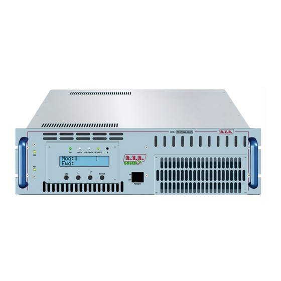
TEX1000LIGHT 4.3 Frontal Panel Description ELETTRONICA Figure 6.1 [1] ALARMS PS2 Not used. [2] ON Green LED - Turns on when exciter is powered on. [3] LOCK Green LED - Turns on when PLL is locked to operating frequency. [4] FOLDBACK Yellow LED - Turns on when foldback current limiting (Automatic Gain Control) kicks in. -
Page 12: Rear Panel Description
TEX1000LIGHT 4.4 Rear Panel Description Figure 6.2 [1] R.F. TEST Output with level -60 dB lower than output power level, suitable for modulation monitoring. Not suitable for spectrum analysis. [2] GSM SLOT-IN Reserved for future implementations. [3] GSM ANT Reserved for future implementations. -
Page 13: Connector Pinouts
TEX1000LIGHT [31] RS232 DB9 connector for direct serial communication or modem (only with telemetry option). [32] ADJ L Reserved for future implementations - adjustment trimmer for Left digital channel input. [33] ADJ R Reserved for future implementations - adjustment trimmer for Right digital channel input. - Page 14 TEX1000LIGHT 6.3.5 Remote Type: Female DB15 Pin Name Type Purpose Interlock Inhibits power if closed to Ext AGC FWD Ext. signal,1-12V, for limitation (AGC) Ground SDA IIC Serial data for IIC communication VPA Tlm ANL OUT PA supply voltage: 3.9V F.S.
-
Page 15: Quick Guide For Installation And Use
TEX1000LIGHT 5. Quick guide for installation and use This section provides a step-by-step description of equipment installation and configuration procedure. Follow these procedures closely upon first power-on and each time any change is made to general configuration, such as when a new transmission station is added or the equipment is replaced. -
Page 16: First Power-On And Setup
Connect the transmitter INTERLOCK IN input to the matching INTERLOCK OUT output fitted on R.V.R. Elettronica equipment to act as hybrid couplers. If your equipment is a different brand, identify an equivalent output. WARNING: Electric shock hazard! Never handle the RF output connector when the equipment is powered on and no load is connected. - Page 17 TEX1000LIGHT 5.2.1 Power-on When you have performed all of the connections described in the previous paragraph, power on the exciter using the suitable power switch on the front panel. 5.2.2 Power check Ensure that the ON LED turns on. Equipment name should appear briefly on the display, followed by forward power and modulation readings.
- Page 18 TEX1000LIGHT 5.2.5 Changing the Power Good alarm threshold Change Forward Power Good alarm setting PgD from the Fnc menu as desired (factory setting is 50%). Please read section 5.4.1 for more details. 5.2.6 Setting equipment I C address Change the IIC address in the MIX (Miscellaneous) menu as desired (factory setting is 01).
-
Page 19: Operation
TEX1000LIGHT • Preemphasis: 50 ms 75 ms • L and R (XLR type) input impedance: Switch 1: R XLR input impedance, ON = 600 W, OFF = 10 kW Switch 2: L XLR input impedance, ON = 600 W, OFF = 10 kW •... - Page 20 TEX1000LIGHT 25% output power 1/4 bar ≅ 250W in uscita (mod.TEX1000LIGHT) The bottom line provides instantaneous power reading (in this example 997W); press button to increase level, press to decrease it. When you have achieved the desired level, press ENTER to confirm and exit the default menu. Please note that the setting is stored automatically;...
-
Page 21: Management Firmware
TEX1000LIGHT 5.4 Management Firmware The machine features an LCD with two lines by 16 characters that displays a set of menus. Figure 5.2 below provides an overview of machine menus. The symbols listed below appear in the left portion of the display as appropriate: (Cursor) - Highlights selected (i.e. - Page 22 TEX1000LIGHT When the display is on, pressing the ESC button from the default menu (menu 1) calls up the selection screen (menu 3), which gives access to all other menus: Menu 3 If the temperature alarm is enabled and the alarm threshold is exceeded, the...
- Page 23 [7] of the DB15 “Remote” connector located on the rear panel. Modifies Power Good threshold for reflected power. The Power Good rate is a percent of equipment rated power (100 W for TEX1000LIGHT), not of reflected output power. This means that this threshold set at 10% will give 10W regardless of set power level.
- Page 24 TEX1000LIGHT 5.4.2 Power Menu (Pwr) This screen holds all readings related to equipment output power: Menù 5 Forward power reading. Reflected power reading. Note that these are readings, rather than settings, and cannot be edited (note the empty triangle). To change power setting, go to the default menu as outlined earlier.
- Page 25 TEX1000LIGHT Menu 7 Operating frequency setup. Set a new frequency value and then press the ENTER button to confirm your selection; the exciter unlocks from current frequency (the LOCK LED turns off) and will lock to the new operating frequency (LOCK turns back on again).
-
Page 26: Optional Functions
NOTE: This function is typically used in the USA. The factory setting for frequency shift amplitude is +10KHz and code repetition period is 60 minutes (please contact R.V.R. Elettronica if you need different settings), whereas station identified may be programmed by the user following the indications provided in section 5.5.1.1. - Page 27 A brief description of the procedure is provided below: • Connect the PC serial port COM to the SERVICE connector on the rear panel of TEX1000LIGHT using a standard Male DB9 - Female DB9 serial cable. • Power on the exciter;...
- Page 28 TEX1000LIGHT RF section on / off control signals are treated as control signals for RF output power level to allow for UP/DOWN setting. The UP or DOWN command is provided by switching the corresponding signal at the connector to ground for at least 500mS (pin features internal pull-up to power supply).
-
Page 29: Module Identification
TEX1000LIGHT 6. Module identification TEX1000LIGHT is made up of several modules connected through connectors to facilitate maintenance and replacement (if needed). 6.1 Top view The figure below shows a top view of the equipment and component locations. Figure 6.1 [1] BIAS board... -
Page 30: Bottom View
TEX1000LIGHT 6.2 Bottom view Figure 6.2 below shows a bottom view of the equipment and component locations. Figure 6.2 [1] FAN [2] Telemetry board [3] Surge Protection board [4] Service Power supply [5] Interface board / 30 User Manual Rev. 1.1 - 06/07/20... -
Page 31: Working Principles
TEX1000LIGHT 7. Working Principles The figures below provide an overview of TEX1000LIGHT (fig. 7.1) modules and connections. R.F. R.F. 2 X R.F. 2 X R.F. R.F. OUTPUT LPF + SPLITTER RF MODULES DRIVER COMBINER DIRECT. COUPL. VPA (46VDC) BIAS 2 X VPA (46VDC) R.F. -
Page 32: Interface Board
TEX1000LIGHT Inside the surge protection module, a suitable 24V relay controlled via the interface board. In this way, mains power supply is enabled when these requirements are met: • POWER switch on front panel set to ON; • No alarm or fault events present;... -
Page 33: Panel Board
TEX1000LIGHT 7.3 Panel board The panel board accommodates the microcontroller that runs equipment firmware and all user interface elements (display, LEDs, keys, …). This board is interfaced with other equipment modules via flat cables and provides for power supply, control signals and measurement distribution. -
Page 34: Power Amplifier
7.6 Power amplifier The RF power amplification section consists in several power modules (two on the TEX1000LIGHT) coupled through a Wilkinson splitter and combiner using strip-line technology. Each RF module provides its power share using a single active element built using LD-MOS technology. -
Page 35: External Telemetry Interface Board
TEX1000LIGHT Abnormal conditions affecting bias voltage so as to trigger foldback current limiting are: • Reflected output power too high • External AGC signals (Ext. AGC FWD, Ext. AGC RFL) • Temperature too high • Current draw of one RF module too high 7.9 External Telemetry Interface Board... - Page 36 TEX1000LIGHT This page was intentionally left blank / 30 User Manual Rev. 1.1 - 06/07/20...
- Page 37 ______________________________________________________________________________ ______________________________________________________________________________ ______________________________________________________________________________ ______________________________________________________________________________ ______________________________________________________________________________ ______________________________________________________________________________ ______________________________________________________________________________ ______________________________________________________________________________ ______________________________________________________________________________ ______________________________________________________________________________ ______________________________________________________________________________ ______________________________________________________________________________ ______________________________________________________________________________ ______________________________________________________________________________ ______________________________________________________________________________ ______________________________________________________________________________ ______________________________________________________________________________ ______________________________________________________________________________ ______________________________________________________________________________ ______________________________________________________________________________ ______________________________________________________________________________ ______________________________________________________________________________ ______________________________________________________________________________ ______________________________________________________________________________ ______________________________________________________________________________...
- Page 38 ______________________________________________________________________________ ______________________________________________________________________________ ______________________________________________________________________________ ______________________________________________________________________________ ______________________________________________________________________________ ______________________________________________________________________________ ______________________________________________________________________________ ______________________________________________________________________________ ______________________________________________________________________________ ______________________________________________________________________________ ______________________________________________________________________________ ______________________________________________________________________________ ______________________________________________________________________________ ______________________________________________________________________________ ______________________________________________________________________________ ______________________________________________________________________________ ______________________________________________________________________________ ______________________________________________________________________________ ______________________________________________________________________________ ______________________________________________________________________________ ______________________________________________________________________________ ______________________________________________________________________________ ______________________________________________________________________________ ______________________________________________________________________________ ______________________________________________________________________________...
- Page 39 ______________________________________________________________________________ ______________________________________________________________________________ ______________________________________________________________________________ ______________________________________________________________________________ ______________________________________________________________________________ ______________________________________________________________________________ ______________________________________________________________________________ ______________________________________________________________________________ ______________________________________________________________________________ ______________________________________________________________________________ ______________________________________________________________________________ ______________________________________________________________________________ ______________________________________________________________________________ ______________________________________________________________________________ ______________________________________________________________________________ ______________________________________________________________________________ ______________________________________________________________________________ ______________________________________________________________________________ ______________________________________________________________________________ ______________________________________________________________________________ ______________________________________________________________________________ ______________________________________________________________________________ ______________________________________________________________________________ ______________________________________________________________________________ ______________________________________________________________________________...
- Page 40 R.V.R Elettronica Via del Fonditore, 2 / 2c Zona Industriale Roveri · 40138 Bologna · Italy Phone: +39 051 6010506 · Fax: +39 051 6011104 e-mail: info@rvr.it ·web: http://www.rvr.it The RVR Logo, and others referenced RVR products and services are trademarks of RVR Elettronica in Italy, other countries or both. RVR ® 1998 all rights reserved. All other trademarks, trade names or logos used are property of their respective owners.
Need help?
Do you have a question about the TEX1000LIGHT and is the answer not in the manual?
Questions and answers