Table of Contents
Advertisement
Quick Links
Advertisement
Table of Contents

Subscribe to Our Youtube Channel
Related Manuals for R.V.R. Elettronica TEX52TFT


Summary of Contents for R.V.R. Elettronica TEX52TFT
- Page 1 TEX5 TEX52TFT 2TFT USER MANUAL VOLUME1 Manufactured by R.V.R. ELETTRONICA Italia...
- Page 2 Limitations of use can apply in respect of operating freuency, transmitter power and/or channel spacing. Declaration of Conformity Hereby, R.V.R. Elettronica, declares that this FM transmitter is in complian- ce with the essential requirements and other relevant provisions of Directive 2014/53/EU.
- Page 3 TEX52TFT ELETTRONICA Technical Specifications TEX52TFT Parameters U.M. Value Notes GENERALS Frequency range 87,5 - 108 Rated output power Continuously variable by software from 0 to maximum Modulation type F300E Operational Mode Mono, Stereo, MPX Working temperature °C -5 to 60...
- Page 4 TEX52TFT ELETTRONICA AUDIO INPUTS Connector XLR F Type Balanced Left / Mono Impedance 10 k or 600 Selectable by rear panel dip switches Input Level /Adjust -12 to +12 continuosly variable Connector XLR F Type Balanced Right Impedance 10 k or 600...
-
Page 5: Table Of Contents
TEX52TFT ELETTRONICA Table of Contents 1. Preliminary Instructions 2. Warranty 3. First aid 3.1 Treatment of electric shocks 3.2 Treatment of electrical burns 4. General description 4.1 Unpacking 4.2 Features 4.3 Description of the Front Panel 4.4 Description of the Rear Panel 4.5 Description of the Connectors... - Page 6 TEX52TFT ELETTRONICA Quick guide 1. Turn on the switch on the front panel 2. Set the working frequency via the FRQ menu To change the value, simply use the + or - buttons and then confirm with ENTER or cancel with ESC (in mechanical key mode) or type the value directly on the display (in touchscreen mode).
-
Page 7: Preliminary Instructions
The product should not be incorporated into a rack unless retailers. it is provided with adequate ventilation or the manufacturer's if your retailer cannot help you, contact R.V.R. Elettronica instructions have been followed. and describe the issue; if the staff deems it necessary, the authorization to send the equipment will be sent to you with the appropriate instructions;... -
Page 8: First Aid
TEX52TFT ELETTRONICA The customer always assumes the risks of loss (i.e., R.V.R. is never liable for damage or loss), until the package reaches the R.V.R. facility. For this reason, we suggest that you insure the goods for their full value. -
Page 9: General Description
- Minimum rated output power: 37 dBm ±1 dB - Gain : Not applicable (the equipment is supplied without a radiant system, which is the customer’s responsibility). The TEX52TFT is designed to be contained in a 2HE 19” rack box. 4.1 Unpacking The package contains the following: 1 TEX52TFT... -
Page 10: Features
(CCIR, FCC or ETSI) and can be connected directly to the antenna. The salient features of the TEX52TFT are compactness and great ease of use. Furthermore, the equipment is designed in a modular way: the various functions are performed by modules connected mostly with male and female connectors or with flat cables terminated by connectors. -
Page 11: Description Of The Front Panel
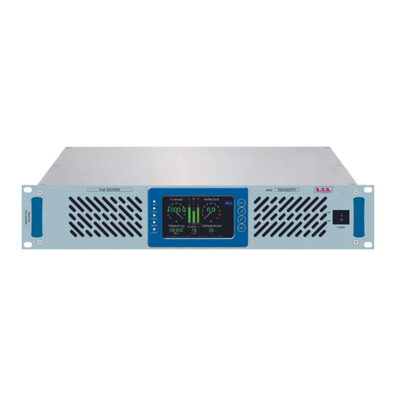
TEX52TFT ELETTRONICA 4.3 Description of the Front Panel F.M. EXCITER TEX1002TFT MOD. ELETTRONICA LOCK FOLD. MUTE POWER ENTER LOCAL Figure 4.1 [1] AIR FLOW Grids for forced ventilation. [2] ON Green LED, lit when the transmitter is power enabled. [3] LOCK Green LED, lit when the PLL is locked to the working frequency. -
Page 12: Description Of The Rear Panel
TEX52TFT ELETTRONICA 4.4 Description of the Rear Panel PHASE RIGHT R.F. OUTPUT MAINS VOLTAGE 50 Ω 24Vdc GSM/LAN EXT REF 10MHz 10KΩ 600Ω 10KΩ 600Ω SCA1/RDS CARRIER FREQ. ADJ EXT AGC R.F. TEST 19KHz PILOT SCA2 MAINS max 20dBm RFL FWD... -
Page 13: Description Of The Connectors
TEX52TFT ELETTRONICA 4.5 Description of the Connectors 4.5.1 Left (MONO) / Right Type: XLR female Positive Negative 4.5.2 Remote Type: DB15 female Pin Name Type Meaning Interlock Inhibits if power is closed to GND Ext AGC FWD External signal, 1-12V, for limitation (AGC) -
Page 14: Installation And Configuration Procedure
TEX52TFT ELETTRONICA 5. Installation and Configuration Procedure Instructions are given in this chapter on installation and configuration of the equipment. Carefully perform all the steps described in this chapter both upon initial start-up and every time the main configuration is changed, for example when moving to a new transmission station or when replacing the equipment. -
Page 15: Installation
TEX52TFT ELETTRONICA 5.1 Installation 5.1.1 General Requirements The ventilation of the equipment and workplace must be suitable for maintenance according to the directive in force in the country in which this equipment is installed. To ensure correct operation of the appliance, there must be a clearance of at least 50 cm at the front and back of the device to facilitate the circulation of air through the ventilation grids. - Page 16 TEX52TFT ELETTRONICA TEX52TFT @ 230 Vac Main fuse (1x) F 3.15AT type 5x20 Table 5.1: Fuses 5.1.2 Placement of the device Useful tips for correct installation: • Avoid the presence of external elements near the ventilation inlets and outlets, as they could prevent proper ventilation of the device.
- Page 17 TEX52TFT ELETTRONICA The station normally has an air outlet at the rear of the equipment: in which case, ensure adequate ventilation of the room. COLD 50cm Alternatively it is cooled by forced ventilation and the air intake is located on the roof of the equipment.
- Page 18 Note: to ensure the safety of the operators, prepare the wiring according to the laws and regulations in the country where this equipment is installed. Check that the POWER switch on the front panel of the TEX52TFT is in the “OFF” position.
- Page 19 √ For functional tests only: • a dummy load with 50 Ohm impedance and of appropriate power (minimum 50W for TEX52TFT-2GRL). • Coaxial cable with BNC connectors for connecting the interlock signal to the load protection. √ Connection cable kit including: •...
- Page 20 Check that the POWER switch on the front panel of the TEX52TFT is in the “OFF” position. Connect the audio and RDS/SCA cables of your sources to the input connectors.
- Page 21 TEX52TFT ELETTRONICA 5.1.5 Initial start-up and setting of operation For initial start-up, follow the procedure below. Note: RF EXPOSURE SAFETY DISTANCE (only for FCC & IC) RF Exposure Limits for the United States of America, according to FCC regulation: Set the output power of the unit to maximum to ensure the exposure limits stated in this document.
- Page 22 TEX52TFT ELETTRONICA Access the PWR menu and use the touchscreen or keys to adjust the output power of the equipment in steps of 1%; considering that the forward power value indicated on the display (Forward) provides the real reading of the output power.
-
Page 23: Management Firmware
TEX52TFT ELETTRONICA 5.2 Management Firmware The device has a TFT touchscreen display, on which a set of menus are shown which indicate all the operating parameters of the product. To navigate the menus, use the touchscreen or the four mechanical keys that operate in the same way. - Page 24 TEX52TFT ELETTRONICA Menu 1 NOTE: in power saving mode, the Menu key becomes ESC: press it to exit this mode. Pressing the ESC button (both in mechanical key and TouchScreen mode) while in the default menu (menu 1) opens the selection screen (menu 2), from which...
- Page 25 TEX52TFT ELETTRONICA 5.2.2 Power Menu (PWR) This screen shows the user the parameters relating to the power delivery of the device. To edit one of the items, select it with the + or - buttons (the selected item is highlighted) and then press the ENTER button (both in mechanical key and TouchScreen mode).
- Page 26 TEX52TFT ELETTRONICA 5.2.3 Frequency Menu (FRQ) This menu allows you to read and set the working frequency. To change the value, simply use the + or - buttons and then confirm with ENTER or cancel with ESC (in mechanical key mode) or type the value directly on the display (in touchscreen mode).
- Page 27 TEX52TFT ELETTRONICA At any time it is possible to return to the selection screen(menu 2) by pressing the ESC button (both in mechanical key and TouchScreen mode) or after one minute of inactivity. Menu 5 Mode Selection of the audio coder mode between mono, stereo or composite mode.
- Page 28 TEX52TFT ELETTRONICA 5.2.5 Amplifier Menu (PA) This menu allows you to read the parameters relating to the power amplifier. At any time it is possible to return to the selection screen (menu 2) by pressing the ESC button (both in mechanical key and TouchScreen mode) or after one minute of inactivity.
- Page 29 TEX52TFT ELETTRONICA 5.2.6 Real Time Clock (RTC) menu This menu allows you to read and set the time and date of the device. To modify the value, simply use the + or - buttons and then confirm with ENTER or cancel with ESC (in mechanical key mode) or type the value directly on the display (in touchscreen mode).
- Page 30 TEX52TFT ELETTRONICA 5.2.7 Frequency-shift keying (FSK) menu This menu provides the FSK (Frequency Shift Keying) adjustments of the exciter. To modify the value, simply use the + or - buttons and then confirm with ENTER or cancel with ESC (in mechanical key mode) or type the value directly on the display (in touchscreen mode).
- Page 31 The percentage value of Power Good refers to the nominal power of the device (50 W for the TEX52TFT), not to the direct power delivered. So if you set a value equal to 50%, it will correspond to 25 W, regardless of the power set.
- Page 32 TEX52TFT ELETTRONICA 5.2.9 Version menu (Vrs) This screen shows information about the version of the device. At any time it is possible to return to the selection screen (menu 2) by pressing the ESC button (both in mechanical key and TouchScreen mode) or after one minute of inactivity.
-
Page 33: Identification And Access To The Modules
ELETTRONICA 6. Identification and Access to the Modules 6.1 Identification of the Modules The TEX52TFT is composed of several modules which are interconnected with connectors to facilitate maintenance and replacement of the modules. 6.1.1 TEX52TFT Top view The figure below shows the top view of the device, indicating the various components. -
Page 34: Principles Of Operation
TEX52TFT ELETTRONICA 7. Principles of Operation There is a schematic view of the modules and connections that make up the TEX52TFT in figure 7.1. R.F. R.F. 1 X R.F. 1 X R.F. R.F. OUTPUT LPF + RF MODULES DIRECT. COUPL. -
Page 35: Telemetry Board
7.4 Power Supply Block The power supply of the TEX52TFT provides the two main power supplies: 1. Services. This voltage powers elements that do not directly affect the power supply such as the motherboard, panel board and fans. -
Page 36: Control Board
• Low-pass filter, which also includes the power meter. In this block there is an RF pickup at -46dB (for the TEX52TFT model) approximately with respect to the output which is available on a BNC connector below the transmitter output connector. This pickup is used to assess the characteristics of the carrier, but not those of the upper harmonics. -
Page 37: Maintenance And Repair Procedures
The fans should be replaced in case of problems as soon as possible and in any case at least every 24 months. 8.3.1 Replacing malfunctioning fans • Open the top cover of the TEX52TFT by unscrewing all the screws. • Disassemble the power supply module as described below. •... -
Page 38: Replacing The Modules
Arrange for authorized and qualified technical personnel to replace the component parts in the device. 8.4.1 Replacing the power supply Open the top cover of the TEX52TFT by unscrewing all the screws. • • Identify the power supply module to be replaced. - Page 39 TEX52TFT ELETTRONICA • Unscrew all points A using an Allen key. • Disconnect all connectors at points B. • Unscrew all points C using a flat head screwdriver. User Manual / 42 Rev. 1.0 - 12/07/20...
- Page 40 Put the cover back and tighten all the screws needed to close it. 8.4.2 Replacing the RF module • Open the top cover of the TEX52TFT by unscrewing all the screws. • Identify the RF module to be replaced. •...
- Page 41 TEX52TFT ELETTRONICA • Remove the RF module and replace it with the new module. • Repeat the procedure above in reverse order to reassemble and fix the module in its seat. • Put the cover back and tighten all the screws needed to close it.
- Page 42 TEX52TFT ELETTRONICA • Disconnect the connector C and unscrew the RF connector D. • Remove the motherboard and replace it with the new module. • Repeat the procedure above in reverse order to reassemble and fix the module in its seat.
- Page 43 TEX52TFT ELETTRONICA Remove panel C. • Unscrew all points D using a socket screwdriver, and then lift the protective • plastic cover. User Manual / 42 Rev. 1.0 - 12/07/20...
- Page 44 TEX52TFT ELETTRONICA • Disconnect the connectors E. Unscrew all points F internally using a screwdriver. • Disconnect the connector G, being very careful to unlock the two side locks • before proceeding with the operation. • Remove the panel lock and replace it with the new module.
-
Page 45: Options
TEX52TFT ELETTRONICA 9. Options This section shows views on the variants with respect to the basic version to be requested when ordering. For more information about the options, refer to the respective instruction manuals. 9.1 Option /AUDIGIN-TFT Digital Input Left (MONO) / Right... -
Page 46: Option \Tlw-Tft-E-2He
TEX52TFT ELETTRONICA Service/RDS Tipo: Femmina DB9 1 GND 2 RS232 TX 3 RS232 RX 4 NC 5 GND 6 NC 7 NC 8 RDS CARRIER OUT 9 PILOT IN 9.3 Option \TLW-TFT-E-2HE Ethernet Tipo: femmina RJ45 1 TX+ 2 TX-... -
Page 47: Option \Tlw-Tft-2He
TEX52TFT ELETTRONICA 9.4 Option \TLW-TFT-2HE RS232 Bus Modem Tipo: Femmina DB9 Tipo: Femmina DB9 1 NC 1 NC 2 TX_D 2 NC 3 RX_D 3 NC Internamente connesso con 6 5 GND 5 GND Internamente connesso +12 V con 4... -
Page 48: Up/Down Power Option (Software Only)
TEX52TFT ELETTRONICA 9.5 UP/DOWN Power option (software only) The UP/DOWN Power option modifies the function of receiving signals present on the telemetry connector. Specifically, the on and off control signals of the RF section become control signals of the emitted RF power level, allowing UP/DOWN adjustment. - Page 49 ______________________________________________________________________________ ______________________________________________________________________________ ______________________________________________________________________________ ______________________________________________________________________________ ______________________________________________________________________________ ______________________________________________________________________________ ______________________________________________________________________________ ______________________________________________________________________________ ______________________________________________________________________________ ______________________________________________________________________________ ______________________________________________________________________________ ______________________________________________________________________________ ______________________________________________________________________________ ______________________________________________________________________________ ______________________________________________________________________________ ______________________________________________________________________________ ______________________________________________________________________________ ______________________________________________________________________________ ______________________________________________________________________________ ______________________________________________________________________________ ______________________________________________________________________________ ______________________________________________________________________________ ______________________________________________________________________________ ______________________________________________________________________________ ______________________________________________________________________________...
- Page 50 ______________________________________________________________________________ ______________________________________________________________________________ ______________________________________________________________________________ ______________________________________________________________________________ ______________________________________________________________________________ ______________________________________________________________________________ ______________________________________________________________________________ ______________________________________________________________________________ ______________________________________________________________________________ ______________________________________________________________________________ ______________________________________________________________________________ ______________________________________________________________________________ ______________________________________________________________________________ ______________________________________________________________________________ ______________________________________________________________________________ ______________________________________________________________________________ ______________________________________________________________________________ ______________________________________________________________________________ ______________________________________________________________________________ ______________________________________________________________________________ ______________________________________________________________________________ ______________________________________________________________________________ ______________________________________________________________________________ ______________________________________________________________________________ ______________________________________________________________________________...
- Page 51 ______________________________________________________________________________ ______________________________________________________________________________ ______________________________________________________________________________ ______________________________________________________________________________ ______________________________________________________________________________ ______________________________________________________________________________ ______________________________________________________________________________ ______________________________________________________________________________ ______________________________________________________________________________ ______________________________________________________________________________ ______________________________________________________________________________ ______________________________________________________________________________ ______________________________________________________________________________ ______________________________________________________________________________ ______________________________________________________________________________ ______________________________________________________________________________ ______________________________________________________________________________ ______________________________________________________________________________ ______________________________________________________________________________ ______________________________________________________________________________ ______________________________________________________________________________ ______________________________________________________________________________ ______________________________________________________________________________ ______________________________________________________________________________ ______________________________________________________________________________...
- Page 52 R.V.R Elettronica Via del Fonditore, 2 / 2c Zona Industriale Roveri · 40138 Bologna · Italy Phone: +39 051 6010506 · Fax: +39 051 6011104 e-mail: info@rvr.it ·web: http://www.rvr.it The RVR Logo, and other RVR referenced products and services are trademarks of RVR Elettronica in Italy, other countries or both. RVR ® 1998 all rights reserved. All other trademarks, trade names or logos used are the property of their respective owners.
Need help?
Do you have a question about the TEX52TFT and is the answer not in the manual?
Questions and answers