Advertisement
Quick Links
ASSEMBLY INSTRUCTIONS
ITEM: 2459 / 2459(3A)
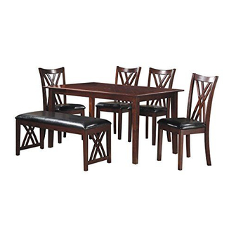
6pcs Pack Dinette / Espresso
This page lists all the contents included in the box. Please take the time to identify
the hardware as well as the individual components to this product. As you unpack
and prepare for assembly, place the contents on a carpeted or padded area to
protect them from damage.
c l e a n i n g & c a r e
Treat surface with care. Clean surfaces with a dry or
damp soft cloth. Do not use abrasive cleaners. Hardware may loosen over time.
Periodically check that all connections are tight.
A Phillips head screwdriver is necessary for assembly.
1
Advertisement

Summary of Contents for Homelegance 2459
- Page 1 ASSEMBLY INSTRUCTIONS ITEM: 2459 / 2459(3A) 6pcs Pack Dinette / Espresso This page lists all the contents included in the box. Please take the time to identify the hardware as well as the individual components to this product. As you unpack and prepare for assembly, place the contents on a carpeted or padded area to protect them from damage.
- Page 2 TABLE PART LIST A. TABLE TOP 1 PC B. TABLE LEG 4 PCS...
- Page 3 TABLE ASSEMBLY INSTRUCTIONS DIAGRAM #1 1. Place table top (A) upside down REQUIRED HARDWARE IN THIS STEP on a non-abrasive surface such DESCRIPTION SKETCH as carpet (underside of tabletop 8 PCS FLAT WASHER should be facing up). 8 PCS SPRING WASHER 8 PCS 2.
- Page 4 CHAIR PART LIST C. CHAIR BACK 4 PCS D. SEAT FRAME 4 PCS E. FRONT LEG 8 PCS F. CUSHION 4 PCS...
- Page 5 CHAIR ASSEMBLY INSTRUCTIONS DIAGRAM #3 REQUIRED HARDWARE IN THIS STEP DESCRIPTION SKETCH FLAT WASHER 4 PCS SPRING WASHER 4 PCS PLASTIC PLUG 4 PCS 1 PC OPEN WRENCH 1. Attach 2 front legs (E) to seat frame (D) using 4 nuts (3), 4 spring washers (2), and 4 flat washers (1) as shown.
- Page 6 CHAIR ASSEMBLY INSTRUCTIONS DIAGRAM #5 REQUIRED HARDWARE IN THIS STEP DESCRIPTION SKETCH WOOD SCREW 6 PCS 4. Place cushion seat (F) upside down on a non-abrasive table surface. The rear ( tapered end ) of the cushion seat (F) should be near the table edge. Hint: Protect the non-abrasive table surface and cushion seat (F) by laying a towel in-between the chair seat and table.
- Page 7 BENCH PART LIST G. CUSHION 1 PC H. SEAT FRAME 1 PC I. LEFT FRONT/RIGHT BACK LEG 2 PCS J. RIGHT FRONT/LEFT BACK LEG 2 PCS K. SIDE PANEL 2 PCS L. SIDE CROSSBAR 2 PCS...
- Page 8 BENCH ASSEMBLY INSTRUCTIONS DIAGRAM #7 1. Attach 2 side panels (K) to seat frame (H) and side crossbars (L) as shown. Note: The seat frame (I) has 4 holes on each long side, which are used to attach the seat cushion.
- Page 9 BENCH ASSEMBLY INSTRUCTIONS DIAGRAM #9 REQUIRED HARDWARE IN THIS STEP DESCRIPTION SKETCH WOOD SCREW 8 PCS 3. Place cushion seat (G) upside down on a non-abrasive surface. Hint: Protect the non-abrasive table surface and cushion seat (F) by laying a towel in-between the chair seat and table.


Need help?
Do you have a question about the 2459 and is the answer not in the manual?
Questions and answers