Table of Contents
Advertisement
Quick Links
Advertisement
Table of Contents

Related Manuals for Godiva World Series


Summary of Contents for Godiva World Series
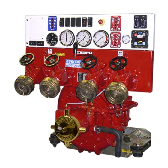
- Page 1 World Series Pump with Integrated SmartCAFS 200 Installation and Operation Manual GODIVA LTD A Unit of IDEX Corporation Charles St Warwick CV34 5LR England +44 (0)1926 623600 +44 (0)1926 623666 www.godiva.co.uk GP/252 godiva@idexcorp.com Issue 3, April 2012...
-
Page 2: Amendment Record
AMENDMENT RECORD Model: SmartCAFS200 Manual Date Page/s Amendment New Issue July 2006 New Issue Issue 1, September New diagram/photograph for air injection point Issue 2 2008 April 2012 Gearbox oil capacity – now 1.2 litres Issue 3 ©Hale Products Europe. Our policy is one of continuous development. We therefore reserve the right to amend specifications without notice or obligation. -
Page 3: Table Of Contents
AMENDMENT RECORD .................... 2 INTRODUCTION ......................5 IMPORTANT NOTES ....................5 SAFETY - RELEVANT DATA ..................6 ......................6 AINTENANCE ........................6 RAINING ......................6 AFETY OINTS ........................6 OISE ENVIRONMENTAL PROTECTION ................7 GENERAL DATA ....................... 8 ......................8 OMPRESSOR ..................... - Page 4 ..............23 OGIX ONTROL ANEL UNCTIONS ..............23 OMMISSIONING TART ROCEDURE ................... 24 ALIBRATION OF OGIX WT_C WS_C ......27 PERATING THE FROM A EHICLE ATER OURCE .................. 27 OGIX ONTROL ANEL PTO & P ..............27 NGAGING RIMING ................28 ISCHARGING GENT CAFS ....................
-
Page 5: Introduction
INTRODUCTION This manual contains information relevant to Godiva single or multi-pressure World Series Pumps, when partnered with Compressed Air Foam Systems (CAFS) FoamLogix Models 3.3, 5.0 & 6.5. Other than performance, foam capability and installation of the FoamLogix units, the Godiva components are common. -
Page 6: Safety - Relevant Data
SAFETY - RELEVANT DATA Thank you for purchasing a Godiva Pump. Godiva Pumps are designed to give safe and reliable service. BEFORE use however, it is essential that the Operating and Installation Instructions are carefully read and understood. Maintenance It is the responsibility of the user to ensure that the equipment is maintained in a safe operational condition. -
Page 7: Environmental Protection
ENVIRONMENTAL PROTECTION It is prohibited to pour engine oil and other contaminants onto the ground, down sewers, drains, or into water courses. Dispose of lubricants through authorised waste disposal contractors, licensed waste disposal sites, or to the waste reclamation trade. If in doubt, contact your Local Environmental Agency for advice regarding disposal policies. -
Page 8: General Data
GENERAL DATA Compressor Model Enduro 12 Maximum Operating Speed 6500 rev / min Nominal speed of operation 5000 rev / min Nominal power consumption 40.0kW Direction of rotation Anti-clockwise (viewed on pulley) Cooling System Type Oil / Water Shell & tube type Cooling water flow-rate 50 Litres / Min at 7.0 Bar Foam Proportioning System 3.3, 5.0, 6.5 - Class A and B Foam Compatible... -
Page 9: Lubricants
(Capacity 0.75 litres approximately). Recommended: 10W/40 or 15W/40 Multi- grade engine oil. Model Identification System Variations of the World Series pump with CAFS are identified thus: W T A C Compressed air foam A = aluminium B = bronze T = twin pressure: S = single pressure World Series Pump ©Hale Products Europe. -
Page 10: Recommended Foam Agents
RECOMMENDED FOAM AGENTS Hale FoamLogix Models 2.1A and 3.3 approved Foam compatibility list. Type of Foam Concentrate Manufacturer Brand Name CLASS A FOAM US Forestry ANSUL Silvex Class A Foam Concentrate Service Angus Forexpan S (0.1%-1.0%) Approved 1st Defense Class A Cold water Chubb National Foam Foam Chubb National Foam... -
Page 11: Foamlogix 3.3/5.0 Component Group
FoamLogix 3.3/5.0 Component Group FoamLogix Pump Literature Dual Tank Pack Selector Vehicle Interface Harness Dual Tank Extension Harness Dual Tank Instruction Plate Link Harness In-Line Filter / Valve Assembly ©Hale Products Europe. Our policy is one of continuous development. We therefore reserve the right to amend specifications without notice or obligation. -
Page 12: System Overview
SYSTEM OVERVIEW The WT_C or WS_C is a Compressed Air Foam System comprising of five major components – Air compressor, FoamLogix (foam proportioning unit) CAFS Manifold (foam mixing and control system), Oil-water heat exchanger & Separator tank A metered amount of foam is introduced into the Manifold and mixed with water from the pump discharge manifold. -
Page 13: Manifold
Manifold The manifold incorporates an air ratio control valve through which degrees of wet or dry foam mixture can be selected. Compressed air is then injected and the resulting foam / water / air combination is thoroughly mixed by the X-mixers during discharge. A By-pass valve is fitted to help obtain the required dry foam flow rate, this valve is adjusted and set during the installation stage, it is not required during normal operation. -
Page 14: Oil Filling Points
Oil Filling Points The unit is supplied without oil and must be filled with the correct quantity and specification before starting the pump. Bearing Housing Bearing housing oil filling point For oil type and capacity refer to Recommended Gearbox The pump gearbox filling point depends on the gearbox position in relation to the pump. -
Page 15: Gearbox In Horizontal Position, Left Or Right Of Pump
Gearbox in Horizontal Position, Left or Right of pump The oil filling point is on the side of the casing (RH gearbox shown) and is symmetrically opposite for LH gearbox. The oil level check point is lower on the side. Oil capacity and type as down position detail. -
Page 16: Separator Tank/Compressor
Separator Tank/Compressor Oil level indicator Oil Fill Point Note. Separator must be installed in the vertical position as shown. Pipework from compressor to oil tank must be arranged so that any oil in the compressor will drain back to the tank. ©Hale Products Europe. -
Page 17: Compressor Drive Belt
Compressor Drive Belt The compressor is driven by a synchronous belt. The installer must allow for access to adjust the jockey pulley belt tensioner. Tension the belt to achieve a 6-8mm deflection with a 6kg load applied at mid span, see diagram below. -
Page 18: Foam Tank Low Level Sensor
Foam Tank Low Level Sensor The unit is supplied with a connector for a low foam level sensor. The sensor is supplied with the unit ready for installation (instructions supplied with the sensor). Note: the low foam level switch must be installed in the tank in the correct orientation. - Page 19 Plumbing Layout ©Hale Products Europe. Our policy is one of continuous development. We therefore reserve the right to amend specifications without notice or obligation.
-
Page 20: By-Pass Valve
Note hoses marked * should be capable of withstanding pressures of 10 bars and temperatures of 110 CAFS Manifold By-pass valve lever for setting dry foam consistency Foam Injection Water flow 3” Victaulic connection Air Injection (Both ends) Manifold should be mounted with provision for drainage. Foam and air injection points identified above. -
Page 21: Electrical Wiring Connections
ELECTRICAL WIRING CONNECTIONS The electrical wiring connections are as follows: Connection Purpose Comments Air Enable light Vehicle builder supply Overheat warning light Vehicle builder supply CAFS enable switch Vehicle builder supply Smart Switch Connect to Smart Switch Power supply Fuse Fuse CAN Connection CAN Connection... -
Page 22: Vehicle Design Considerations
VEHICLE DESIGN CONSIDERATIONS The following information is included to assist the vehicle builder to achieve a successful installation. The in-line foam strainer / valve assembly is a low-pressure device, rated at 3 bar and will NOT withstand high flushing water pressure. Seal all electrical power and ground connections with silicone sealant to prevent corrosion. -
Page 23: Installation And Initial Set-Up Foamlogix
INSTALLATION AND INITIAL SET-UP FOAMLOGIX. Installation of the WT_C or WS_C assembly into a vehicle, when sourced with a FoamLogix 3.3 system is the same as the integrated 2.1A option, with the exception of the remote mounted foam pump assembly. For pump installation, please refer to the FoamLogix Model 3.3 &... -
Page 24: Calibration Of Foamlogix
Turn the bypass valve on the FoamLogix to bypass and provide a suitable receptacle to collect the foam, agent. Ensure that there is sufficient foam agent in the tank(s). For two tank systems, select tank A Select simulated flow on the FoamLogix by pressing both up ↑ & down ↓ at the same time. - Page 25 Smart Switch operation The CAFSAttack SPS Panel is the primary component of the CAFSAttack with compressor air-inject system. The SPS Panel allows monitoring and control of the consistency of the discharged CAFS concentrate. WET and DRY buttons The WET (or DRY) button is used to position the water valve at the preset position for the desired CAFS consistency.
- Page 26 Configure the WET and DRY presets The operator can set the WET and DRY presets for desired CAFS consistency. Configure the WET preset Press and hold the WET and DRY buttons simultaneously until the WET and DRY LEDs and backlighting begin flashing (approximately three seconds). Release the buttons.
-
Page 27: Operating The Wt_C Ws_C From A Vehicle Water Source
Operating the WT_C WS_C from a Vehicle Water Source 1. Connect a suitable delivery hose and branch to the CAFS discharge. φ38 to φ45mm diameter lay flat hose with a φ25 to φ38mm smooth bore nozzle is suitable for delivering compressed air foam. Note: Superior foam quality is produced using a smooth bore nozzle and a delivery system with the least amount of valves and sharp bends. -
Page 28: Discharging Foam Agent Only
Discharging Foam Agent Only (May be operated from open water, tank, or hydrant into pump suction) 1. Set pump at required pressure. 2. Ensure that the compressor clutch is not engaged. 3. Press the on button, and choose desired foam % setting to suit the foam agent being used and the operating conditions (factory default is 0.5% for Class A foam and 3% for Class B foam, if configured to run with two foam Foam to water ratio (%) -
Page 29: Shutting Down
Shutting Down 1. Turn off compressor. 2. Turn off the FoamLogix, press RED button. 3. Set pump to fast idle. 4. Run water through the CAFS discharge system to flush out the foam agent. 5. Close the CAFS discharge valves. 6. -
Page 30: Maintenance Schedule Wt(S)_C
Note: Both the drive belt and the air cleaner may have to be renewed more often in dusty, dirty or heavy duty applications. Note: The Godiva Compressor service intervals replace those in the Gardner Denver Compressor manuals MAINTENANCE SCHEDULE FOAMLOGIX... -
Page 31: Maintenance Operations Compressor
MAINTENANCE OPERATIONS COMPRESSOR Compressor Oil Level Check - Oil / Filter Change Please refer to section Installation and Initial Set-Up for location of level checking, drain and filling features. Drain oil and change the filter (with the compressor warm) in accordance with the instructions in the Gardener Denver Tamrotor Tempest manual. -
Page 32: Fault Finding
FAULT FINDING EFFECT CAUSE ACTION Compressor No water supply or restricted Check oil cooler pipe work overheats flow for obstructions Unable to produce FoamLogix not operating Switch on FoamLogix foam solution No Foam in tank Refill with foam agent FoamLogix not Primed Prime FoamLogix No air injection Compressor not selected...
Need help?
Do you have a question about the World Series and is the answer not in the manual?
Questions and answers