Sign In
Upload
Download
Table of Contents
Contents
Add to my manuals
Delete from my manuals
Share
URL of this page:
HTML Link:
Bookmark this page
Add
Manual will be automatically added to "My Manuals"
Print this page
×
Bookmark added
×
Added to my manuals
Manuals
Brands
Godiva Manuals
Water Pump
Prima P1
Installation and operation manual
Godiva Prima P1 Installation And Operation Manual
Single pressure; twin pressure
Hide thumbs
1
2
Table Of Contents
3
4
5
6
7
8
9
10
11
12
13
14
15
16
17
18
19
20
21
22
23
24
25
26
27
28
29
30
31
32
33
34
35
36
page
of
36
Go
/
36
Contents
Table of Contents
Bookmarks
Table of Contents
Amendment Record
Table of Contents
Contents
Safety
In Operation
Training
Maintenance
Environmental Protection
Risk Assessment
Transportation and Storage
Post-Production Cleaning Fluid
Warranty
Associated Publications
Pump Specification Numbering
Technical Data
Features Unique to P1 or P2 Model Only Are Indicated, Other Parts Are Common
Description
En Designation (en 1028:-1:2002)
Essential Installation Data
Installation
Commissioning
Operation
Basic Operation
Operator Controls
Operation - from an Open Water Source, Piston Priming
Automatic Priming (if Installed by OEM)
Manual Priming (if Installed by the OEM)
Operation - from a Pressurised Source, E.g. Hydrant or Vehicle Tank
P2 - High Pressure Operation
Collecting Head Use
Shutdown
Maintenance
Vacuum Test
Pressure Test - Carried out Without Pump Running
P2 - Thermal Relief Valve (Trv) Test
Gauges (if Fitted)
Fault Finding
Operator Maintenance Log
Advertisement
Quick Links
1
In Operation
2
Description
3
Technical Data
4
Basic Operation
5
Operation - from an Open Water Source, Piston Priming
6
Automatic Priming (if Installed by Oem)
7
Vacuum Test
Download this manual
Godiva Ltd
A Unit of IDEX Corporation
Charles St
Warwick CV34 5LR
England
Tel +44 (0)1926 623600
Fax +44 (0)1926 623666
www.godiva.co.uk
godiva@idexcorp.com
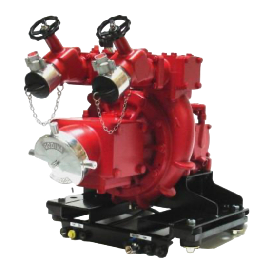
P1 Single Pressure
P2 Twin Pressure
Installation and
Operation Manual
Prima P1
Prima
Prima P2
GP/287
Issue 5 June 2016
Table of
Contents
Previous
Page
Next
Page
1
2
3
4
5
Advertisement
Table of Contents
Need help?
Do you have a question about the Prima P1 and is the answer not in the manual?
Ask a question
Questions and answers
Related Manuals for Godiva Prima P1
Water Pump Godiva Prima P2 Installation And Operation Manual
Single pressure; twin pressure (36 pages)
Water Pump Godiva Prima PC1 Installation And Operation Manual
With smartcafs50 or smartcafs100 control with foamlogix 2.1a, 3.3 or 5.0 systems (61 pages)
Water Pump Godiva WTA2010 Maintenance Instructions And Workshop Manual
World series; wt series multi-pressure pump (39 pages)
Water Pump Godiva PowerFlow 17/10 Workshop Manual
Portable fire pump (424 pages)
Water Pump Godiva World Series Installation And Operation Manual
Pump with integrated smartcafs 200 (32 pages)
Water Pump Godiva WT C Series Installation & Operation Manual
Series pump with integrated cafs (48 pages)
This manual is also suitable for:
Prima p2
Table of Contents
Save PDF
Print
Rename the bookmark
Delete bookmark?
Delete from my manuals?
Login
Sign In
OR
Sign in with Facebook
Sign in with Google
Upload manual
Upload from disk
Upload from URL


Need help?
Do you have a question about the Prima P1 and is the answer not in the manual?
Questions and answers