Table of Contents
Advertisement
Specifications*
General
Power Supply
DC 12V (10.5V - 16V),
Test Voltage 13.2V
Negative Ground
Current Consumption
3A or less (0.5W output)
Power Output
17.5W×4
Dark Current
0.3mA or less
AM Radio
Frequency Range
LW: 153 - 279kHz
MW: 522 - 1,611kHz
Usable Sensitivity
LW: 40dB(µV) or less
MW: 34dB(µV) or less
Signal to Noise Ratio
LW: 22dB or more
MW: 21dB or more (35dB(µV))
MW: 42dB or more (74dB(µV))
CQ-TS6670LC
CQ-TS6671LC
AM/FM/RDS
MPX
TUNING Radio with CD Player
TOYOTA PART No. : 86120-05110(CQ-TS6670LC)
86120-05120(CQ-TS6671LC)
ID CODE
: W58830 (CQ-TS6670LC)
W58831 (CQ-TS6671LC)
VEHICLE
: AVENSIS
DESTINATION
: Europe
PRODUCED AFTER : Mar., 2006
NOTE: CQ-TS6670LC is black while CQ-TS6671LC is
silver.
FM Stereo Radio
Frequency Range
87.5 - 108MHz
Usable Sensitivity
14dB(µV) or less (S/N 30dB)
Signal to Noise Ratio
35dB or more (18dB(µV))
46dB or more (54dB(µV))
RDS Radio
RDS Sensitivity
22dB(µV)
CD Player (YGFD15314)
Channel Separation
60dB or more (1kHz BPF)
Signal to Noise Ratio
65dB or more (IHF-A)
Dimensions**
178×100×151.4mm (W×H×D)
Weight**
2060g
* Specifications and the design are subject to possible
modification without notice due to improvements.
** Dimensions and Weight shown are approximate.
ELECTRONIC
Advertisement
Table of Contents

Related Manuals for Toyota CQ-TS6670LC


Summary of Contents for Toyota CQ-TS6670LC
- Page 1 ID CODE : W58830 (CQ-TS6670LC) W58831 (CQ-TS6671LC) VEHICLE : AVENSIS DESTINATION : Europe PRODUCED AFTER : Mar., 2006 NOTE: CQ-TS6670LC is black while CQ-TS6671LC is silver. Specifications* General FM Stereo Radio Power Supply DC 12V (10.5V - 16V), Frequency Range 87.5 - 108MHz...
-
Page 2: Table Of Contents
CQ-TS6670LC / CQ-TS6671LC CONTENTS Page Page 1 FEATURES 7 PACKAGE AND IC BLOCK DIAGRAM 2 SYSTEM BLOCK DIAGRAM (For Testing) 8 REPLACEMENT PARTS LIST 3 VIEWS AND FUNCTIONS 9 EXPLODED VIEW (Unit) 4 WIRING CONNECTION 10 WIRING DIAGRAM 5 BLOCK DIAGRAM... -
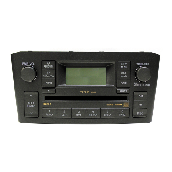
Page 3: Views And Functions
CQ-TS6670LC / CQ-TS6671LC 3 VIEWS AND FUNCTIONS... -
Page 4: Wiring Connection
CQ-TS6670LC / CQ-TS6671LC 4 WIRING CONNECTION... -
Page 5: Block Diagram
CQ-TS6670LC / CQ-TS6671LC 5 BLOCK DIAGRAM 5.1. Main / Display Block... -
Page 6: Terminals Description
CQ-TS6670LC / CQ-TS6671LC 6 TERMINALS DESCRIPTION 6.1. Main Block LCD-DET H: Normal L: S1D15605 sudden 4.5 4.5 4.5 drop LCD- H: Normal L: LCD reset O 4.5 4.5 4.5 IC600: C2DBLK000110 RESET No. Port Descriptions I/O FM AM CD LCD-CS2 S1D15605 chip select terminal 2 O 4.5 4.5 4.5... - Page 7 CQ-TS6670LC / CQ-TS6671LC VOL-A VOL encoder input terminal A 3.1 3.1 3.2 VOL-B VOL encoder input terminal B 3.1 3.1 3.2 A-DIM H: TAIL cancel off notice (ADIM OFF) L: TAIL cancel off notice (ADIM ON) LCD- Thermistor input 2.6 2.6 2.6...
-
Page 8: Package And Ic Block Diagram
CQ-TS6670LC / CQ-TS6671LC 7 PACKAGE AND IC BLOCK DIAGRAM 7.1. Main Block IC400: C2HBCH000008 IC702: C0CBABG00027 IC401: C0DBEJG00001... - Page 9 CQ-TS6670LC / CQ-TS6671LC IC701: C1EB00000110...
- Page 10 CQ-TS6670LC / CQ-TS6671LC IC870: C1EB00000017 IC231: C1BA00000345 IC871: C1BB00000844 PA51: J3CCAZ000005...
-
Page 11: Replacement Parts List
Panasonic Automotive Systems Europe GmbH (PASE). CAPACITORs 6. “A“ or “B“ marks in remarks column are indicated as follows: YECUZ1H221JC Ceramic, 220PF 50WV • • • • A: CQ-TS6670LC YECUZ1H102KX Ceramic, 1000PF 50WV F1H1H100A226 Ceramic, 10PF 50WV • • • • B: CQ-TS6671LC... - Page 12 CQ-TS6670LC / CQ-TS6671LC Ref. Part No. Part Name & Description Remarks Ref. Part No. Part Name & Description Remarks C325 F1J1E2240009 Ceramic, 0.22µF 25WV C703 F1J1C1050013 Ceramic, 1µF 16WV C326 F1J1E2240009 Ceramic, 0.22µF 25WV C704 F1J1C1050013 Ceramic, 1µF 16WV C327 F1J1E2240009 Ceramic, 0.22µF 25WV...
- Page 13 CQ-TS6670LC / CQ-TS6671LC Ref. Part No. Part Name & Description Remarks Ref. Part No. Part Name & Description Remarks Chip, 1Ω Ω Ω Ω 1/16W Chip, 1kΩ Ω Ω Ω 1/16W ERJ3GEYJ1R0V R434 ERJ3GEYJ102V Chip, 0Ω Ω Ω Ω 1/8W Chip, 0Ω...
- Page 14 CQ-TS6670LC / CQ-TS6671LC Ref. Part No. Part Name & Description Remarks Ref. Part No. Part Name & Description Remarks Chip, 0.47Ω Ω Ω Ω 1/10W R710 ERJ6GEYJR47V Chip, 0.47Ω Ω Ω Ω 1/10W R711 ERJ6GEYJR47V Chip, 100kΩ Ω Ω Ω 1/16W...
- Page 15 CQ-TS6670LC / CQ-TS6671LC Ref. Part No. Part Name & Description Remarks Ref. Part No. Part Name & Description Remarks Chip, 100Ω Ω Ω Ω 1/10W D917 B3ACB0000067 Diode R971 ERJ6GEYJ101 Chip, 0Ω Ω Ω Ω 1/16W D918 B3ACB0000067 Diode R972 ERJ3GEY0R00V Chip, 0Ω...
-
Page 16: Exploded View (Unit)
CQ-TS6670LC / CQ-TS6671LC 9 EXPLODED VIEW (Unit) -
Page 17: Wiring Diagram
CQ-TS6670LC / CQ-TS6671LC 10 WIRING DIAGRAM 10.1. Main Block (Top View) - Page 18 CQ-TS6670LC / CQ-TS6671LC 10.2. Main Block (Bottom View)
- Page 19 CQ-TS6670LC / CQ-TS6671LC 10.3. Display Block (Top View)
- Page 20 CQ-TS6670LC / CQ-TS6671LC 10.4. Display Block (Bottom View)
-
Page 21: Schematic Diagram
CQ-TS6670LC / CQ-TS6671LC 11 SCHEMATIC DIAGRAM 11.1. Main Block... - Page 22 CQ-TS6670LC / CQ-TS6671LC 11.2. Display Block...
-
Page 23: Memo
CQ-TS6670LC / CQ-TS6671LC 12 MEMO... - Page 24 CQ-TS6670LC / CQ-TS6671LC...
- Page 26 CONTENTS Page Page 1 FEATURES 6 IC BLOCK DIAGRAM (CD Deck) 2 LASER PRODUCTS 7 REPLACEMENT PARTS LIST 3 WIRING CONNECTION (CD Deck) 8 EXPLODED VIEW (CD Deck) 4 BLOCK DIAGRAM (CD Deck) 9 WIRING DIAGRAM (CD Servo) 5 TERMINALS DESCRIPTION (CD Deck) 10 SCHEMATIC DIAGRAM (CD Servo) 1 FEATURES 2 LASER PRODUCTS...
-
Page 27: Block Diagram (Cd Deck)
4 BLOCK DIAGRAM (CD Deck) -
Page 28: Terminals Description (Cd Deck)
5 TERMINALS DESCRIPTION (CD Deck) IC301 : MNBC77CWPUC Port Description Port Description 54 NC No Connection 55 NC No Connection Mechanics SW clamping (H: Non- 56 PHOTO Photo sensor actuating signal completion L: Completion) 57 NC No Connection Mechanics SW inner (H:OFF L: 58 NC No Connection Surroundings ON) -
Page 29: Ic Block Diagram (Cd Deck)
6 IC BLOCK DIAGRAM (CD Deck) IC101 MNG7945ECUC IC302 C3EBDG000058 IC901 AN41015A-VF IC905 C0JBAE000333... -
Page 30: Replacement Parts List
7 REPLACEMENT PARTS Ref. Part No. Part Name & Description Remarks LIST C130 F1H1H102A831 Ceramic, 1000PF 50WV C131 YECUZ1C104KX Ceramic, 0.1µF 16WV C132 F1H0J1050010 Ceramic, 1µF 6.3WV Notes : C136 F1H0J1050010 Ceramic, 1µF 6.3WV C139 YECUZ1C104KX Ceramic, 0.1µF 16WV 1. Be sure to make your orders of replacement parts C140 F1H1H103A221 Ceramic, 0.01µF 50WV... - Page 31 Ref. Part No. Part Name & Description Remarks Ref. Part No. Part Name & Description Remarks Chip, 120Ω Ω Ω Ω 1/16W R509 ERJ3GEYJ121V YGP0FX5754 Suspention Unit Chip, 120Ω Ω Ω Ω 1/16W R510 ERJ3GEYJ121V Chassis Chip, 120Ω Ω Ω Ω 1/16W R513 ERJ3GEYJ121V Detect Lever...
-
Page 32: Exploded View (Cd Deck)
8 EXPLODED VIEW (CD Deck) -
Page 33: Wiring Diagram (Cd Servo)
9 WIRING DIAGRAM (CD Servo) 9.1. CD Servo Block (Top View) - Page 34 9.2. CD Servo Block (Bottom View)
-
Page 35: Schematic Diagram (Cd Servo)
10 SCHEMATIC DIAGRAM (CD Servo)
Need help?
Do you have a question about the CQ-TS6670LC and is the answer not in the manual?
Questions and answers