Table of Contents
Advertisement
Advertisement
Table of Contents

Subscribe to Our Youtube Channel
Related Manuals for Risco WICOMM RW232M

Summary of Contents for Risco WICOMM RW232M
- Page 1 WICOMM Smart Hub Reference Manual Models: RW232M, RW232M8B, RW232M8C, RW232M87...
-
Page 2: Table Of Contents
................... NSTALLATION SYSTEM COMPONENTS ............5 ................IT AND PTIONAL EVICES ....................ERIAL UMBERS GUIDELINES FOR USING THE RISCO EXPRESS INSTALLATION WIZARD .............. 9 ................... NSTALLATION .................... ELCOME CREEN ..................ONNECT TO ETWORK Co e ti g a et ork a le to the WiCo S art Hu ......... - Page 3 A ti ati g the attery ..................9 ..........OW TO OUNT THE INDOW ETECTOR Mou ti g ith Adhesi e Tape ................ 9 Mou ti g ith S re s ..................PIR D ..........CTIVATING THE ATTERIES OF THE ETECTOR PIR D ..............
-
Page 4: Introduction
Note: It is recommended to add additional devices before starting the self-installation process. Self-Installation For basic and simple installation it is necessary to use the RISCO Express Wizard that explains step-by-step on how to program and install the system (see 3. GUIDELINES FOR USING THE RISCO EXPRESS WIZARD). -
Page 5: System Components
System Components Kit and Optional Devices The following list includes the full range of components and devices available for the Smart Hub. Some of these components and devices are included inside the kit you purchased and others can be purchased separately. Note: The type and quantity of components and devices inside the kit may vary from kit to kit. - Page 6 Wireless Slim Keypad including proximity reader for using proximity tags 4 Button Remote Keyfob Magnetic Door/Window Contact (includes detector and magnet) A “pet-friendly” PIR Motion Detector A “pet-friendly” PIR Motion Detector with Camera Wireless Smoke and Heat Detector WiComm Reference Manual...
- Page 7 Indoor Wireless Sounder Wireless acoustic Glassbreak Detector Wireless Flood Detector Note: For device Technical Specifications, see RISCO’s website at https://www.riscogroup.com. WiComm Reference Manual...
-
Page 8: Serial Numbers
Serial Numbers Serial numbers are used to identify the components of your security system as used in the RISCO Express Wizard. Each serial number consists of 11 digits. It is recommended to keep a record of component serial numbers and locations that correspond to the devices serial numbers, as shown in these illustrations. -
Page 9: Guidelines For Using The Risco Express Installation Wizard
Guidelines for using the RISCO Express Installation Wizard Self-Installation It is necessary to use the RISCO Express Wizard to successfully and professionally install your WiComm Smart Hub System. The RISCO Express Wizard walks you through the programming and installation of the system and connecting to the Cloud and Monitoring Station. -
Page 10: Personal Info
Please note that it may take a few minutes until communication with the cloud is established, before continuing with the RISCO Express Installation Wizard setup. 3. Continue with the remainder of the installation wizard and test the system until all the devices are successfully installed, as indicated in the wizard. -
Page 11: System Info
Next, enter the 4-digit verification code sent to your inbox and used for creating your account. If the email is not received, please check your junk mail. System Info Enter a name for your system, for example, 10 Birchford Street. The system can be divided into “Areas”, for example, Garage, Home Office and House. -
Page 12: Done
physically install the devices after considering the best location and then test the devices detection strength. Note: It may take up to 5 minutes for the panel to connect to the network : During installation of the devices, the communication LED flashes AMBER. -
Page 13: Smart Hub Indications And Connections
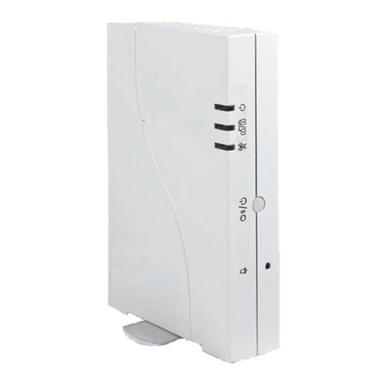
Smart Hub Indications and Connections Smart Hub Front View Microphone (for future use) Status Button Press 1 second: The system will play local status messages Press 3 seconds: Quick learn mode Press 2 minutes: Resets the Smart Hub Smart Hub Rear View Ethernet connection Power Adaptor connector SIM Card slot. -
Page 14: Leds Indication
LEDs Indication LED displays Color State Status Green Power OK AC trouble Power LED Orange Battery trouble. System set (Full Set or Part Set) rapid flash Alarm System is in entry/exit delay slow flash before unsetting/setting the system System ready Status LED Green System in Exit delay with... -
Page 15: Device Mounting Considerations
Device Mounting Considerations Mounting Considerations for Smart Hub For optimum installation of the Smart Hub and detectors, make sure to follow the recommendations for the mounting location, as illustrated below. Min. 3 ft (1m) Min. 3 ft (1m) Min. 3 ft (1m) Min. -
Page 16: Wireless Signal Loss Through Certain Building Materials
Wireless Signal Loss through certain building materials It is helpful to identify certain building materials that may be the cause of loss of signal strength and to make sure that the area around the Smart Hub is free of such materials, as much as possible. If signal interference is experienced, you may want to consider moving the Smart Hub. -
Page 17: Mounting Considerations For Detectors
Mounting considerations for Detectors Wood & Metal Frame Wood Frame Max. 0.4 in (1cm) Metal Frame (possible 30% signal loss) For metal frame - wood or plastic spacer is required Max. 0.2 in (0.5cm) WiComm Reference Manual... -
Page 18: Mounting Considerations For Pir Detectors
Mounting considerations for PIR detectors Min. 3 ft (1m) Min. 3 ft (1m) Min. 3 ft (1m) Min. 3 ft (1m) Min. 3 ft (1m) Note: Place the detector just a foot (30 cm) or so lower than the ceiling. To provide maximum coverage, the detector should be placed in a corner facing away from any windows and ideally towards the entrance of the room, or, follow the height specified in their Installation Instructions. -
Page 19: Activating The Battery Of Door / Window Detector
Activating the Battery of Door / Window Detector Activating the battery Remove the red battery isolation strip to battery activate the battery. isolation strip How to Mount the Door / Window Detector Mounting with Adhesive Tape Peel the two-sided adhesive tapes from the detector and magnet and attach the detector and magnet to the mounting location. - Page 20 Mounting with Screws 1. Insert a flathead screwdriver and rotate to detach the back of the transmitter from the back bracket (A). At the mounting location, note the alignment marks for both components (B), and then install accordingly using 2 mounting screws (C). 2.
- Page 21 The mark on the magnet’s case must be aligned with the mark on the transmitter’s case. Max. 0.4 in (1cm) WiComm Reference Manual...
-
Page 22: Activating The Batteries Of The Pir Detector
Activating the Batteries of the PIR Detector Remove the red battery battery isolation strips to isolation activate the batteries. strips How to Mount the PIR Detector Mounting with Adhesive Tape Peel the two-sided adhesive tapes from the detector and attach the detector to the mounting location. - Page 23 Mounting with Screws 1. Release screw using a Phillips screwdriver. 2. Insert a flathead screwdriver into the slot and push to remove cover. WiComm Reference Manual...
- Page 24 3. Open the knockout holes of the mounting bracket, and use them as a template for mounting. Corner Mounting Surface Mounting WiComm Reference Manual...
- Page 25 4. Slide the PIR detector downward onto the mounting bracket. 5. Insert and fasten the screw into the hole located at the bottom of the detector to lock the detector to the mounting bracket. WiComm Reference Manual...
-
Page 26: Wireless Device Allocation
Wireless Device Allocation The initial installation of the system must be performed using the RISCO Express Wizard. If additional accessories are purchased at a later stage, they must be allocated (“enrolled”) to the system using the method described below, and not using the RISCO Express Wizard. -
Page 27: Table Of Additional Devices Allocation Procedure
Table of Additional Devices Allocation Procedure Wireless Device Transmission procedure PIR Detectors: • Motion Detector- Press the tamper switch for 3 seconds. PIR camera • Motion Detector Pet camera Door/Window Press the tamper switch for 3 seconds. Detector Remote Keyfob Press for at least 2 seconds LCD Keypad... -
Page 28: Logging Into The User Web & App
1. Enter your email address and password selected at the start of registration. 2. For the required “PIN Code” enter your assigned 4-digit Master User code selected during the “User & Codes” stage of the RISCO Express Wizard. WiComm Reference Manual... -
Page 29: Setting The Time Zone
Setting the Time Zone 1. Click the System Settings link in the left-hand column of the screen. 2. Click the Date and Time button; the SYSTEM SETTINGS page displays the current time zone and time format. 3. Make the required changes. 4. - Page 30 4. Select “+Add New CP User” to add a user that can control the system only via a keypad, if installed. WiComm Reference Manual...
- Page 31 5. Click the arrow to the right of “Authority Level” and select one of the following: User – used to set/unset the system. • Set Only – used only to set the system. • Cleaner – used only for one-time setting and unsetting. •...
-
Page 32: Change Zone Labels
Change Zone Labels 1. Click the Detectors link in the left-hand column of the screen. 2. Select the detector you wish to edit. 3. Select the pencil icon next to the zone label. 4. Edit the zone label. 5. Click Close. WiComm Reference Manual... -
Page 33: User Operations
User Operations This chapter describes the user-operational procedures for the WiComm. User Operational Devices WiComm can use several operating devices. The most typical ones are listed below. 4 Button Remote Keyfob Using the 4-button remote control you can set/unset and receive system status messages. Smartphone App For Android and iOS, use the iRISCO Smartphone app for system operation and... -
Page 34: Full Setting
FULL SETTING FULL SETTING is used when the protected premises is vacated, and all system detectors are therefore activated. After setting, you must exit via the designated exit door within the designated “exit delay” (60 seconds) Press From the Security screen of the App press the icon on the top of the screen. -
Page 35: Stay / Partial Setting
STAY / PARTIAL Setting STAY/PARTIAL Setting sets only part of the premises while enabling people to remain on another unset part of the premises. Press From the Security screen of the App press the YELLOW icon on the top of the screen. Press From the Security tab, click the YELLOW square under the PARTIAL OR STAY (... -
Page 36: Area Setting
AREA Setting In some cases, you may want to divide your property into Areas that can be set and unset separately. For example, if you have a Home Office. There can be up to 3 areas. Each area can be managed as a separate security system that can be set and unset individually, regardless of the condition of the other. -
Page 37: Unsetting
Note: To set an AREA from the Remote Keyfob please contact your dealer. Unsetting Unsetting your system causes the detectors not to trigger an alarm when violated. When entering a set site, a 30 seconds entry delay countdown begins, during which time you must unset the system in order not to activate alarms. The following table describes how to unset your system when set or when silencing an alarm. -
Page 38: Replacing Batteries
Replacing Batteries Service Mode Since the wireless devices of your system are battery powered, battery replacement of these devices will be required periodically. Your Smart Hub provides you with a low battery indication for each device that is assigned to the system. -
Page 39: Battery Replacement Of Door / Window Detector
Battery Replacement of Door / Window Detector Enter Service Mode and then follow the following procedure. 1. Release screw using a Phillips screwdriver (A) and then insert a flathead screwdriver into the slot and twist to open cover (B). 2. Insert the battery while observing + - polarity. 3. -
Page 40: Battery Replacement Of Pir Detector
Battery Replacement of PIR Detector 1. Press in the tab and lift to open the battery compartment cover. 2. Insert the batteries while observing + - polarity. 3. Slide back cover into place and secure with screw. For battery replacement of other devices, refer to the specific device installation instructions. -
Page 41: 10. Technical Specifications
10. Technical Specifications Electrical Electrical power requirement 100-240V, 50/60 Hz 0.6A Power consumption (at main panel) Typical 14.4VDC 0.15A – 1.5A Backup battery 7.2V,NiMH,1.8Ah Environmental Operating Temperature -10°c – 55°c (14°F to 131°F) Physical Dimension 182mm X 135mm X 40mm Wireless Frequency 433.92 MHz, 868.65MHz, 869.525MHz,... -
Page 42: 11. Standard Compliance
11. Standard Compliance Model Description FCC-ID: JE4RW232M915 Contains FCC ID:QIPEHS6 RW232M IC: 6564A-RW232M Contains IC :7830A-EHS6 Frequency:915Mhz ,916Mhz FCC ID: JE4WL132KF1915 WL 132KF1 IC: 6564A-WL132KF1 Frequency: 915 MHz FCC ID: JE4RWX73F915 RWX73F IC: 6564A-RWX73F Frequency: 915 MHz FCC ID: JE4RWX95915 RWX95P IC: 6564A-RWX95 Frequency: 915 MHz... - Page 43 Model Description Contains FCC ID: JE4STAMP915 WL S42 IC: 6564A-WLS42 Frequency: 915 MHz FCC ID: JE4RWT6G915 RWT6G IC: 6564A-RWT6G915 Frequency: 915 MHz FCC ID: JE4RWT6F915 RWT6F IC: 6564A-RWT6F Frequency: 915 MHz WiComm Reference Manual...
-
Page 44: Red Compliance Statement
RED Compliance Statement: (Models: RW232M8B, RW232M8C, RW232M87) Hereby, RISCO Group declares that this equipment is in compliance with the essential requirements and other relevant provisions of Directive 2014/53/EU. For the CE Declaration of Conformity please refer to our website: www.riscogroup.com. - Page 45 (2) This device must accept any interference received, including interference that may cause undesired operation. Changes or modifications to this equipment which are not expressly approved by the party responsible for compliance (RISCO Group's.) could void the user's authority to operate the equipment. WiComm Reference Manual...
- Page 46 RISCO, for a period of (i) 24 months from the date of connection to the RISCO Cloud (for cloud connected products) or (ii) 24 months from production (for other products which are non-cloud connected), as the case may be (each, the “Product Warranty Period”...
- Page 47 CONSEQUENTIAL DAMAGES, EVEN IF THEY WERE FORESEEABLE OR RISCO HAS BEEN INFORMED OF THEIR POTENTIAL. RISCO does not install or integrate the product in the end user security system and is therefore not responsible for and cannot guarantee the performance of the end user security system which uses the product.
- Page 48 Contacting RISCO Group RISCO Group is committed to customer service and product support. You can contact us through our website www.riscogroup.com or via the following: Belgium (Benelux) Israel United Kingdom Tel: +32-2522-7622 Tel: +972-3-963-7777 Tel: +44-(0)-161-655-5500 support-be@riscogroup.com support@riscogroup.com support-uk@riscogroup.com China (Shanghai)
Need help?
Do you have a question about the WICOMM RW232M and is the answer not in the manual?
Questions and answers