Seca 664 Service Manual
Hide thumbs
Also See for 664:
- Manual (369 pages) ,
- Instruction manual and guarantee (78 pages) ,
- Service manual (75 pages)
Table of Contents
Advertisement
Variants:
6641321004
6641321104
6641321134
6641321364
6642521004
6642521104
6642521134
6657021004
6657021009
6657021094
6657021099
6657021194
6657021199
6657021244
6657021249
6657521004
6657521009
6657521094
6657521099
6657521194
6657521199
Content:
Description chipcard module
Description NEC I Elektronik
Description of faults
Function diagram
Calibration
PC configuration program
Cable plan
Cable plan chipcardreader
Replacement
Spare parts
Manual number:
17-05-01-292-L
Service Manual
for seca 664 / 665
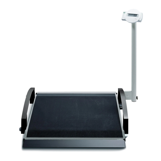
Description:
Electronic wheelchair scale, collabsible, vertical stand up and easily
manoeuvrable. Pre tara function with three adjustable values with chipcardreader.
Turnable display and operating housing.
Service Manual Number
17-05-01-292-L
Valid as of:
30-34-00-685
30-34-00-779
30-34-00-588 d
25-02-02-209 a
30-34-00-603
30-34-00-672 b
08-02-06-022 c
08-02-06-025
30-34-00-673 d
30-34-00-669 k
01.03.2011
Advertisement
Table of Contents

Related Manuals for Seca 664


Summary of Contents for Seca 664
- Page 1 Service Manual Variants: for seca 664 / 665 6641321004 6641321104 6641321134 6641321364 Service Manual Number 6642521004 6642521104 17-05-01-292-L 6642521134 Valid as of: 01.03.2011 6657021004 6657021009 6657021094 6657021099 6657021194 Description: 6657021199 Electronic wheelchair scale, collabsible, vertical stand up and easily 6657021244 manoeuvrable.
- Page 2 Brief Description of the Chip Card Module Introduction The chip card module belongs to the family of seca electronic modules and is used to write data to and to read data from chip cards. It works together with the extended display module which contains the operating functions for chip card handling.
- Page 3 30 General bus fault 32 Command buffer full 50 Rom checksum fault 52 Chip card not valid 100 Note, chip card saving Time base From the quartz’s 4.19MHz a time base is derived which controls all timed processes in the scale. These are, for instance, various timeouts.
- Page 4 If, instead of the original seca power supply unit, a power supply unit is used that supplies an output voltage of more than 12V, the electronics can be destroyed. Warning: There are many 12V power supply units that supply more than 12V if there is no sufficient load on them.
- Page 5 Service manual Description of faults Please refer to the operating instructions to make sure that scale malfunctions are not caused by operation faults. Should any faults occur, the following table will help you to identify the cause of the fault. Fault description Possible cause Remedy...
- Page 6 Service manual Description of faults Fault description Possible cause Remedy Er:X:14 Fault in the kg value Wrong coefficients in the module’s ROM, reprogram and readjust the calculation scale Er:X:15 Recalibration fault Reference weight outside the permitted range or operating fault ...
- Page 8 General: General: Seca scales with modular electronics are fitted with a software-controlled calibration device that is operated using the existing controls. This device can be used to recalibrate the scales or to set the scales to different GAL values. During development of the calibration device, special attention was paid to the following requirements: •...
- Page 9 Vogel & Halke File: 00603_e1.doc seca Created on: 30.06.1998 Printed on: 07.07.1999 Holger Panier / SE Pressing the kg/lbs key for less than 1.5 seconds causes the weight shown on the display to be increased or decreased by 10 g (depending on the mode currently selected). As the resolution of the display is lower, the displayed value will not necessarily be increased or decreased each time the kg/lbs key is pressed.
- Page 10 Vogel & Halke File: 00603_e1.doc seca Created on: 30.06.1998 Printed on: 07.07.1999 Holger Panier / SE Summary of a typical recalibration sequence: Summary of a typical recalibration sequence: Action carried out by the user Result The scales are switched off.
- Page 11 1 (2) PC configuration program page Instructions for PC-based configuration PC-based configuration is used for diagnosis or recalibration of all seca scales with modular electronics. The following equipment is required: • PC with serial interface (RS -232) • seca software 'SERVA”...
- Page 12 2 (2) PC configuration program page Standard case Connection to the existing display unit port. The display can instead be connected to the second modular socket of the service module. DMS module with integrated display 08-06-18-082 If there is no modular socket on the back of the PCB, retrofit one.
- Page 15 Service Manual Replacement instructions seca 664, 665 Removing the power supply unit / ESD protection measures (Page 7) The power supply unit must not be connected. We urgently recommend that you remove the battery pack before starting any work on the unit: Remove the 2 screws (Item 7.11) and the battery cover (Item 7.12).
- Page 16 Service Manual Replacement instructions Removing the joint connection from the display housing (Page 12) Dismantle the display housing as described under 1.3. Remove the screws (Item 12.23). Disengage the housing (Item 12.22) from the snap-in connection with the tilt stand (Item 12.20). Remove the screws (Item 12.21) and lift off the tilt stand.
- Page 17 Service Manual Replacement instructions Warning: Carefully thread the load cell cable out of the frame tubes. (For unsoldering see 2.1.1). Remove the spacer disks (Item 6.5) and the screws (Items 6.6, 6.7). Warning: The longer screws (Item 6.7) are used to screw the load cell cover tight. Removing the adjusting feet (Page 6) Screw out the complete foot (Items 6.14, 6.15) and screw off the knurled nut (Item 6.15).
- Page 18 Service Manual Replacement instructions Assembly (the references to pages and items relate to the replacement instructions drawing, Pages 5-13) Assemble in reverse order of disassembly. Please note the following points: 1. Glue on the mat (Page 11) Mounting the following parts before you glue on the mat: The 4 rubber elements and washers (Item 11.3) with the screws (item 11.5).
- Page 28 Spare parts list 664 / 665 Wheelchair scale with NEC- I 2 - module Base frame Item Article no. Designation Price stage 02-00-03-311-509 Baseframe comp. 02-02-03-095-009 Frame 02-03-03-091-009 Platform plate 02-03-03-283-009 Platform insert 02-03-03-093-009 Platform reinforcing left 02-03-03-094-009 Platform reinforcing right...
- Page 29 Spare parts list 664 / 665 Wheelchair scale with NEC- I 2 - module Column Item Article no. Designation Price stage 04-02-06-030- 509 Column compl. 04-02-06-223-009 Column 01-03-06-207-009 Bracket 01-08-03-357-009 Threaded axle 01-08-05-242-009 Lock screw 01-08-03-376-009 Bold 50-90-00-544-009 Knurled knob...
- Page 30 Spare parts list 664 / 665 Wheelchair scale with NEC- I 2 - module Display Item Article no. Designation Price stage 34-02-01-001-009 Display housing 34-02-01-013-509 Display housing for chipcard model 34-02-04-339-009 Tilt stand 34-02-04-342-009 Membrane keyboard 34-02-04-373-009 Membrane keyboard multiple range...
- Page 31 Spare parts list 17.03.2011/MRE 4 (5) 30-34-00-669 k...
- Page 32 Spare parts list 17.03.2011/MRE 5 (5) 30-34-00-669 k...
Need help?
Do you have a question about the 664 and is the answer not in the manual?
Questions and answers