Advertisement
Quick Links
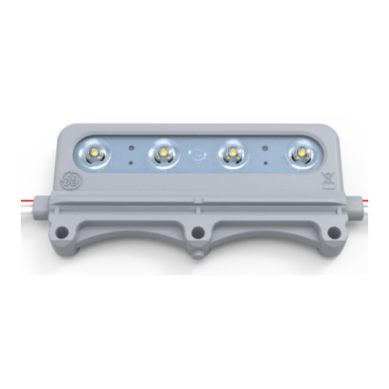
Tetra
PowerStrip Snap DS
®
LED Lighting System
GEDS71-3, GEDS65-3, GEDS57-3, GEDS50-3,
GEDS41-3, GEDS32-3
BEFORE YOU BEGIN
Read these instructions completely and carefully.
Българската версия на инструкциите за инсталаця
BG
и информация за безопасност могат да бъдат
намерени на следния адрес: https://products.
currentbyge.com/eu
Návod k montáží a bezpečnostní informace v češtině
CS
najdete zde: https://products.currentbyge.com/eu
Den danske version af installationsvejledningen
DA
og sikkerhedsoplysninger kan findes på følgende
placering: https://products.currentbyge.com/eu
Die deutsche Version der Installationsanleitung und
DE
Sicherheitsinformationen finden Sie in folgendem
Verzeic: https://products.currentbyge.com/eu
Μπορείτε να βρείτε την ελληνική εκδχή των οδηγιών
EL
νγκατάστασης και των πληροφοριών ασφάλειας στην
εξής τοποθεσία: https://products.currentbyge.com/eu
La versión española de las instrucciones de instalación
ES
y la información sobre seguridad puede encontrarse
en la siguiente ubicación: https://products.
currentbyge.com/eu
Eestikeelse paigaldusjuhendi ja ohutusnñuded leiate
ET
aadressilt: https://products.currentbyge.com/eu
Asennusohjeiden ja turvallisuustietojen
FI
suomenkielinen versio löytyy seuraavasta paikasta:
https://products.currentbyge.com/eu
For the latest North American install guides for your product go to: https://products.gecurrent.com/led-signage-lighting
For the latest European install guides for your product go to: https://products.gecurrent.com/eu/led-signage-lighting
Prepare Electrical Wiring
Electrical Requirements
• Limited to use in dry and damp locations.
• The grounding and bonding of the LED Driver shall be
done in accordance with National Electric Code (NEC)
Article 600.
• Follow all National Electric Codes (NEC) and local codes.
• These products are only suitable for connection to a
circuit from a Class 2 power source. These products
have not been evaluated for use when connected to a
power source that does not comply with Class 2 voltage
and energy limited supplies.
La version française des instructions d'installations
FR
et information de sécurité est disponible à l'adresse
suivante: https://products.currentbyge.com/eu
Hrvatska verzija priručnika za ugradnju i sigurnosnih
HR
informacija nalazi se na sljedečoj lokaciji: https://
products.currentbyge.com/eu
A telepítési útmutató és a biztnosági információk
HU
magyar nyelvű változata az alábbi címen található:
https://products.currentbyge.com/eu
La versione italiana del manuale di installazione e
IT
sicurezza può essere reperita nella seguente sezione:
https://products.currentbyge.com/eu
Lietuvišką diegimo instrukcijos ir saugos informacijos
LT
versiją galima rasti šioje vietoje: https://products.
currentbyge.com/eu
Uzstādīšanas instrukciju un drošības informāciju
LV
latviešu valodā var atrast šeit: https://products.
currentbyge.com/eu
De Nederlandse versie van de installatie-instructies
NL
en veiligheidsinformatie kan op de volgende locatie
worden gevonden: https://products.currentbyge.
com/eu
FOR UL ONLY
Polską wersję instrukcji instalacji oraz informacje
PL
dotyczące bezpieczeństwa można znaleźć w
następującej lokalizacji: https://products.currentbyge.
com/eu
A versão em Português das instruções de instalação e
PT
das informações de segurança pode ser encontrada
na seguinte localização: https://products.currentbyge.
com/eu
Versiunea în limba română a instrucţiunilor de
RO
instalare şi a informaţiilor de siguranţă pot fi găsite la:
https://products.currentbyge.com/eu
Ni hittar den svenska versionen av
SV
installationsanvisningarna och säkerhetsinformationen
på följande plats: https://products.currentbyge.com/eu
Previdnostna opozorila in varnostne informacije so na
SL
zadnji strani vodnika za namestitev. Pred začetkom
namestitve izdelka jih skrbno preberite: https://
products.currentbyge.com/eu
Slovenskú verziu montažnej príručky a
SK
bezpečnostnŷch instrukcií nájdete na nasledujúcej
lokalite: https://products.currentbyge.com/eu
Save These Instructions
Use only in the manner intended by the
manufacturer. If you have any questions, contact the
manufacturer.
RETROFIT SIGN CONVERSION LED KIT FOR USE ONLY
IN ACCORDANCE WITH KIT INSTRUCTIONS.
KIT IS COMPLETE ONLY WHEN ALL PARTS REQUIRED
BY THE INSTRUCTIONS ARE PRESENT.
TROUSSE DE CONVERSION À DEL POUR LA
MODERNISATION DES ENSEIGNES
À UTILISER CONFORMÉMENT AU GUIDE D'INSTALLATION.
Installation Guide
EN
SIGN271 | A-1025384
24
Volt
Advertisement

Related Manuals for Daintree GE current Tetra PowerStrip Snap DS


Summary of Contents for Daintree GE current Tetra PowerStrip Snap DS
- Page 1 Installation Guide SIGN271 | A-1025384 Tetra PowerStrip Snap DS ® Volt LED Lighting System GEDS71-3, GEDS65-3, GEDS57-3, GEDS50-3, GEDS41-3, GEDS32-3 BEFORE YOU BEGIN Read these instructions completely and carefully. Българската версия на инструкциите за инсталаця La version française des instructions d’installations Polską...
- Page 2 Tetra PowerStrip Snap DS Installation Guide ® WARNING / AVERTISSEMENT RISK OF ELECTRIC SHOCK RISQUES DE DÉCHARGES ÉLECTRIQUES ∙ ∙ Turn power off before inspection, installation or removal. Coupez l’alimentation avant l’inspection, l’installation ou le déplacement. ∙ ∙ Properly ground GE power supply enclosure. Assurez-vous de correctement mettre à...
- Page 3 Tetra PowerStrip Snap DS Installation Guide ® Components Measure Point Optional UL certified 18 AWG (0.82 mm ) supply wire Tetra Snap 8ft. Rail (GEDSRL08-3) UL certified 22-14 AWG (0.33-2.08 mm ) wire ® connectors or 18-14 AWG (0.82-2.08 mm ) inline/ Tetra Snap Socket Endcap (GEDSSE-3)
- Page 4 Tetra PowerStrip Snap DS Installation Guide ® Installation Using Tetra Snap Rails ® Rail (mounted vertically) Sign SNAP! Measure and cut Tetra® Snap Rail to appropriate Align peg on top of the light module with hole length to fit into sign. For retrofitting a sign, see on top of the Tetra Snap Rail and push module ®...
-
Page 5: Installation Options
Tetra PowerStrip Snap DS Installation Guide ® Installation Options Alternative Mounting The modules may be attached to any Mount modules structural member of the sign using one to sign structure. #6 or M3 screw or 1/8” rivet. Ensure the module’s lip is tight against rail. 2 fasteners may be used for NOTE: Modules may be damaged by... - Page 6 Tetra PowerStrip Snap DS Installation Guide ® Using Tetra Snap Socket Endcap ® Tetra Snap Nominal LFL ® Rail Length Requirements Tetra Snap Socket Endcap Nominal T12 Nominal Rail Tube Length Cut Length 1.5 ft. 15” (381.5mm) 2 ft. 21” (533.1mm) #8 screw 2.5 ft.
-
Page 7: Electrical Connections
Tetra PowerStrip Snap DS Installation Guide ® Electrical Connections Last module Power First supply module AC line Connect modules using twist-on Connect output side of wire connectors or in-line (IDC) power supply to first connectors. Join white wires module. Connect the together and red striped wires red stripe wire (+) of the together. -
Page 8: Troubleshooting
Tetra PowerStrip Snap DS Installation Guide ® Troubleshooting Symptom Solution • Row of modules does not light Check wire connections to power supply to ensure red stripe-to-red and white-to-black or blue connections. • Check row-to-row polarity connections. • Sign does not light Check input and output voltage and check power supply input/output connections.