Table of Contents
Advertisement
Quick Links
Operating and
Service Manual
30/20S1G18B
Model
10046372
Part Number
Serial Number
EXPORT CONTROLLED DATA.
These commodities, technology or software are controlled for export in accordance with the U.S. Export
Administration Regulations. Diversion contrary to U.S. law is prohibited.
160 School House Road, Souderton, PA 18964 • 215-723-8181 • Fax 866-859-0582 • www.arworld.us
Advertisement
Table of Contents

Subscribe to Our Youtube Channel
Related Manuals for AR 30/20S1G18B


Summary of Contents for AR 30/20S1G18B
- Page 1 Operating and Service Manual 30/20S1G18B Model 10046372 Part Number Serial Number EXPORT CONTROLLED DATA. These commodities, technology or software are controlled for export in accordance with the U.S. Export Administration Regulations. Diversion contrary to U.S. law is prohibited. 160 School House Road, Souderton, PA 18964 • 215-723-8181 • Fax 866-859-0582 • www.arworld.us...
- Page 3 REGULATION (EC) 1907/2006 OF THE EUROPEAN PARLIAMENT AND OF THE COUNCIL of 18 December 2006 concerning the Registration, Evaluation, Authorization and Restriction of Substances of Very High Concern Chemicals (SVHC) Supporting documentation is held by AR RF/Microwave Instrumentation’s Quality department in Pennsylvania, United States. Place of issue:...
- Page 5 Instructions for European EMC Conformity WARNING It is the responsibility of the user of this equipment to provide electromagnetic shielding, filtering and isolation which is necessary for EMC compliance to Directive 2014/30/EU. The equipment must therefore be operated in a shielded area which provides a sufficient level of attenuation to meet the radiated emissions and immunity specifications.
- Page 7 The caution symbol denotes a potential hazard. Attention must be given to the statement to prevent Your AR equipment may have more than one power supply cable. Use damage, destruction, or harm. only approved power cable(s). If you have not been provided with a Dangerous voltages are present.
- Page 8 EQUIPMENT CONTAINING LASERS risk of serious injury due to unsafe AR Field Probes (FL/PL Series) and Field Analyzers (FA product handling should be a fundamental Series) are Class 1 laser products containing embedded consideration every user.
- Page 9 Zur Vermeidung von Personen- oder Sachschäden gilt BEVOR SIE DAS GERÄT ANSCHLIESSEN es, die Hinweise zu beachten. Ihre AR-Ausrüstung hat möglicherweise mehr als ein Stromversorgungskabel. Gefährliche elektrische Spannungen sind vorhanden. Verwenden Sie nur zugelassene Stromkabel. Falls Sie kein Stromkabel oder Höchste Vorsicht ist geboten.
- Page 10 Die meisten Geräte müssen während des Versands, der Montage und des Gebrauchs LASER-INFORMATION transportiert werden. Jeder Nutzer sollte sich AR - Feldsonden (FL/PL-Serie) und Feldanalysatoren (FA-Serie) über das Risiko von schweren Verletzungen sind Laserprodukte der Klasse 1 mit eingebetteten Klasse-4- durch unsachgemäße...
- Page 11 électrode de mise à la Votre équipement AR peut disposer de plus d’un câble d’alimentation terre de protection. électrique. Utilisez uniquement un ou des câbles d’alimentation approuves.
- Page 12 éliminer le risque injustifié de blessures causées par le levage est fournie par les méthodes de travail de NIOSH (publication Les sondes de champ AR (série FL/PL) et les analyseurs de n° 94-110) disponibles sur : champ (série FA) sont des produits laser de classe 1 contenant des lasers intégrés de classe 4.
- Page 13 Er zijn gevaarlijke elektrische spanningen aanwezig. Wees uiterst voorzichtig. VOOR HET OPZETTEN VAN DE STROOM Uw AR-apparatuur kan meer dan een netvoedingskabel bezitten. Gebruik alleen goedgekeurde netvoedingskabel(s). Koopt een Wijst op een terminal aan die bedoeld is voor aansluiting netvoedingskabel die is goedgekeurd voor gebruik in uw land als u...
- Page 14 APPARAAT DAT LASERS BEVAT distributie, de assemblage en het gebruik moeten worden behandeld, moet het risico AR-terreinsondes (FL/PL-serie) en terreinanalysatoren (FA- op ernstig letsel als gevolg van een serie) zijn laserproducten van klasse 1 met ingesloten onveilige behandeling van het product een klasse 4-lasers.
-
Page 15: Table Of Contents
TABLE OF CONTENTS TABLE OF CONTENTS ....................i GENERAL INFORMATION ................1 General Description ....................1 Power Supplies ....................... 1 Specifications ......................1 OPERATING INSTRUCTIONS ................ 5 General ........................5 Amplifier Front and Rear Panels................6 2.2.1 Local Control Interface ..................6 2.2.1.1. - Page 16 4.3.15 High Band Low or No Power Output (RF Test) (Schematic Diagram 10044481) ......................35 Cooling System ....................37 FIGURES Model 30/20S1G18B Front Panel ................6 Model 30/20S1G18B Rear Panel ................6 Menu Map ......................7 Typical Response @ 0dBm Input and -20 dBm Input ......... 32 Typical Gain Response from the A8 Splitter Input to the RF Output ....
- Page 17 Typical A1 Pre-Amp Response ................37 TABLES RS-232 Port Settings ....................9 RS-232 (DCE) Port Pinout Diagram DB-9 Female ..........9 Fiber-Optic Port Settings ..................9 Relationship between 30/20S1G18B Multi-Band Amplifier Controls and Remote Communication ....................10 States ........................16 Faults ........................17...
-
Page 19: General Information
A7 and output modules (A9 & A10). PS3 also supplies +21.5V to the low band fans. SPECIFICATIONS Refer to the AR Data Sheet at the end of this section for detailed specifications. All voltage measurements referenced in this manual are Direct Current (DC) unless stated otherwise. Rev A... - Page 20 Model 30/20S1G18B Rev A...
-
Page 21: Specifications
Specifications Features The Model 30/20S1G18B is a portable, self- This model is designed to have low spurious 30/20S1G18B contained, air-cooled, dual-band, broadband, signals, exhibit very good linearity, and is ex- completely solid-state amplifier designed for tremely load tolerant which enables it to be used... - Page 22 THIRD ORDER INTERCEPT: 50 dBm typical NOISE FIGURE: 10 dB typical HARMONIC DISTORTION: Minus 20 dbc max at 30 watts (0.7-6.0 GHz) PRIMARY POWER (Selected Automatically): 90-264 VAC, 50/60 Hz, single phase, 300 watts maximum 30/20S1G18B TYPICAL POWER OUTPUT WITH 0.7-6.0GHz BAND SELECTED...
- Page 23 90-264 VAC, 50/60 Hz, single phase, 600 watts maximum 30/20S1G18B TYPICAL POWER OUTPUT WITH 6.0–18.0GHz BAND SELECTED To order AR Products, call 215.723.8181. For an applications engineer call:800.933.8181. Direct to Service call: 215.723.0275 or email: service@arworld.us For Faxing Orders:866.859.0582 (Orders Only Please) info@arworld.us...
-
Page 25: Operating Instructions
2. OPERATING INSTRUCTIONS GENERAL Operation of the Model 30/20S1G18B broadband amplifier is simple. The input signal, whether swept or fixed in frequency, is fed into the jack marked INPUT and the amplifier output signal is taken from the jack labeled OUTPUT. The unit is turned ON by activating the power switch. In the event of a unit malfunction, protection is provided by a circuit breaker located in the AC input receptacle. -
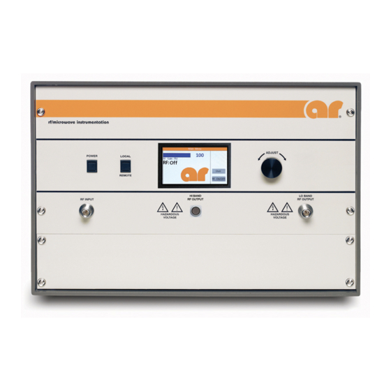
Page 26: Amplifier Front And Rear Panels
Band Amplifier’s power is on or off. The main power supply fans are active when power is on. The LCD touch display is active as long as the main circuit breaker for the 30/20S1G18B Multi-Band Amplifier power entry module is on. -
Page 27: Menu Map
2.2.1.5 Menu Map Figure 2-3 shows the menu map for the 30/20S1G18B Multi-Band Amplifier. The screens depicted are only example screens. The actual values and settings will be different on the actual amplifier depending on user settings and operating conditions. -
Page 28: Remote Control Interface
Communicating through two or more ports at one time will cause data collisions and lost commands or queries. The Toggle switch on the control panel of a 30/20S1G18B Multi-Band Amplifier allows it to be controlled using remote communications. All remote queries will work in any Toggle switch position, but all remote commands will only work when the position is set to REMOTE. -
Page 29: Fiber-Optic Serial Communication
NOTE: This baud rate setting is shared by both the Fiber-Optic serial port and the RS-232 port. The Fiber-Optic port provides the user with the ability to optically isolate the controlling PC from the 30/20S1G18B Multi-Band Amplifier. This can be useful in an environment where RF/Microwave energy Rev A... -
Page 30: Usb Communication
This port can be used in conjunction with either an AR model IF7000 RS-232 to Fiber-Optic Interface (1200 to 9600 baud only) or an AR model IF7001 USB to Fiber-Optic Interface (19200 baud only). Note that these devices use SMA connectors so a fiber-optic cable is needed with ST connectors on one end and SMA connectors on the other. -
Page 31: Ethernet Communication
Lantronix Ethernet devices. This list of found devices will include any connected AR Ethernet devices. By selecting one of the connected devices from the list, its IP address and subnet mask can be changed along with a number of other settings. -
Page 32: Relationship Between 30/20S1G18B Multi-Band Amplifier Controls And Remote Communication
Variables represented by wild card characters i.e. x, y, z etc. do not indicate or delimit the number of characters actually specified. Table 2-4. Relationship between 30/20S1G18B Multi-Band Amplifier Controls and Remote Communication AC Power and... -
Page 33: Power On/Off
Model 30/20S1G18B 2.4.6.1 Power On/Off This command controls the power on/off state of the 30/20S1G18B Multi-Band Amplifier. Syntax: POWER:x Parameters: State(x): OFF = power off ON = power on Response Format: None (No query for this command) Example: To turn the power on, send the following command: POWER:ON<LF>... -
Page 34: Reset Faults
None Response Format: None (No query for this command) Example: To clear any faults, send the following command: RESET<LF> 2.4.6.4 Level Adjust This command sets the RF gain of the 30/20S1G18B. Syntax: LEVEL:xy Parameters: Parameter(x): GAIN = RF Gain Value(y):... -
Page 35: Identity
Query only (always requires a ? character) Response Format: f,m,n,<LF> Where: f = manufacturer m = model designation n = firmware revision Example: To get the identity of the 30/20S1G18B Multi-Band Amplifier, send the following command: *IDN?<LF> AR-RF/MICROWAVE-INST,XXXXXXXX,1.0<LF> Response: 2.4.6.6 IO Board Firmware Revision Query to get the firmware revision of the I/O Board. -
Page 36: State
They can be 0 to 9 or A to F. Each hexadecimal character represents a 4-bit binary number. This 4-bit number is a bit pattern which contains information about the state of the 30/20S1G18B Multi-Band Amplifier. The definitions of these bit positions can be found in the table below. -
Page 37: Rf Gain
Syntax: RFG? Parameters: None Response Format: RFG=<space>x<LF> Where: x = 0000 to 0100 Example: To find out the RF gain of the 30/20S1G18B Multi-Band Amplifier, send the following query: RFG?<LF> Response: RFG=<space>0075<LF> (75% Gain) 2.4.6.9 Faults Query to find the faults that have occurred with the 30/20S1G18B Multi-Band Amplifier. -
Page 38: Operating Hours (Rf On)
Model 30/20S1G18B Example: To find out what faults have occurred, send the following query. FSTA?<LF> Response: FSTA= 0002<LF> (Interlock Fault) 2.4.6.10 Operating Hours (RF On) Query to get the RF On operating hours. Syntax: Parameters: None Response Format: OH=x<LF> Where: x = 0 to 100000 Units are Hours. -
Page 39: Sbb (Piggyback) Firmware Revision
Model 30/20S1G18B 2.4.6.12 SBB (Piggyback) Firmware Revision Query to get the firmware revision of the piggyback SBB assembly. Syntax: *SBB? Parameters: None Query only (always requires a ? character) Response Format: SBB_SW_REVx<LF> Where: x = firmware revision Example: To get the firmware rev. of the piggyback SBB assembly, send the following command: *SBB?<LF>... -
Page 40: Ac Power-On Defaults
Response: DEFAULT:LEVEL:GAIN75<LF> 2.4.7 Interlocks The 30/20S1G18B Multi-Band Amplifier has one interlock circuit that is wired to the rear panel Safety Interlock connector. This interlock requires a normally closed external circuit to allow the unit to function. 2.4.7.1 Inhibit Interlock This interlock circuit inhibits RF amplification by disabling the low level (A1) and Power (A2 & A3) amplifier stages. -
Page 41: Theory Of Operation
3. THEORY OF OPERATION INTRODUCTION The Model 30/20S1G18B RF amplifier consists of a 0.7–6.0 GHz RF amplifier assembly and a 6.0 to 18 GHz amplifier assembly. The power supply section consists of an AC input filter, a switch, three switching power supplies, and a regulator circuit. -
Page 42: A9-A10 Output Power Amplifier
Model 30/20S1G18B 3.2.3 A9-A10 Output Power Amplifier The output power amp is assembled on thin film substrates. The GaN devices, 90˚ quad couplers and bias board are the same as the driver amp. The gain should be about 0.5dB less than the driver amp. It delivers approximately 15-20 watts of RF power. -
Page 43: Power Supply
Model 30/20S1G18B POWER SUPPLY The Model 30/20S1G18B contains three switching power supplies. The input voltage range to the power supply is 90–264 VAC, 47-440Hz, selected automatically. PS1 is a multiple output supply used for the low band amplifier (0.7-6.0 GHz) and high band amplifier (6–18 GHz). -
Page 44: Control System
Model 30/20S1G18B CONTROL SYSTEM 3.5.1 A3 Control/Fault Board (Schematic 10025460) The A3 Control/Fault board consists of two 16-bit microcontrollers and about nine other ICs that monitor and indicate the status of the amplifier. Power is supplied using only a single 5-volt power supply. The board... -
Page 45: Maintenance
4. MAINTENANCE GENERAL MAINTENANCE INFORMATION The Model 30/20S1G18B requires very little maintenance since it is a relatively simple instrument. It is built with etched circuit wiring and solid state devices that will ensure long, trouble free life. However, should trouble occur special care must be taken in servicing to avoid damage to the devices or the etched circuit board. -
Page 46: Troubleshooting
GaN/GaAs FETs and other ESD-sensitive devices. Troubleshooting the Model 30/20S1G18B in a logical manner can speed the solution to a problem. The settings of potentiometers (pots), capacitors (caps), or other variables should not be disturbed until other problems have been eliminated. -
Page 47: Power On Indication Doesn't Display On Front Panel Vacuum Fluorescent Display (Vfd) When Power Switch Is Depressed (Schematic Diagram 10046710)
<0.1V when S1 is depressed. S1 is normally open; it is closed only when it is depressed. The amplifier should change state every time the POWER switch is depressed. 8. If all voltages are correct and the unit still does not operate, contact AR to arrange for repair or replacement of the A14 Control Panel. -
Page 48: Thermal Fault-Lo Band (Schematic Diagram 10046710)
Interlock Fault (Schematic Diagram 10046710) The Model 30/20S1G18B is equipped with an interlock connector, which is located on the rear panel. The interlock circuit can be used to sense the openings of doors to screen rooms, test chambers, and so forth, and to turn off RF energy when these doors are opened. -
Page 49: Liquid Coolant
Model 30/20S1G18B 4.3.6 Liquid Coolant 1. If there is a coolant temperature fault, check ambient temperature (too high or too low). If within spec, check that the fans on the radiator and rear of the amp are operational. 2. If flow fault, check the coolant level, then check quick disconnect. -
Page 50: High Band Amplifier Faults (Dc Test) (Schematic Diagram 10046710)
Low Band Low or No Power Output (DC Tests) (Schematic Diagram 10044492) All indicators on the Model 30/20S1G18B are normal, the front panel vacuum fluorescent display (VFD) reads Power On, and the cooling fans (B5 and B6) are operating. 1. Check the position of the RF Gain control—is it set to maximum gain? 2. -
Page 51: Hi Band Low Or No Power Output (Dc Tests) (Schematic Diagram 10044492)
Hi Band Low or No Power Output (DC Tests) (Schematic Diagram 10044492) All indicators on the Model 30/20S1G18B are normal, the front panel vacuum fluorescent display (VFD) reads Power On, and the cooling fan B1 is operating. 1. Check the position of the RF Gain control—is it set to maximum gain? 2. -
Page 52: Lo Band Low Or No Power Output (Rf Test) (Schematic Diagram 10044492)
Model 30/20S1G18B 4.3.14 Lo Band Low or No Power Output (RF Test) (Schematic Diagram 10044492) NOTE: The DC Tests specified in Section 4.3.10 should be completed before conducting the RF tests specified in the following sections. 1. The Lo Band (0.7-6.0 GHz) typical gain response at 0 dBm input and -20 dBm input is shown in Figure 4-1. -
Page 53: Typical Quad Amplifier Response
Model 30/20S1G18B 3. If the gain is slightly low (i.e., several dB below typical), try disconnecting the input and output cables from the A7, A9 & A10 Quad Amps and checking the individual gain. Typical Quad Amp response is shown in Figure 4-3. -
Page 54: Typical 4-Way Splitter Insertion Loss And Return Loss
Model 30/20S1G18B 5. A typical Two-Way Splitter insertion loss is shown in Figure 4-5. The unused ports must be terminated when checking the insertion loss. Typical combined port return loss is shown in Figure 4-5. -5.5 -6.0 -6.5 -7.0 IL J4 IL J3 -7.5... -
Page 55: High Band Low Or No Power Output (Rf Test) (Schematic Diagram 10044481)
Model 30/20S1G18B 4.3.15 High Band Low or No Power Output (RF Test) (Schematic Diagram 10044481) 1. The High Band (6.0 to 18.0 GHz) typical gain response at 0dBm input and –20dBm input is shown in Figure 4-7. The actual gain may vary considerably from that shown in Figure 4-5, but should be > 43 dB. -
Page 56: Output Amplifier Gain
Model 30/20S1G18B 3. If the test in step 2 shows an abnormal reading, the A3 20 watt output amplifier module should look like: Figure 4-9. Output Amplifier Gain If the A3 20-watt module is normal, check the response of the A2 Driver Amp. The gain should be approximately 18-20 dB. -
Page 57: Cooling System
Model 30/20S1G18B 4. If the A2 Driver Amp is normal, check the A1 Pre-Amp. The gain of the A1 Pre-Amp should be approximately 18-20 dB with the gain control at maximum. The typical A1 Pre-Amp response is shown in Figure 4-10. - Page 58 Model 30/20S1G18B Rev A...
- Page 59 These modules are not field- repairable and should never be opened outside of AR’s Microelectronics Lab. The modules in these product lines have a security label on two sides of the modules between the housing and lid/cover. If the security label is removed and or cut, the warranty of the module will be voided.
Need help?
Do you have a question about the 30/20S1G18B and is the answer not in the manual?
Questions and answers