
Subscribe to Our Youtube Channel
Related Manuals for Gantner GAT NET.Lock 7020 System


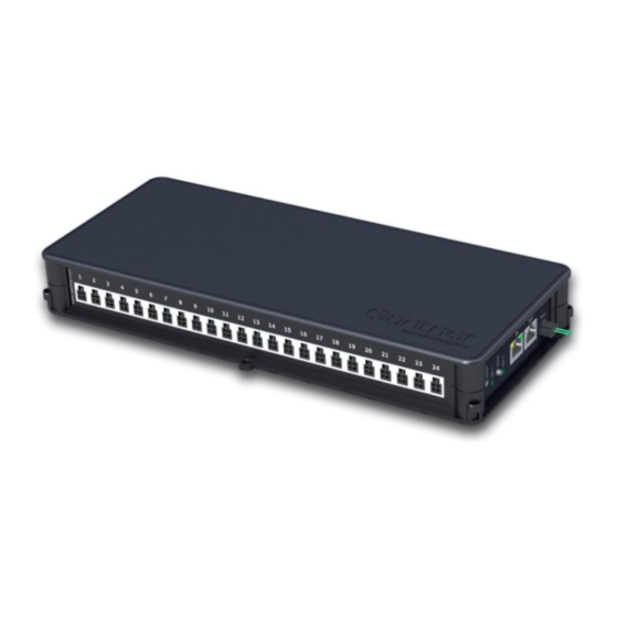
Summary of Contents for Gantner GAT NET.Lock 7020 System
- Page 1 GAT NET.Lock 7020 System Electronic RFID Locker Locks Installation, Configuration, Operation Document Version 1.2 www.gantner.com HB_GAT-NETLOCK7020--EN_12...
- Page 3 GAT NET.Lock 7020 System © Copyright 2019 GANTNER Electronic GmbH Operating instructions, manuals and software are protected by copyright. All rights are reserved. Copying, duplication, translation, installation in any electronic medium or machine-readable form in whole or in part is prohibited. The sole exception is represented by creation of a back-up copy of software for own use as a safeguard, so far as this is technically possible and recommended by us.
- Page 4 GAT NET.Lock 7020 System Important Information Dear Customer, Our aim is to ensure that our product operates with safety and to your complete satisfaction. To achieve this aim, please take this opportunity to familiarize yourself with the following guidelines. Pay attention to the safety messages in this manual. The messages are indicated by the signal words "DANGER", "WARNING", or "CAUTION", and inform you about hazardous situations and how to avoid them.
- Page 5 GAT NET.Lock 7020 System 2. Property Damage Messages Property damage messages are used to describe potentially hazardous situations that may lead to property damage. These messages have the same layout as safety messages but use the signal word "NOTICE" instead of “CAUTION”.
- Page 6 Do not attempt to repair a product after a defect, failure, or damage is detected. In addition, do not put the product back into operation. In such cases, it is essential to contact your GANTNER representative or the GANTNER support hotline.
- Page 7 Operation of this equipment in residential area is likely to cause harmful interference in which case the user will be required to correct the interference at his own expense. FCC Warning Statement [Any] changes or modifications not expressly approved by GANTNER Electronic GmbH could void the user's authority to operate the equipment. Compliance Information Statements: GAT NET.Lock 7020 P...
- Page 8 GAT NET.Lock 7020 System INDUSTRY CANADA INFORMATION Device (Appareil) IC ID GAT NET.Lock 7020 P 11873A-1190149A GAT NET.Lock 7020 USB P GAT NET.Controller S 7020 F/ISO 11873A-1190143A GAT NET.Controller S 7020 F/ISO light GAT NET.Controller S 7020 BA 11873A-1190148A GAT NET.Controller S 7020 ICLS...
-
Page 9: Table Of Contents
GAT NET.Lock 7020 System Table of Contents TABLE OF CONTENTS INTRODUCTION ............................11 About this Manual ..........................11 Chapter Overview ..........................11 Contact & Enquiries ..........................11 Target Group ............................12 Formatting ............................. 12 1.5.1 Safety-Critical Information ......................12 1.5.2 Non-Safety-Critical Information ...................... - Page 10 GAT NET.Lock 7020 System Table of Contents 4.3.3 Connection Cable Installation ....................... 38 GAT NET.Controller S 7020 ......................... 40 4.4.1 GAT NET.Lock 7020 Connection ....................40 4.4.2 Sub Controller Connection ......................41 4.4.3 Sub Controller to Master Controller Connection ................43 4.4.4...
-
Page 11: Introduction
If you have any questions concerning the GAT NET.Lock 7020, please contact your local sales partner or directly with one of the GANTNER branch offices. The contact details of the branch offices are provided on the cover of this manual. -
Page 12: Target Group
GAT NET.Lock 7020 System Introduction Target Group This manual contains the necessary information for the different stages in the operating life of the GAT NET.Lock 7020. Information regarding the installation, configuration and operation, and service and maintenance is separated into corresponding chapters. When a chapter is intended for a specific target group, this is clarified at the beginning of the chapter. -
Page 13: General Information
The locker door automatically opens after a valid command has been sent to the GAT NET.Lock 7020. Operating Requirements and Conditions The design of the GAT NET.Lock 7020 system complies with U.S. Federal Communications Commission (FCC) guidelines respecting safety levels of radio frequency (RF) exposure of mobile/portable devices. www.gantner.com... - Page 14 GAT NET.Lock 7020 System General Information Figure 2.1 – Typical application of the GAT NET.Lock 7020 system LAN Network Lockers RFID data carrier Bolt set (GAT NET.Lock BoltSet 7xxx) Front label Different variants of GAT NET.Lock locks and controllers can operate in combination:...
-
Page 15: Terminology
GAT NET.Lock 7020 System General Information Terminology Several terms are used often in this manual and these are defined below. Booster Electronic component for amplifying the RFID reading field of the GAT NET.Lock 7020. The bolt sets for the GAT NET.Lock 7020 are supplied with an integrated booster. -
Page 16: Rfid Technology
13.56 MHz. The GAT NET.Lock 7020 (USB) P locks include a 125 kHz reader in addition to the 13.56 MHz reader. There are different RFID technologies available. The following identifiers are added to the GANTNER product name to indicate the type of technology the device supports: - "B":... -
Page 17: System Components
GAT NET.Lock 7020 System General Information System Components The GAT NET.Lock 7020 system consists of the following components: 1. GAT NET.Lock 7020 For lockers with non-metallic doors For lockers with glass doors 2. GAT NET.Lock BoltSet 7120 4. GAT NET.Lock BoltSet 7320 For lockers with metallic doors 3. - Page 18 (Door labels in different designs) Figure 2.2 - Components of the GAT NET.Lock 7020 system Some optional components are also available for the GAT NET.Lock 7020 system. All components are listed in a separate order information document (see “2.7 Order Information Guide”).
- Page 19 13. GAT NET.Lock Label G18 xxx Self-adhesive locker door labels in GANTNER design. For metallic doors, the label is stuck onto the label carrier. For non-metallic doors, the label is stuck directly onto the door. The labels are available for right and left doors and with or without printed locker numbers: GAT NET.Lock Label G18 Right (Part No.
-
Page 20: Order Information Guide
GAT NET.Lock 7020 System General Information Order Information Guide For the planning and ordering of the GAT NET.Lock 7020 system, a separate order information document is available to help guide you through the process. www.gantner.com HB_GAT-NETLOCK7020--EN_12... -
Page 21: Installation
Also test the GAT NET.Lock 7020 using a data carrier, ideally of the same type to be used in the locker system, to ensure the data carrier functions as required. Once the test installation is successfully completed, the remaining locks can be installed in the same way. An installation checklist is available from GANTNER to assist with the test installation process. -
Page 22: Metallic And Non-Metallic Doors
GAT NET.Lock 7020 System Installation Metallic and Non-Metallic Doors Because the RFID field of the GAT NET.Lock 7020 is distorted or blocked by metal (e.g., metallic locker doors), a cut- out must be made in metallic locker doors into which the GAT NET.Lock Bolt Set 7220 and the label carrier are installed. -
Page 23: Door Status Function
GAT NET.Lock 7020 System Installation Door Status Function In order to indicate whether the locker is occupied or not, the GAT NET.Lock 7020 has a feedback function that is activated by the bolt set as soon as the locker door is closed. -
Page 24: Installation Requirements For The Gat Net.lock 7020 And Bolt Set
GAT NET.Lock 7020 System Installation Installation Requirements for the GAT NET.Lock 7020 and Bolt Set During the installation, please pay particular attention to the following points: When the door is pressed shut, ensure there is no gap between the bolt set and the front of the GAT NET.Lock 7020. -
Page 25: Measurement Diagrams For Installation
GAT NET.Lock 7020 System Installation Measurement Diagrams for Installation 3.9.1 Door Width The minimum allowed door width (measured from the door shackle to the hinge) is 170 mm (6.7 in). If the door is narrower than 170 mm, the door shackle will hit the lock when the door is being closed. -
Page 26: Dimensions Of The Gat Net.lock 7020 Usb And Gat Net.lock 7020 Usb P
GAT NET.Lock 7020 System Installation 3.9.3 Dimensions of the GAT NET.Lock 7020 USB and GAT NET.Lock 7020 USB P Figure 3.5 - Dimensions of the GAT NET.Lock 7020 USB / GAT NET.Lock 7020 USB P 1. Mounting holes for GAT NET.Lock 7020 on the inner side of the locker wall (3x) 2. -
Page 27: Dimensions Of The Gat Net.lock Boltset 7220 (Metallic Doors)
GAT NET.Lock 7020 System Installation 3.9.5 Dimensions of the GAT NET.Lock BoltSet 7220 (Metallic Doors) Figure 3.7 - Dimensions of the GAT NET.Lock BoltSet 7220 6. Mounting holes for GAT NET.Lock BoltSet on the inner side of the locker door 7. -
Page 28: Installation In Lockers With Non-Metallic Doors
GAT NET.Lock 7020 System Installation Installation in Lockers with Non-Metallic Doors 3.10 For lockers with glass or plastic doors, see “3.12 Installation in Lockers with Glass Doors”. The GAT NET.Lock 7020 can be installed on the left or right side of the inner locker wall depending on whether it is a right or left-hinged locker door (see “3.7. -
Page 29: Installation Instructions For The Gat Net.lock 7020 And Non-Metallic Doors
2 Nm (1.47 lb-ft). ► To cover the LED hole, a label (GANTNER design or customer-specific design) can be attached to the front of the locker door. A transparent (matt) window for the LED must be incorporated into the label. -
Page 30: Installation In Lockers With Metallic Doors
GAT NET.Lock 7020 System Installation Installation in Lockers with Metallic Doors 3.11 The GAT NET.Lock 7020 can be installed on the left or right side of the inner locker wall depending on whether it is a right or left-hinged locker door (see “3.7. Definition of the Door Hinge (Right or Left Door)). Two cutouts are required in the door - one in the inner door sheet and one in the outer door sheet. -
Page 31: Cutouts In The Metallic Locker Door
GAT NET.Lock 7020 System Installation 3.11.1 Cutouts in the Metallic Locker Door The following cutouts must be made on the inner and outer walls of the locker door in order to mount the GAT NET.Lock BoltSet 7220 and label carrier. The measurements for the cutouts are as follows. -
Page 32: Installation Instructions For The Gat Net.lock 7020 And Metallic Doors
► A label (7) can be attached to the label carrier on the front of the locker door. The label has a transparent (matt) viewing window for the LED to shine through and can be ordered with a GANTNER design or customer-specific design. NOTE! For customer-specific labels, ensure that a transparent field for the status LED is incorporated in the design and that no metal foil or metal color are used. -
Page 33: Installation In Lockers With Glass Doors
GAT NET.Lock 7020 System Installation Installation in Lockers with Glass Doors 3.12 The GAT NET.Lock 7020 can be installed on the left or right side of the inner locker wall depending on whether it is a right or left-hinged locker door (see “3.7. Definition of the Door Hinge (Right or Left Door)). The GAT NET.Lock Bolt Set 7320 with the metal support attaches to the inner side of the locker door using adhesive. -
Page 34: Installation Instructions For The Gat Net.lock 7020 And Glass Doors
► A label can be attached to the front of the locker door. The label has a transparent (matt) viewing window for the LED to shine through and can be ordered with a GANTNER design or customer-specific design. NOTE! For custom labels, ensure that a transparent field for the status LED is incorporated in the design and that no metal foil or metal color are used. -
Page 35: Installation Of The Gat Net.controller M/S 7020
GAT NET.Lock 7020 System Installation Installation of the GAT NET.Controller M/S 7020 3.13 The GAT NET.Controller M 7020 and GAT NET.Controller S 7020 must be placed in the vicinity of the connected GAT NET.Lock 7020 locks to keep cable lengths to a minimum. Usually the controllers are placed on top of or underneath the lockers. - Page 36 GAT NET.Lock 7020 System Installation www.gantner.com HB_GAT-NETLOCK7020--EN_12...
-
Page 37: Electrical Connections
- Complete the cabling connections in the sequence and at the terminals/connectors described. Target Group This chapter describes the electrical connections required for the GAT NET.Lock 7020 system. The information is intended for trained personnel responsible for completing the electrical connections. Observe the legal requirements for electrical installations where the GAT NET.Lock 7020 is being installed, e.g., electrical connection only by... -
Page 38: Gat Net.lock 7020
4.3.2 Connection Cable CAUTION! Only use original cables from GANTNER Electronic GmbH. Do not modify (shorten or extend) the lock connection cable in any way. If the standard 5 m cable is too short, use a GAT NET.Lock Cable Extension 3m (Part No. 810021) to extend the cable length to 8 m. - Page 39 GAT NET.Lock 7020 System Electrical Connections Option 2: Cable exit inside locker housing This method involves a channel or space in the locker housing being used to route the cable. A hole is drilled in the locker wall through which the cable is fed and over which the GAT NET.Lock 7020 is installed, thereby providing a neat “cable-free”...
-
Page 40: Gat Net.controller S 7020
GAT NET.Lock 7020 System Electrical Connections GAT NET.Controller S 7020 4.4.1 GAT NET.Lock 7020 Connection CAUTION! Do not connect the GAT NET.Lock 7020 locks to the GAT SMART.Controller S 7000 as this controller only operates with GAT SMART.Lock 7001 locks. The GAT NET.Controller S 7020 sub controller must be used to connect the GAT NET.Lock 7020. -
Page 41: Sub Controller Connection
GAT NET.Lock 7020 System Electrical Connections 4.4.2 Sub Controller Connection The sub controllers are interconnected via the serial RS-485 interface. The same RS-485 interface is used to connect the sub controllers to a GAT NET.Controller M 7020 master controller. RJ45 plugs are used for connecting the RS-485 cables to the GAT NET.Controller S 7020. - Page 42 GAT NET.Lock 7020 System Electrical Connections Option 2 – Parallel Connection For this connection option, an RS-485 splitter is required, which is available to order from GANTNER (RS-485 Splitter 8port CAT 5; Part No. 1102453). Figure 4.7 – RS-485 Splitter 8port CAT 5 ►...
-
Page 43: Sub Controller To Master Controller Connection
115 V (refer to "7 TECHNICAL DATA”). GANTNER provides two types of power supplies for the sub controller depending on whether the GAT NET.Lock 7020 locks connected to the sub controller have USB or not. The correct type of power supply must be used: Type of GAT NET.Lock 7020... - Page 44 GAT NET.Lock 7020 System Electrical Connections ► For systems that do not have any GAT NET.Lock 7020 USB locks and are connected in series (see “4.4.2 Sub Controller Connection”), connect one GAT NET.Power Supply 7020 100-240V / VI to each sub controller. As an alternative for non-USB systems, the number of power supplies can be reduced as shown in option 2.
- Page 45 GAT NET.Lock 7020 System Electrical Connections Connecting the power supply to the sub controller ► Connect the power supply to the MOLEX plug labelled “Power” on the controller. Figure 4.10 - Power supply connection on the GAT NET.Controller S 7020 For controllers with a non-USB power supply, the power supply can be stored in the designated storage space on the side of the controller.
-
Page 46: Gat Net.controller M 7020
GAT NET.Lock 7020 System Electrical Connections GAT NET.Controller M 7020 4.5.1 Ethernet Connection The connection of several GAT NET.Controller M 7020 as well as the connection of the master controller to a PC/server is performed via Ethernet. ► Connect the Ethernet cable to the RJ45 plug labelled “Ethernet” on the side of the GAT NET.Controller M 7020. -
Page 47: Relay Connection
GAT NET.Lock 7020 System Electrical Connections For controllers with a non-USB power supply, the power supply can be stored in the designated storage space on the side of the controller. ► Remove the compartment cover (1), ► Place the power supply into the compartment and insert the cabling into the designated slots on the base of the controller. - Page 48 GAT NET.Lock 7020 System Electrical Connections The outputs connect to the corresponding inputs of the controlled device. The supply voltage can be taken from the GAT NET.Controller M 7020 or supplied by another source. Figure 4.16 is an example of how an external device (3) can connect to the relay output.
-
Page 49: Configuration And Operation
GAT NET.Lock 7020, GAT NET.Controller S 7020, and GAT NET.Lock Controller M 7020 to the latest version. The latest firmware is available via the partner area of the GANTNER website or from your GANTNER representative. -
Page 50: Resetting A Controller To The Default Settings
GAT NET.Lock 7020 System Configuration and Operation The process for restarting a master or sub controller is identical. Proceed with these steps: ► Press and hold the RESET button for 5 seconds. o LED 2 flashes red and green. ► Release the RESET button. -
Page 51: Controller Led Signaling And Buttons
GAT NET.Lock 7020 System Configuration and Operation Controller LED Signaling and Buttons 5.4.1 Sub Controller To display different operating states and to start certain functions, the following LED indicators and buttons are provided on the GAT NET.Controller S 7020. Yellow LED Green LED Figure 5.4 - LEDs and buttons provided on the GAT NET.Controller S 7020... -
Page 52: Master Controller
GAT NET.Lock 7020 System Configuration and Operation 5.4.2 Master Controller To display different operating states and to start certain functions, the following LED indicators and buttons are provided on the GAT NET.Controller M 7020. Yellow LED Green LED Figure 5.5 - LEDs and buttons on the GAT NET.Controller M 7020... -
Page 53: Gat Net.lock 7020 Signalization Overview
GAT NET.Lock 7020 System Configuration and Operation GAT NET.Lock 7020 Signalization Overview The GAT NET.Lock 7020 displays current status information via an integrated multi-color status LED. The status LED is designed to remain visible through a hole in the locker door even when the locker door is closed (provided the GAT NET.Lock 7020 is installed correctly). -
Page 54: Gat Lock 5000 Mode
GAT NET.Lock 7020 System Configuration and Operation 5.5.4 GAT Lock 5000 Mode To operate in this mode, the GAT NET.Lock 7020 must be configured accordingly. LED Signal (each field = 0.5 second) Status Configurable Door is open, lock is unlocked... -
Page 55: Led Lighting
5.7.1 General GAT Relaxx provides system operators with a platform to configure, control, and visually manage the electronic locker locks as well as the access and information terminals by GANTNER Electronic GmbH. GAT Relaxx is installed on ® computers that run a Microsoft Windows operating system. - Page 56 GAT NET.Lock 7020 System Configuration and Operation www.gantner.com HB_GAT-NETLOCK7020--EN_12...
-
Page 57: Cleaning And Maintenance
GAT NET.Lock 7020 System Cleaning and Maintenance 6. CLEANING AND MAINTENANCE Target Group This chapter contains information for the cleaning personnel and service technicians responsible for the cleaning and maintenance of the GAT NET.Lock 7020 locker locks and the GAT NET.Controller S 7020 and GAT NET.Controller M 7020 control units ATTENTION! The instructions described in this chapter may only be carried out by suitably trained personnel. -
Page 58: Disposal
GAT NET.Lock 7020 System Cleaning and Maintenance Frequency - After every 1000 locking operations, or, - If the locking function of a locker door is impaired. Instructions ► Press the locker door shut. o The door shackle must enter the corresponding opening in the lock centrally without touching the opening. -
Page 59: Technical Data
GAT NET.Lock 7020 System Technical Data 7. TECHNICAL DATA GAT NET.Lock 7020 Nominal voltage - GAT NET.Lock 7020 (P): DC 5 V - GAT NET.Lock 7020 USB (P): DC 24 V Power supply: Via connection cable from sub controller Average power consumption - GAT NET.Lock 7020 (P):... -
Page 60: Gat Net.controller S 7020 (Light)
GAT NET.Lock 7020 System Technical Data GAT NET.Controller S 7020 (Light) Nominal voltage: DC 24 V Power supply unit External power supply - GAT NET.Lock 7020 (P): GAT NET.Power Supply 100-240V / VI - GAT NET.Lock 7020 USB (P): GAT NET.Power Supply USB 100-240V / VI Power consumption - With GAT NET.Lock 7020 (P) locks:... -
Page 61: Gat Net.controller M 7020 (Light)
GAT NET.Lock 7020 System Technical Data GAT NET.Controller M 7020 (Light) Nominal voltage: DC 24 V Power supply unit: External power supply (GAT NET.Power Supply 100-240V / VI) Power consumption: Approx. 3 W Memory: Internal memory for 10,000 bookings. SD card slot for memory expansion, log files, firmware update, or user lists. - Page 62 GAT NET.Lock 7020 System Technical Data Note: This manual is valid from xxxx 2019. It is subject to change. Amendments and changes can be made without prior notice at any time. www.gantner.com HB_GAT-NETLOCK7020--EN_12...
- Page 64 GANTNER's distribution partner network actively supports customers in over 60 countries. Please visit www.gantner.com Nüziders, Austria Houten, the Netherlands Sydney, Australia info@gantner.com info@gantner.nl info-aus@gantner.com London, United Kingdom Bochum, Germany Los Angeles, USA info-uk@gantner.com info-de@gantner.com info-us@gantner.com Ypern, Belgium Dubai, UAE Ahmedabad, India info@gantner.be...
Need help?
Do you have a question about the GAT NET.Lock 7020 System and is the answer not in the manual?
Questions and answers