
Related Manuals for Gantner GAT SMART.Lock 7000 System


Summary of Contents for Gantner GAT SMART.Lock 7000 System
- Page 1 GAT SMART.Lock 7000 System Electronic wired locking system Installation, Configuration, Operation Document Version 1.0 www.gantner.com HB_GAT-SMARTLOCK7000--EN_10...
- Page 3 Dear customer, We congratulate you on having selected a product (appliance or software) from GANTNER Electronic GmbH. Our aim is to ensure that our product operates with safety and to your complete satisfaction. To achieve this aim please take this opportunity to familiar-...
- Page 4 GAT SMART.Lock 7000 System 14. However, even if you just want to tell us that everything has functioned perfectly, we still look forward to hearing from you. We wish you a successful application of our product and look forward to welcoming you as a customer again soon.
-
Page 5: Table Of Contents
GAT SMART.Lock 7000 System Table of Contents TABLE OF CONTENTS Introduction ..............................7 About this manual ........................... 7 Contact for Enquiries ..........................7 General Information ............................. 9 System Parts ............................9 Ordering Guide ............................10 GAT SMART.LockAxx 6350 Central Reader ..................12 Basic Function of the GAT SMART.Lock 7001 System ................ - Page 6 GAT SMART.Lock 7000 System Table of Contents 6.1.2 Open a Locker ..........................47 GAT Relaxx – Operating Software for GAT SMART.Lock 7001 ............48 6.2.1 Software Licensing ........................48 6.2.2 User and Role Management ......................48 6.2.3 General and User Interface ......................48 Technical data ............................
-
Page 7: Introduction
If you have any enquiries concerning the GAT SMART.Lock 7000 locking system please get in touch with your rep- resentative / distributor or directly with one of the GANTNER Technology branch offices. The addresses, phone and fax numbers are listed on the inner side of the manual cover. - Page 8 GAT SMART.Lock 7000 System Introduction www.gantner.com HB_GAT-SMARTLOCK7000--EN_10...
-
Page 9: General Information
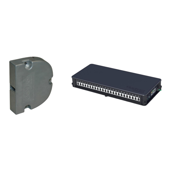
GAT SMART.Lock 7000 System General Information GENERAL INFORMATION System Parts The GAT SMART.Lock 7000 system consists of the following system parts: 3. GAT SMART.Controller S 7000 (Slave Controller) 2. GAT SMART.Lock 7000 Bolt Set (Bolt Set) 1. GAT SMART.Lock 7001 4. -
Page 10: Ordering Guide
13. COM Converter Different COM Converters are available to convert RS 485 to Ethernet. Ordering Guide For the planning and ordering of the GAT SMART.Lock 7000 system components, an ordering guide is available in a separate document (“DK_GAT-SMARTLOCK7000_Bestellhilfe-EN "). www.gantner.com... - Page 11 GAT SMART.Lock 7000 System General Information www.gantner.com HB_GAT-SMARTLOCK7000--EN_10...
-
Page 12: Gat Smart.lockaxx 6350 Central Reader
GAT SMART.Lock 7000 System General Information GAT SMART.LockAxx 6350 Central Reader Display LED traffic light display (red/green) Confirmation button Illuminated, round scan field (to read the RFID data carriers) Screw terminals for cable connection Figure 2.2 – Central reader GAT SMART.LockAxx 6350 The GAT SMART.LockAxx 6350 is a terminal designed for reading electronic RFID (Radio Frequency Identification) -
Page 13: Basic Function Of The Gat Smart.lock 7001 System
An electronic device (terminal) where users can identify themselves with their RFID data carriers in order to unlock their lockers. GANTNER Electronic GmbH offers the GAT SMART.LockAxx 6350 for this function. When a user’s data carrier has been identified as valid, the central reader sends a command to the corresponding slave controller to unlock the user’s locker. - Page 14 GAT SMART.Lock 7000 System General Information User: A person who wants to use a locker that is equipped with a GAT SMART.Lock 7001. Data Carrier: Data carriers can be used by users for identification in order to unlock their lockers. This can be done, for example, at a central reader.
-
Page 15: Installation
GAT SMART.Lock 7000 System Mounting and Installation INSTALLATION These installation instructions describe how to install the GAT SMART.Lock 7001 locker locks. Please read and follow these instructions carefully prior to working on the lockers or installing the locks. As there are a wide variety of applications and locker types, a test installation that includes functional test- ing must always be performed prior to the serial production of the lockers and the installation of the locks. - Page 16 GAT SMART.Lock 7000 System Mounting and Installation SMART 1. GAT .Lock 7001 2. Fastening screws (3x) depending on the locker material 3. Door shackle 4. Door plate 5. Distance plate 6. Connection cable 7. Connection plug 8. Mounting safety / emergency opening Figure 3.2 - Mounting overview GAT SMART.Lock 7001 for right-hinged locker doors...
-
Page 17: Measurement Diagrams For The Installation
GAT SMART.Lock 7000 System Mounting and Installation Measurement Diagrams for the Installation In this section you will find the measurement information for the hardware parts in the GAT SMART.Lock 7000 sys- tem (lock, door shackle, etc.), and other important dimensions that must be considered during installation. -
Page 18: Gat Smart.lock 7001 Housing
GAT SMART.Lock 7000 System Mounting and Installation 3.2.2 GAT SMART.Lock 7001 Housing For the length and diameter of the screws required for installation, observe the length and diameter of the mounting holes shown in Figure 3.4. Figure 3.4 - GAT SMART.Lock 7001 3.2.3 Door Shackle and Mounting Plate... -
Page 19: Important Measurements For The Installation
GAT SMART.Lock 7000 System Mounting and Installation 3.2.4 Important Measurements for the Installation Please pay close attention to the following measurements: Figure 3.8 – Important measurements for the installation : The centre of the door shackle must be 1 mm higher than the centre of the door shackle opening of the GAT SMART.Lock 7001. -
Page 20: Mounting The Gat Smart.lock 7001 On The Inner Side Of The Locker
GAT SMART.Lock 7000 System Mounting and Installation Mounting the GAT SMART.Lock 7001 on the Inner Side of the Locker Observe the following instructions to mount the GAT SMART.Lock 7001 on the inner side of the locker door. Drill the fastening holes according to the measurement diagram (Figure 3.4). -
Page 21: Mounting The Door Shackle
GAT SMART.Lock 7000 System Mounting and Installation Mounting the Door Shackle The door shackle is mounted on the inner side of the door using a door plate and a distance plate. Mount the bolt according to the following procedure: ... - Page 22 GAT SMART.Lock 7000 System Mounting and Installation Figure 3.13 - Mounting with a door plate Select suitable screws according to the type and thickness of the door. In assembled state, the door bolt must guarantee a tensile force of 2000 N.
-
Page 23: Mounting Security Bolt / Emergency Opening
GAT SMART.Lock 7000 System Mounting and Installation Mounting Security Bolt / Emergency Opening The GAT SMART.Lock 7001 is secured against unintentional locking prior to normal operation by a mounting secu- rity bolt (8). The mounting security bolt must only be removed once the mounting, electrical connection, and the functional testing of the GAT SMART.Lock 7001 have been completed successfully. -
Page 24: Test Installation
GAT SMART.Lock 7000 System Mounting and Installation Test Installation As the GAT SMART.Lock 7001 is suitable for a wide range of installation applications, always complete a test instal- lation with functional testing of a locker from the facility before starting serial production of all the lockers. In particu- lar, confirm through testing that the door shackle slides centrally into the opening of the GAT SMART.Lock 7001... -
Page 25: Electrical Connection
GAT SMART.Lock 7000 System Electrical Connection ELECTRICAL CONNECTION This chapter describes the electrical connections of the GAT SMART.Lock 7001. It also includes a description of the connection and networking of the GAT SMART.Controller S 7000. Attention: Cable connection must only be done in a powerless state and only by trained, specialised per- sonnel. -
Page 26: Cable Connection Of The Gat Smart.lock 7001
GAT SMART.Lock 7000 System Electrical Connection Cable Connection of the GAT SMART.Lock 7001 A 4m long connection cable (GAT NET.Lock Cable 4m, Part No. 321826) is supplied with the lock. This cable is used to connect the GAT SMART.Lock 7001 to a GAT SMART.Controller S 7000 control unit. The cable comes with a 4-pin MOLEX connector of the Micro-Fit 3.0... -
Page 27: Connection Of The Gat Smart.controller S 7000
The locker locks are connected via the 4-pin MOLEX connectors to the sockets of the GAT SMART.Controller S 7000 slave controller. Attention: Always use original GANTNER cables. The connection cable of the lock must not be modified (shortened or extended). If the cable is too short, only one GANTNER extension cable GAT NET.Lock Cable 4m (article #: 321826, length = 4 m) may be used. - Page 28 GAT SMART.Lock 7000 System Electrical Connection Observe the following values for the number of connectable controllers per interface: - A maximum of 8 slave controllers per RS 485 line - Maximum length of one RS 485 line = 200 m Figure 4.5 - Maximum RS 485 line length...
-
Page 29: Power Supply
GAT SMART.Lock 7000 System Electrical Connection 4.3.3 Power Supply The GAT SMART.Controller S 7000 is connected via an external power supply unit (GAT NET.Power Supply 100- 240V, see “7. Technical Data”) to a mains power supply outlet. The power supply is connected to the MOLEX plug on the side of the controller. - Page 30 GAT SMART.Lock 7000 System Electrical Connection Attention: The maximum cable length, when the power supply is transmitted from a master or slave controller to subsequent controllers, is 200 metres. Figure 4.9 – Examples of power supply If a GAT NET.Controller M 7000 master controller or a GAT SMART.LockAxx 6350 central reader is not used in the system, every GAT SMART.Controller S 7000 slave controller must be directly connected to...
-
Page 31: Signalling
GAT SMART.Lock 7000 System Electrical Connection 4.3.4 Signalling To display its operating state, various LED indicators are provided on the GAT SMART.Controller S 7000. Yellow LED Green LED Figure 4.10 - LEDs and buttons provided on the GAT SMART.Controller S 7000... -
Page 32: Connection Of The Gat Net.controller M 7000 Master Controller
GAT SMART.Lock 7000 System Electrical Connection Connection of the GAT NET.Controller M 7000 Master Controller 4.4.1 Connection of the GAT SMART.Controller S 7000 slave controller to the Master Controller The slave controllers are connected to the master controllers via RS 485 using RJ 45 plugs. The connection must be made through the "RS 485 SLAVES"... -
Page 33: Connection Of The Power Supply
GAT SMART.Lock 7000 System Electrical Connection 4.4.3 Connection of the Power Supply The GAT NET.Controller M 7000 is connected via an external power supply unit (GAT NET.Power Supply 100- 240V, see “7. Technical Data”) to a mains power supply outlet. The power supply is connected to the MOLEX plug on the side of the controller. -
Page 34: Connection Of The "Moxa N-Port" Com Converter
485 interface to Ethernet, thereby enabling the connection of the slave controllers to, for example, a higher-level host computer (PC/server). The connectivity and functionality of the MOXA COM Convertor varies by type. GANTNER offers the following MOXA COM Converters: - COM Converter Moxa 1-port EU (GANTNER Art.Nr.: 647787): One serial port (DB-9), EU power plug - COM Converter Moxa 1-port UK (GANTNER Art.Nr.: 873182):... -
Page 35: Connection Of The Gat Smart.controller S 7000 Slave Controller And Ethernet
GAT SMART.Lock 7000 System Electrical Connection 4.6.1 Connection of the GAT SMART.Controller S 7000 Slave Controller and Ethernet The slave controllers are connected to the GAT SMART.LockAxx 6350 via RS 485 using screw terminals. The con- nection must be realised at the RS 485 socket. - Page 36 GAT SMART.Lock 7000 System Electrical Connection www.gantner.com HB_GAT-SMARTLOCK7000--EN_10...
-
Page 37: Configuration
GAT SMART.Lock 7000 System Configuration CONFIGURATION Configuration of the GAT SMART.LockAxx 6350 Central Reader Functionality settings are settings referring to the functions that the GAT SMART.LockAxx 6350 offers and define how the device interacts with the users. These settings can be viewed and edited with the "GAT Configuration Man- ager"... - Page 38 GAT SMART.Lock 7000 System Configuration In the left section (1) the configuration categories are shown. After selecting a category, the right section (2) dis- plays the configuration options of the selected category. In order to manage the configuration of one or more central readers in a project, follow these steps: Figure 5.3 - Open the project...
-
Page 39: Configuration Parameters And The Corresponding Default Settings
GAT SMART.Lock 7000 System Configuration Select the central reader to be configured from the device list on the left. Use the "Add Location" and "Add Device" buttons to add another central reader to this list. After selecting a central reader the device settings are shown in the right section. - Page 40 GAT SMART.Lock 7000 System Configuration Open All Clear … All lockers are opened and all “Free Locker” allocations are deleted Controller 1 Locker Numbers e.g.: Configuration string for the channel number / RegExp locker number assignment of controller 1 c1=10;c2=11;...
- Page 41 GAT SMART.Lock 7000 System Configuration Rentallocker Auto save offline data Defines if the device will store the authoriza- Boolean True tion data of the data carriers that has been transferred with the "Card ID" command Multiple lock handling Defines the action to take when a user has multiple lockers assigned: Open all ...
-
Page 42: Configuration Of The Moxa Com Converter
GAT SMART.Lock 7000 System Configuration Configuration of the MOXA COM Converter The MOXA COM Converters are configured via the Ethernet interface. The configuration can be done either via the NPort 5100 Administrator Suite software or via a web interface (using a web browser). The IP address of the MOXA COM Converter can also be set using ARP Commands. - Page 43 GAT SMART.Lock 7000 System Configuration Figure 5.6 - COM Converter MOXA - Network configuration example Click on the "Serial" tab and set these parameters to the serial interface of the MOXA COM Converter at which the slave controllers are connected. Enter the values as shown below ("Port alias" can be freely defined).
- Page 44 GAT SMART.Lock 7000 System Configuration If multiple serial ports on the MOXA COM Converter are available, you can configure all ports here. Switch to the "Operating Mode" tab and select the "Modify" box. Select the TCP Server Mode and click on "Settings".
- Page 45 GAT SMART.Lock 7000 System Configuration Figure 5.9 - COM Converter MOXA - Server COM Port Settings Configure the following parameters on the “Advanced Settings” tab. Figure 5.10 - COM Converter MOXA – Advanced Settings for Server Connection Configure the following parameters on the “Serial Parameters” tab.
- Page 46 GAT SMART.Lock 7000 System Configuration Figure 5.11 - COM Converter MOXA – Serial Settings Confirm the settings with “OK”. Now the GAT SMART.Lock 7001 and slave controller system is ready to be managed by a server running cor- responding software (e.g., GAT Relaxx), provided all system hardware has been properly installed and put into...
-
Page 47: Operation
Note: For future applications, GANTNER plans to include this procedure in PC software. The option will be inte- grated into future versions of GAT Relaxx, the locker system management software from GANTNER. GAT Relaxx includes an integrated help manual that describes all software functions in detail. -
Page 48: Gat Relaxx - Operating Software For Gat Smart.lock 7001
GAT Relaxx – Operating Software for GAT SMART.Lock 7001 In order to configure, operate and monitor the locker system, GANTNER Electronic GmbH offers the PC software GAT Relaxx. The slave controllers and the connected locks are graphically displayed to show their status. The communication to the GAT SMART.Controller S 7000 in the system runs on Windows "GAT Relaxx". - Page 49 GAT SMART.Lock 7000 System Operation Hardware View Figure 6.1 - GAT Relaxx – Hardware View The hardware view is divided into the following areas: - Main menu: Access to all GAT Relaxx functions by selecting the corresponding menu points. - Symbol bar: Fast access to the main functions.
- Page 50 GAT SMART.Lock 7000 System Operation Organization View Figure 6.2 - GAT Relaxx - Organization View The areas (5), (6), (7) and (8) serve a different purpose in the “Organization View” interface: - System overview: Here, the lockers of a system are logically divided into "areas" (e.g., male locker room, female locker room).
-
Page 51: Technical Data
GAT SMART.Lock 7000 System Technical Data TECHNICAL DATA GAT SMART.Lock 7001 Nominal voltage U 24 V Permitted input voltage U 19.2 to 28.8 V (±20%) Current consumption of the coil: 1 A @ 24 V (500 ms) Perm. switching current (contact): 1 mA Std. -
Page 52: Gat Smart.controller S 7000
GAT SMART.Lock 7000 System Technical Data - Master to slave (RS 485): RJ 45 - Power supply: MOLEX Housing material: Plastic (ABS) Dimensions: 310 x 133 x 42 mm Permitted ambient temperature: 0 to +60 °C Protection type: IP 40... - Page 54 GANTNER Electronic GmbH GANTNER Electronic GmbH Deutschland GANTNER Electronics PTY LTD Australia Montafonerstraße 8 Industriestraße 40F Unit 6 15/17 Chaplin Drive, West Lane Cove 6780 Schruns, Austria 44894 Bochum, Germany Sydney NSW 2006, Australia T +43 5556 73784-0 T +49 234 58896-0...
Need help?
Do you have a question about the GAT SMART.Lock 7000 System and is the answer not in the manual?
Questions and answers