Table of Contents
Advertisement
Quick Links
It is of vital importance, before attempting to operate your engine,
to read the general 'SAFETY INSTRUCTIONS AND WARNINGS'
section on pages 2-4 of this booklet and to strictly adhere to the
advice contained therein.
•
Also, please study the entire contents of this instruction manual,
so as to familiarize yourself with the controls and other features
of the engine.
•
Keep these instructions in a safe place so that you may readily
refer to them whenever necessary.
•
It is suggested that any instructions supplied with the aircraft,
radio control equipment, etc., are accessible for checking at the
same time.
Advertisement
Table of Contents

Subscribe to Our Youtube Channel
Related Manuals for O.S. engine MAX 140RX FI


Summary of Contents for O.S. engine MAX 140RX FI
- Page 1 It is of vital importance, before attempting to operate your engine, to read the general 'SAFETY INSTRUCTIONS AND WARNINGS' section on pages 2-4 of this booklet and to strictly adhere to the advice contained therein. • Also, please study the entire contents of this instruction manual, so as to familiarize yourself with the controls and other features of the engine.
-
Page 2: Table Of Contents
CONTENTS SAFETY INSTRUCTIONS AND WARNINGS ABOUT YOUR O.S. ENGINE INTRODUCTION, FEATURES BASIC ENGINE PARTS CONNECTING WITH THE EC-1 EC-1 DISPLAYS AND EXPLANATIONS LIST OF 140RX-FI USAGE CONDITIONS INSTALLATION PROCEDURE 10-11 11-13 LINKAGE AND INITIAL SETTINGS ENGINE STARTING AND AIR-FUEL MIXTURE ADJUSTMENT... -
Page 3: Safety Instructions And Warnings About Your O.s. Engine
If at some future date, your O.S. engine is acquired by another person, we would respectfully request that these instructions are also passed on to its new owner. - Page 4 NOTES • This engine was designed for model aircraft. Do not attempt to use it for any other purpose. • Mount the engine in your model securely, following the manufacturers' recommendations, using appropriate screws and locknuts. • Be sure to use the silencer (muffler) supplied with the engine. Frequent exposure to an open exhaust may eventually impair your hearing.
- Page 5 NOTES • Adjust the throttle linkage so that the engine stops when the throttle stick and trim lever on the transmitter are fully retarded. Alternatively, the engine may be stopped by cutting off the fuel supply. Never try to stop the engine physically.
-
Page 6: Introduction, Features
INTRODUCTION This engine is the MAX-140RX-FI (fuel injection) engine equipped with a revolutionary fuel supply system that was jointly developed by Futaba, a manufacturer of Radio control equipment, and Ogawa Seiki, a manufacturer of model engines. This system detects engine speed with a sensor based on throttle signals transmitted from a transmitter. -
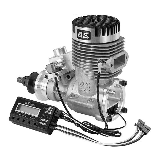
Page 7: Basic Engine Parts
BASIC ENGINE PARTS Glow plug TYPE F Cylinder Head Accessories •Fuel Filter Injector Air Valve 70C •Check Valve Crankshaft Injector •Y harness Temperature Sensor •Driver to push EC-1 keys •Duble-sided sponge-backed Drive Hub cushioning tape Pressure Fitting Crankshaft Fuel Filter Cover Plate Check Valve RPM Sensor... -
Page 8: Connecting With The
CONNECTING WITH THE EC-1 Connect the receiver and servo-related components (rudder section) in the same manner as in the past. (5) Rotation sensor input terminal (r.p.m.) (4) Temperature sensor input terminal (Temp) (3) Injector output terminal (INJECTOR) (2) Injection trim input terminal (AUX TRIM) (1) Injection time input terminal (CH3:THRO) -
Page 9: Displays And Explanations
EC-1 DISPLAYS AND EXPLANATIONS When the power supplies of the transmitter and receiver are turned on and function key pressed with a pressing rod (non-metallic rod), the LCD display changes in the manner shown below. (The display changes in the opposite order when function key is pressed.) Power ON The current engine speed is displayed. - Page 10 Explanation of TmD ATL and TmD Fine TmD ATL This adjustment mechanism allows adjustment of a single trim point using the slow position as the origin. Adjustment uses the injection trim adjustment dial (spare channel dial) on the transmitter. There is no change at Lo (slow position) while the trim volume reaches a maximum at Hi.
-
Page 11: List Of 140Rx-Fi Usage Conditions
List of 140RX-FI Usage Conditions Part Manufacturer Name Remarks Exhaust manifold O.S. *For the 140RX Tuned silencer O.S. *T-6010 Glow plug O.S. *Type F Commercially Propeller General references: Mid-range engine speed available should be approximately *16x14(2 blades) high-quality 6,500 rpm. product Maximun speed should be 15x12(4 blades) -
Page 12: Linkage And Initial Settings
(3) Fuel Tank and Lines Fig.3 Fuel filter (provided) T nipples (sold separately) Check valve (provided) Tank pressure ven line Fuel supply line Connect all lines securely as shown in the figure above. Since high pressure is applied to the fuel tank from the engine crankcase, make connections using a commercially available, thick-walled silicon tube. - Page 13 Call up the ATV menu on the condition Rotor mark menu and select THR. Center mark Confirm that it is in the center of the throttle curve when the stick is in the center position. 55˚ Then align the mark in the center of the air valve at that point.
-
Page 14: Engine Starting And Air-Fuel Mixture Adjustment
(4) Adjustment of Amount of Throttle Servo and Air Valve Angle Move the throttle stick on the transmitter to slow and then full high. If there is excessive or insufficient opening of the air valve, adjust the opening with the throttle angle adjustment function (ATV). -
Page 15: Engine Starting
Engine Starting (1) Always be sure to close the throttle stick to idle position before applying the starter and starting battery. (Do not attempt to start the engine manually since this is potentially dangerous.) After the engine has started, gradually move the throttle stick on the transmitter to the full high position. -
Page 16: Flight Adjustment
Case of a 15 x 13.5, General reference Case of a 16 x 14, 3-blade propeller for engine speed 2-blade propeller 1,700 1,800r.p.m. 1,700 1,800r.p.m. Full slow engine speed Intermediate slow 6,400 7,000r.p.m. 6,400 6,600r.p.m. engine speed Full high engine speed 7,300 7,900r.p.m. -
Page 17: Glow Plug
If the engine produces a higher pitch sound immediately after taking off or if the engine appears to lose power and exhaust cannot be seen at all (although varying somewhat depending on the fuel), turn the injection trim adjustment dial (spare channel dial) in the (+) rich direction by about 45˚ with the throttle stick in the full high position and reconfirm engine operation by continuing to fly for 3-4 minutes. -
Page 18: Care & Maintenance
Care After Use • First vent the pressure from the fuel tank. Next, drain any fuel in the fuel tank. Turn on the transmitter and receiver switches but do not heat the plug. Move the transmitter engine control lever to the center position without heating the plug, and then turn the engine over with the electric starter several times. -
Page 19: Troubleshooting
Troubleshooting Problem Confirmation Engine does not start Is the power turned on? • • Are the connectors securely connected? Is the lead wire broken? • Is the plug burned out? • • Has Lmt been set? Is engine speed displayed on the EC-1 when the engine is running? •... -
Page 20: Three View Drawing
THREE VIEW DRAWING Dimensions(mm) Specifications 4-ø5.1 Displacement 23.0cc/1.404cu.in. Bore 32.0mm/1.260in. Stroke 28.6mm/1.126in. PracticalR.P.M. 1.800 10.000r.p.m. Output 3.5bhp/9.000r.p.m. Weight 807g/28.5oz. ø55 UNF 5/16-24 M4x0.7 48.4 O.S. GENUINE PARTS & ACCESSORIES T-6010 TUNED SILENCER EXHAUST HEADER PIPE 5/16-M5 LOCK NUT SET (72102100) (72104200) (45910300) SUPER FILTER ( L ) -
Page 21: Exploded View
ENGINE & INJECTOR AIR VALVE EXPLODED VIEW C.M3X8 C.M3.5X18 C.M2.6X8 C.M4X10 Type of screw C … Cap Screw M … Oval Fillister-Head Screw F … Flat Head Screw N … Round Head Screw S … Set Screw... -
Page 22: Parts List
ENGINE PARTS LIST Code No. Description Cylinder Head 2 9404 100 Piston Ring 2 9403 400 Piston 2 9403 200 Piston Pin 2 9406 000 Piston Pin Retainer 2 8117 000 Connecting Rod 2 9405 000 Cylinder Liner 2 9403 100 Injector Air Valve Set (70c) 2 9483 010 Gasket... - Page 23 MEMO...
- Page 24 6-15 3-Chome Imagawa Higashisumiyoshi-ku Osaka 546-0003, Japan TEL. (06) 6702-0225 FAX. (06) 6704-2722 http://www.os-engines.co.jp Copyright 2000 by O.S.Engines Mfg. Co., Ltd. All rights reserved. Printed in Japan. 080101...
Need help?
Do you have a question about the MAX 140RX FI and is the answer not in the manual?
Questions and answers