
Related Manuals for National Instruments NI 9237E Series


Summary of Contents for National Instruments NI 9237E Series
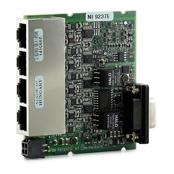
- Page 1 OPERATING INSTRUCTIONS AND SPECIFICATIONS NI 9237E 4-Channel, 24-Bit Half/Full-Bridge Analog Input Module...
- Page 2 This document describes how to use the National Instruments 9237E and includes dimensions, pin assignments, and specifications for the NI 9237E. In this document, the NI 9237E with RJ-50 connectors and the NI 9237E with DSUB are referred to inclusively as the NI 9237E.
- Page 3 NI 9237E Dimensions The following figure shows the dimensions of the NI 9237E. 73.4 (2.89) 0.0 (0.00) Figure 1. NI 9237E Dimensions in Millimeters (Inches) © National Instruments Corp. NI 9237E Operating Instructions and Specifications...
- Page 4 Connecting the NI 9237E The NI 9237E has four RJ-50 receptacles or a 37-pin DSUB connector that provides connections for four half or full bridges, and an external excitation voltage source. Ch0 – Ch3 AI– Ch 0 RS– EX– Ch 1 T–...
- Page 5 Figure 3. NI 9237E with DSUB Pin Assignments © National Instruments Corp. NI 9237E Operating Instructions and Specifications...
- Page 6 NI 9944 and NI 9945 Quarter Bridge Completion Accessories for more information about these accessories and how to purchase them. National Instruments does not recommend using Note an RJ-45 cable with the NI 9237E with RJ-50 because it...
- Page 7 National Instruments recommends performing bridge calibrations of quarter- or half-bridge sensors after connecting all sensors to the NI 9237E and after removing or attaching any additional sensor.
- Page 8 AI– EX– RS– /SC– RS– TEDS T– NI 9237E NI 9237E with DSUB only NI 9237E with RJ-50 only Figure 4. Connecting a Half or Full Bridge to the NI 9237E NI 9237E Operating Instructions and Specifications ni.com...
- Page 9 (CMRR). You also can connect floating signals to the NI 9237E. If you connect floating signals to the NI 9237E, National Instruments recommends connecting the EX– signal to the earth ground or shield for better noise rejection.
- Page 10 Wiring TEDS Channels Ensure that neither the TEDS data (T+) nor the TEDS return (T–) signal is tied in common to any AI signals on the NI 9237E. The NI 9237E connects all the T– signals together internally. The NI 9237E with DSUB has only three T– pins. To connect four TEDS sensors to the NI 9237E with DSUB, wire the TEDS return signals of two of the sensors to one of the T–...
- Page 11 NI 9237E. R lead R bridge R bridge AI– R bridge R bridge EX– R lead RS– NI 9237E Figure 5. Connecting Remote Sense Wires to the NI 9237E © National Instruments Corp. 11 NI 9237E Operating Instructions and Specifications...
- Page 12 The actual bridge excitation voltage is smaller than the voltage at the EX+ and EX– leads. If you do not use remote sensing of the actual bridge voltage, the resulting gain error is: lead ----------------- for half-bridge sensors and bridge ...
- Page 13 The difference in these two measurements provides an indication of the gain errors from wiring resistances. You can design the software application to correct subsequent readings for this gain error. © National Instruments Corp. 13 NI 9237E Operating Instructions and Specifications...
- Page 14 2.5 V, 3.3 V, 5 V, or 10 V of excitation voltage, and the module can provide up to 150 mW of excitation power. Unless you supply external excitation voltage, National Instruments recommends that you set the excitation voltage to a value that keeps the total power below 150 mW.
- Page 15 You can use the additional EX+ and EX– terminals on the connector to wire multiple NI 9237E modules together in a daisy chain. © National Instruments Corp. 15 NI 9237E Operating Instructions and Specifications...
- Page 16 Understanding NI 9237E Filtering The NI 9237E uses a combination of analog and digital filtering to provide an accurate representation of in-band signals while rejecting out-of-band signals. The filters discriminate between signals based on the frequency range, or bandwidth, of the signal. The three important bandwidths to consider are the passband, the stopband, and the alias-free bandwidth.
- Page 17 0.025 0.000 –0.025 –0.050 Frequency/Data Rate Figure 6. Typical Passband Flatness for the NI 9237E © National Instruments Corp. 17 NI 9237E Operating Instructions and Specifications...
-
Page 18: Alias-Free Bandwidth
Stopband The filter significantly attenuates all signals above the stopband frequency. The primary goal of the filter is to prevent aliasing. Therefore, the stopband frequency scales precisely with the data rate. The stopband rejection is the minimum amount of attenuation applied by the filter to all signals with frequencies within the stopband. - Page 19 12.8 MHz, the NI 9237E has a different set of data rates. The NI cRIO-9151 R Series Expansion chassis Note does not support sharing timebases between modules. © National Instruments Corp. 19 NI 9237E Operating Instructions and Specifications...
-
Page 20: Sleep Mode
Sleep Mode This module supports a low-power sleep mode. Support for sleep mode at the system level depends on the chassis that the module is plugged into. Refer to the chassis manual for information about support for sleep mode. If the chassis supports sleep mode, refer to the software help for information about enabling sleep mode. -
Page 21: Specifications
Internal master timebase (f Frequency ........12.8 MHz Accuracy........±100 ppm max Data rate range (f ) using internal master timebase Minimum ........1.613 kS/s Maximum ........50 kS/s © National Instruments Corp. 21 NI 9237E Operating Instructions and Specifications... - Page 22 Data rate range (f ) using external master timebase Minimum ........391 S/s Maximum ........51.36 kS/s -------------------- - Data rates )........, n = 1, 2, …, 31 Typical input range ......±25 mV/V Scaling coefficient ......2.9802 nV/V per LSB Overvoltage protection between any two pins......
- Page 23 2.5 V excitation ......0.6 V/V per °C 3.3 V excitation ......0.5 V/V per °C 5 V excitation ......0.3 V/V per °C 10 V excitation ......0.2 V/V per °C © National Instruments Corp. 23 NI 9237E Operating Instructions and Specifications...
- Page 24 Half-bridge completion Tolerance ........±1200 V/V max Drift ..........1.5 V/V per °C Channel-to-channel matching (calibrated) Input Signal Gain Phase Frequency Typical Maximum Maximum · 0 to 1 kHz 0.15% 0.3% 0.125°/kHz 1 to 20 kHz 0.4% 1.1% Phase nonlinearity = 0 to 1 kHz...
- Page 25 = 10 kS/s........60 dB @ 640 kHz = 50 kS/s........90 dB @ 3.2 MHz Common-mode voltage, all signals to earth ground....±60 VDC Rejection by analog prefilter of signal frequencies at oversample rate. © National Instruments Corp. 25 NI 9237E Operating Instructions and Specifications...
- Page 26 CMRR Relative to earth ground = 0 to 60 Hz) ......140 dB Relative to EX– = 0 to 1 kHz) ......85 dB SFDR (1 kHz, –60 dBFS)....115 dB Total Harmonic Distortion (THD) 1 kHz, –20 dBFS ......–95 dB 8 kHz, –20 dBFS ......
- Page 27 Bridge Bridge Bridge 2.5 V 3.3 V 10 V Excitation noise ........ 100 V Crosstalk (not including cable effects) = 1 kHz........110 dB = 10 kHz......... 100 dB © National Instruments Corp. 27 NI 9237E Operating Instructions and Specifications...
- Page 28 Excitation Internal voltage......2.5 V, 3.3 V, 5.0 V, 10.0 V Internal power......150 mW max External voltage......2 V to 10 V Shunt calibration Resistance........100 k Resistor accuracy 25 °C ........±110 –40 to 85 °C......±200 MTBF NI 9237E with RJ-50....
-
Page 29: Power Requirements
For two-dimensional drawings and Note three-dimensional models of the C Series module and connectors, visit and search by ni.com/dimensions module number. © National Instruments Corp. 29 NI 9237E Operating Instructions and Specifications... - Page 30 Weight NI 9237E with RJ-50....53 g (1.9 oz) NI 9237E with DSUB ....49 g (1.7 oz) Safety Safety Voltages Connect only voltages that are within the following limits. Between any two pins ....... ±30 V max Isolation Channel-to-channel ....None Channel-to-earth ground Continuous ......
- Page 31 • IEC 61010-1, EN 61010-1 • UL 61010-1, CSA 61010-1 For UL and other safety certifications, refer to the Note product label or the Online Product Certification section. © National Instruments Corp. 31 NI 9237E Operating Instructions and Specifications...
-
Page 32: Online Product Certification
Certification column. Environmental National Instruments C Series modules are intended for indoor use only but may be used outdoors if installed in a suitable enclosure. Refer to the manual for the chassis you are using for more information about meeting these specifications. -
Page 33: Environmental Management
Maximum altitude......2,000 m Pollution Degree ....... 2 Environmental Management National Instruments is committed to designing and manufacturing products in an environmentally responsible manner. NI recognizes that eliminating certain hazardous substances from our products is beneficial to the environment and to NI customers. - Page 34 National Instruments (RoHS) National Instruments RoHS (For information ni.com/environment/rohs_china about China RoHS compliance, go to ni.com/ environment/rohs_china Calibration You can obtain the calibration certificate and information about calibration services for the NI 9237E at ni.com/calibration. Calibration interval ......1 year NI 9237E Operating Instructions and Specifications 34 ni.com...
-
Page 35: Where To Go For Support
Where to Go for Support The National Instruments Web site is your complete resource for technical support. At you have access to ni.com/support everything from troubleshooting and application development self-help resources to email and phone assistance from NI Application Engineers. - Page 36 Turkey 90 212 279 3031, United Kingdom 44 (0) 1635 523545 National Instruments, NI, ni.com, and LabVIEW are trademarks of National Instruments Corporation. Refer to the Terms of Use section on ni.com/legal for more information about National Instruments trademarks. Other product and company names mentioned herein are trademarks or trade names of their respective companies.
Need help?
Do you have a question about the NI 9237E Series and is the answer not in the manual?
Questions and answers