
Related Manuals for National Instruments NI 9234E


Summary of Contents for National Instruments NI 9234E
- Page 1 OPERATING INSTRUCTIONS AND SPECIFICATIONS NI 9234E 4-Channel, ±5 V, 24-Bit Software-Selectable IEPE and AC/DC Analog Input Module...
- Page 2 The NI 9234E must be installed inside a suitable Caution enclosure prior to use. Hazardous voltages may be present. Do not operate the NI 9234E in a manner not Caution specified in these operating instructions. Product misuse can result in a hazard. You can compromise the safety protection built into the product if the product is damaged in any way.
- Page 3 NI 9234E Dimensions The following figure shows the dimensions of the NI 9234E. Figure 1. NI 9234E Dimensions in Millimeters (Inches) 4x Ø 3.18 (0.125) 73.38 (2.889) 7.33 (0.289) 0.00 (0.000) NI 9234E Operating Instructions and Specifications| © National Instruments | 3...
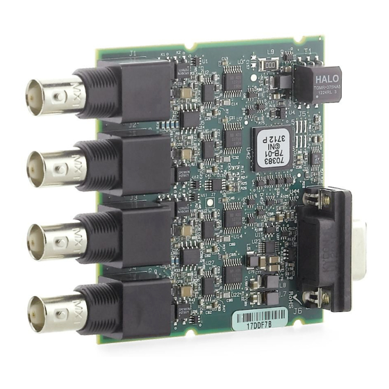
- Page 4 Connecting the NI 9234E The NI 9234E has four BNC connectors that provide connections to four simultaneously sampled analog input channels. NI 9234E Connector Assignments Figure 2. AI0+ AI0– AI1+ AI1– AI2+ AI2– AI3+ AI3– 4 | ni.com | NI 9234E Operating Instructions and Specifications...
- Page 5 If you make a ground-referenced connection between the signal source and the NI 9234E, make sure the voltage on the AI- shell is in the common-mode range to ensure proper operation of the NI 9234E. The AI- shell is protected against accidental contact with overvoltages within the overvoltage protection range.
- Page 6 Refer to Figures 3 and 4 for illustrations of connecting grounded and floating signal sources to the NI 9234E. Connecting a Grounded Signal Source to the NI 9234E Figure 3. Signal Source – NI 9234E Common AI– Mode Voltage 6 | ni.com | NI 9234E Operating Instructions and Specifications...
- Page 7 – NI 9234E AI– The NI 9234E can also provide an IEPE excitation current for each channel to measure ground-referenced or floating IEPE sensors. Typical IEPE sensors have a case that is electrically isolated from the IEPE electronics, so connecting the sensor to the NI 9234E results in a floating connection even though the case of the sensor is grounded.
- Page 8 NI 9234E Circuitry The NI 9234E analog input channels are referenced to chassis ground through a 50 Ω resistor. To minimize ground noise, make sure the chassis ground is connected to earth ground. Each channel is protected from overvoltages. The input signal on each channel is buffered, conditioned, and then sampled by a 24-bit Delta-Sigma ADC.
- Page 9 The NI 9234E uses common-mode bias current to bias the current-limiting diodes when IEPE current is turned off. When the NI 9234E is using grounded signal sources, this current causes an error that is dependent on the AI- lead impedance. This error is approximately 50 ppm of range and 15 ppm of reading per Ω...
- Page 10 Understanding NI 9234E Filtering The NI 9234E uses a combination of analog and digital filtering to provide an accurate representation of in-band signals while rejecting out-of-band signals. The filters discriminate between signals based on the frequency range, or bandwidth, of the signal.
- Page 11 The small amount of variation in gain with respect to frequency is called the passband flatness. The digital filters of the NI 9234E adjust the frequency range of the passband to match the data rate. Therefore, the amount of gain or attenuation at a given frequency depends on the data rate.
- Page 12 Stopband The filter significantly attenuates all signals above the stopband frequency. The primary goal of the filter is to prevent aliasing. Therefore, the stopband frequency scales precisely with the data 12 | ni.com | NI 9234E Operating Instructions and Specifications...
-
Page 13: Alias-Free Bandwidth
Alias-Free Bandwidth Any signal that appears in the alias-free bandwidth of the NI 9234E is not an aliased artifact of signals at a higher frequency. The alias-free bandwidth is defined by the ability of the filter to reject frequencies above the stopband frequency, and it is equal to the data rate minus the stopband frequency. - Page 14 17.067 kS/s, and so on down to 1.652 kS/s, depending on the value of n. When using an external timebase with a frequency other than 13.1072 MHz, the NI 9234E has a different set of data rates. The cRIO-9151 R Series Expansion chassis does Note not support sharing timebases between modules.
-
Page 15: Sleep Mode
In sleep mode, the system consumes minimal power and may dissipate less heat than it does in normal mode. Refer to the Specifications section for more information about power consumption and thermal dissipation. NI 9234E Operating Instructions and Specifications| © National Instruments | 15... -
Page 16: Specifications
Type of TEDS supported ....IEEE 1451.4 TEDS Class I Internal master timebase (f Frequency ........13.1072 MHz Accuracy........±50 ppm max Data rate range (f ) using internal master timebase Minimum........1.652 kS/s Maximum ........51.2 kS/s 16 | ni.com | NI 9234E Operating Instructions and Specifications... - Page 17 -3 dB........... 0.5 Hz -0.1 dB........4.6 Hz max The data rate must remain within the appropriate data rate range. Refer to the Understanding NI 9234E Data Rates section for more information. NI 9234E Operating Instructions and Specifications| © National Instruments | 17...
- Page 18 AC cutoff frequency response –0.5 –1.0 Frequency (Hz) Input range ........±5 V 18 | ni.com | NI 9234E Operating Instructions and Specifications...
- Page 19 Common-mode voltage range (AI- to earth ground)......±2 V max IEPE excitation current (software-selectable on/off) Minimum........2.0 mA Typical ........2.1 mA Power-on glitch......... 90 μA for 10 μs NI 9234E Operating Instructions and Specifications| © National Instruments | 19...
- Page 20 For a signal source connected to AI+ and AI- ......±30 V For a low-impedance source connected to AI+ and AI-... -6 V to 30 V + 3.2 μs Input delay ........40.0/f 20 | ni.com | NI 9234E Operating Instructions and Specifications...
- Page 21 Local ambient temperature. Refer to the Environmental section for more information about operatingtemperatures. † Range = 5.1 V Refer to the NI 9234E Circuitry section for information regarding grounded signal sources and measurement accuracy. NI 9234E Operating Instructions and Specifications| © National Instruments | 21...
- Page 22 Frequency ........0.45 · f Flatness (f = 51.2 kS/s)....±40 mdB (pk-to-pk max) Phase nonlinearity = 51.2 kS/s) ........±0.45° max Stopband Frequency ........0.55 · f Rejection........100 dB 22 | ni.com | NI 9234E Operating Instructions and Specifications...
- Page 23 103 dBFS 50 μV 40 μV 25 μV Noise density 310 nV/√Hz 350 nV/√Hz 780 nV/√Hz Input impedance Differential ......... 305 kΩ AI- (shield) to chassis ground ..50 Ω NI 9234E Operating Instructions and Specifications| © National Instruments | 23...
- Page 24 MTBF ..........390,362 hours at 25 °C; Bellcore Issue 2, Method 1, Case 3, Limited Part Stress Method Contact NI for Bellcore MTBF specifications Note at other temperatures or for MIL-HDBK-217F specifications. 24 | ni.com | NI 9234E Operating Instructions and Specifications...
-
Page 25: Power Requirements
For two-dimensional drawings and Note three-dimensional models of the C Series module and connectors, visit and search by ni.com/dimensions module number. Weight..........71 g (2.5 oz) NI 9234E Operating Instructions and Specifications| © National Instruments | 25... -
Page 26: Safety Voltages
Such voltage measurements include signal levels, special equipment, limited-energy parts of equipment, circuits powered by regulated low-voltage sources, and electronics. Do not connect the NI 9234E to signals or use Caution for measurements within Measurement Categories II, III, or IV. -
Page 27: Safety Standards
To obtain product certifications and the Declaration of Conformity (DoC) for this product, visit , search by ni.com/certification model number or product line, and click the appropriate link in the Certification column. NI 9234E Operating Instructions and Specifications| © National Instruments | 27... - Page 28 Pollution Degree ....... 2 Local ambient temperature. Measure the local ambient temperature by placing thermocouples on both sides of the PCB, 5 mm (0.2 in.) from the board surface. 28 | ni.com | NI 9234E Operating Instructions and Specifications...
-
Page 29: Environmental Management
WEEE recycling center. For more information about WEEE recycling centers, National Instruments WEEE initiatives, and compliance with WEEE Directive 2002/96/EC on Waste and Electronic Equipment, visit ni.com/environment/ weee NI 9234E Operating Instructions and Specifications| © National Instruments | 29... -
Page 30: Where To Go For Support
The National Instruments Web site is your complete resource for technical support. At you have access to ni.com/support everything from troubleshooting and application development self-help resources to email and phone assistance from NI Application Engineers. 30 | ni.com | NI 9234E Operating Instructions and Specifications... - Page 31 LabVIEW, National Instruments, NI, ni.com, the National Instruments corporate logo, and the Eagle logo are trademarks of National Instruments Corporation. Refer to the Trademark Information at ni.com/trademarks for other National Instruments trademarks.
Need help?
Do you have a question about the NI 9234E and is the answer not in the manual?
Questions and answers