
Related Manuals for LS SV-iS7 Series


Summary of Contents for LS SV-iS7 Series
- Page 1 SV-iS7 Pulse Encoder Interface Option Module iS7 EtherNet/IP User Manual SV-iS7 Series User Manual...
- Page 2 iS7 Ethernet Option Manual Safety Precaution First thank you for using our iS7 Ethernet Option Board! Please follow the following safety attentions since they are intended to prevent any possible accident and danger so that you can use this product safely and correctly.
- Page 3 iS7 Ethernet Option Manual WARNING DC link voltage is discharged with a meter (below DC 30V). Otherwise, you may get an electric shock. Operate the switches with dry hands. Otherwise, you may get an electric shock. Do not use the cable when its insulating tube is damaged. Otherwise, you may get an electric shock.
- Page 4 iS7 Ethernet Option Manual Table of Contents Table of Contents ...................... 3 Introduction ......................4 Ethernet Technical Features ................4 Product Constituents ..................4 The External and Mounting of Ethernet Option Module ........5 Network Connection ..................7 Network Cable Standard ..................8 Ethernet Option and Related Keypad Parameters ..........
- Page 5 iS7 Ethernet Option Manual Introduction Ethernet communication option module connects the iS7 inverter to the Ethernet network. It supports 2 kinds of protocol, Modbus/TCP and EtherNet/IP. Controlling and monitoring of inverter can be done by PLC sequence program or any Master Module. Since Ethernet which constitutes Internet has been used and IPv4 has been supported, wherever Internet can be done, controlling and monitoring is possible.
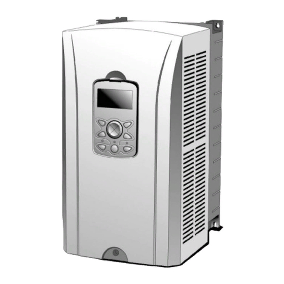
- Page 6 iS7 Ethernet Option Manual The External and Mounting of Ethernet Option Module The External of Ethernet option module LED Composition Green 2Color 2Color LED0 LED1 LED2 LED3...
- Page 7 iS7 Ethernet Option Manual (3) Mounting the communication option module on iS7 inverter ① Remove the cover of the iS7 inverter. ② iS7 communication option After connecting the EtherNET / IP communication option to the connection part, tighten the screws (2 pieces). ③...
- Page 8 iS7 Ethernet Option Manual 5. Network Connection Terminal block for communication cable Pin No. Signal Description Cable Color Transmitting data plus (+) White/Yellow Transmitting data minus (-) Yellow Receiving data plus (+) White/Green NONE Not used Blue NONE Not used White/Blue Receiving data minus (-) Green...
- Page 9 iS7 Ethernet Option Manual 6. Network Cable Standard (1) Used frequency band Category 5 is used. The frequency band is up to 100 MHz, Channel performance is up to 60MHz and Transmission speed is up to 100Mbps. (2) Cable type of twisted pair cable Classi- Details Purpose of cable...
- Page 10 iS7 Ethernet Option Manual Ethernet Option and Related Keypad Parameters The functions below are the inverter parameters which shows the information related with the Modbus TCP and EtherNet/IP. In the parameter column, the “M” stands for the parameters used for Modbus TCP, and “E” stands for the parameters used for EtherNet/IP.
- Page 11 iS7 Ethernet Option Manual Related keypad parameter with iS7 Ethernet Code Pro- Number Parameter Name Default Description value tocol Automatically set up according to COM-30 ParaStatus Num the CIP Input Instance. Sets up the inverter data address 0x0000 COM-31 Para Status-1 ~0xFFFF which will be read by the client.
- Page 12 iS7 Ethernet Option Manual The Client sets up the reference 0x0000 COM-57 Para Control-7 ~0xFFFF Inverter Data Address. The Client sets up the reference 0x0000 COM-58 Para Control-8 ~0xFFFF Inverter Data Address. Updates communication related COM-94 Comm Update keypad parameters.
- Page 13 iS7 Ethernet Option Manual Option Type (Option card information, CFG-30) Automatically indicates the type of the communication card presently installed in the iS7. When the iS7 Ethernet communication card is installed, “Ethernet” is displayed. Option Version (Option version information, COM-06) Automatically indicates the version of the communication card presently installed in the iS7.
- Page 14 iS7 Ethernet Option Manual (5) Ethernet Speed (COM-22) Ethernet speed is fixed to 0 without any setting and it is automatically set to 100Mbps. (6) CIP Input Instance(COM-23) This parameter required for EtherNet/IP protocol communication the format of the inverter state data which are sent by the inverter to the Client (Originator) during the I/O communication of CIP (Common Industrial Protocol).
- Page 15 iS7 Ethernet Option Manual Input Data The number Value Instance Size of Parameter (8) Para Status (COM-30~38) This parameter is not used in case of Modbus TCP. This parameter appears only when the set value of the Input Instance (COM-17) in the EtherNet/IP is 4 or above. COM-30 Para Status Num cannot be set up but the number of the set up parameters of the instance is shown.
- Page 16 iS7 Ethernet Option Manual Inverter Communication Address See Chapter 11. Communication Function, Inverter IS-7 Manual. Modbus/TCP Frame (1) Modbus/TCP Frame Composition MBAP Header( 7 bytes) PDU (5 bytes ~) Generally, Ethernet uses Ethernet II Frame. MODBUS Application Protocol Header (MBAP Header) MBAP Header constitution is presented below.
- Page 17 iS7 Ethernet Option Manual ① Read Holding Registers The function used to read the data in the Inverter (Server). Constitution of the frame requested from Client to Server; Requested Frame Length Value Function code 1 Bytes 0x03 Comm. address 2 Bytes 0x0000 ~ 0xFFFF The number of 1~16...
- Page 18 iS7 Ethernet Option Manual Constitution of the frame sent from Server to Master in response; Response Frame Length Value 0x03 Function code 1 Bytes 2 x The requested Comm. address 1 Bytes number of data The requested Value of the data of the The number of number of data x 2 given number from the...
- Page 19 iS7 Ethernet Option Manual ④ Write Multiple Register The function used to change from 1 to 16 of the Inverter (Server) data consecutively. Constitution of the frame requested from Client to Server; Requested Frame Length Value Function code 1bytes 0x10 Comm.
- Page 20 Server is unable to respond because it is executing SLAVE DEVICE BUSY 0x06 another process (Inverter parameter initializing, initial setting of Option, etc.) When trying to change a parameter which is prohibited WRITE PERMITION 0x20 from changing. ERROR (A unique code of LS Inverters)
- Page 21 iS7 Ethernet Option Manual EtherNet/IP (1) Basic Constitution of Protocol The EtherNet/IP is a protocol which is implemented with the CIP (Common Industrial Protocol), specified by the ODVA, using TCP and UDP. Originator: the device which is requesting connection. Also called client.
- Page 22 iS7 Ethernet Option Manual (2) Implicit Message An Implicit Message is also called an I/O Message. This is the data communicated between the Client (Originator) and Server (Target) with Input Instance and Output Instance, at preset period. Class 1 connection will be implemented. ①...
- Page 23 iS7 Ethernet Option Manual ② Input Instance This is the data of Inverter status sent from Inverter to PLC or other Client devices periodically. Instance Byte Bit 7 Bit 6 Bit 5 Bit 4 Bit 3 Bit 2 Bit 1 Bit 0 Running Faulted...
- Page 24 iS7 Ethernet Option Manual Instance Byte Bit 7 Bit 6 Bit 5 Bit 4 Bit 3 Bit 2 Bit 1 Bit 0 Status Parameter - 2 data (Low Byte) Status Parameter - 2 data (Hi Byte) Status Parameter - 3 data (Low Byte) Status Parameter - 3 data (Hi Byte) Status Parameter - 1 data (Low Byte) Status Parameter - 1 data (Hi Byte)
- Page 25 iS7 Ethernet Option Manual Instance Byte Bit 7 Bit 6 Bit 5 Bit 4 Bit 3 Bit 2 Bit 1 Bit 0 Status Parameter - 5 data (Hi Byte) Status Parameter - 6 data (Low Byte) Status Parameter - 6 data (Hi Byte) Status Parameter - 1 data (Low Byte) Status Parameter - 1 data (Hi Byte) Status Parameter - 2 data (Low Byte)
- Page 26 iS7 Ethernet Option Manual Instance Byte Bit 7 Bit 6 Bit 5 Bit 4 Bit 3 Bit 2 Bit 1 Bit 0 Status Parameter - 8 data (Low Byte) Status Parameter - 8 data (Hi Byte) Below is the description of the data for the 0,1Byte of 70,71,110,111. Related Attribute Name Description...
- Page 27 iS7 Ethernet Option Manual ③ Output Instance The reference data sent from PLC or other Client device to the Inverter periodically. Instance Byte Bit 7 Bit 6 Bit 5 Bit 4 Bit 3 Bit 2 Bit 1 Bit 0 Fault Reset Speed Reference (Low Byte) –...
- Page 28 iS7 Ethernet Option Manual Instance Byte Bit 7 Bit 6 Bit 5 Bit 4 Bit 3 Bit 2 Bit 1 Bit 0 Control Parameter - 2 data (Low Byte) Control Parameter - 2 data (Hi Byte) Control Parameter - 1 data (Low Byte) Control Parameter - 1 data (Hi Byte) Control Parameter - 2 data (Low Byte) Control Parameter - 2 data (Hi Byte)
- Page 29 iS7 Ethernet Option Manual Instance Byte Bit 7 Bit 6 Bit 5 Bit 4 Bit 3 Bit 2 Bit 1 Bit 0 Control Parameter - 3 data (Hi Byte) Control Parameter - 4 data (Low Byte) Control Parameter - 4 data (Hi Byte) Control Parameter - 5 data (Low Byte) Control Parameter - 5 data (Hi Byte) Control Parameter - 6 data (Low Byte)
- Page 30 iS7 Ethernet Option Manual Instance Byte Bit 7 Bit 6 Bit 5 Bit 4 Bit 3 Bit 2 Bit 1 Bit 0 Control Parameter - 6 data (Hi Byte) Control Parameter - 7 data (Low Byte) Control Parameter - 7 data (Hi Byte) Control Parameter - 8 data (Low Byte) Control Parameter - 8 data (Hi Byte) Below is the description of the data for the 0Byte of 20,21,100,101.
- Page 31 ① Identity Object (Class 0x01, Instance 1) Attribute Attribute Data Attribute Access Attribute Name Length Value Vendor ID Word (LS Industrial System) Device Type Word (AC Drive) (Note1) Product Code Word Revision Low Byte - Major 0x0102 Revision Word...
- Page 32 iS7 Ethernet Option Manual Meaning ‘0’ Configured (always because LSIS EtherNet/IP is not supported) Reserved 0: Unknown 2: in case of incorrect IO connection 3: in case of no IO connection has ever been made 5: Major Fault 6: IO in connection Minor Recoverable Fault (when the Inverter is in Warning status) Minor Unrecoverable Fault (N/A)
- Page 33 iS7 Ethernet Option Manual ② Motor Data Object (Class 0x28, Instance 1) Attribute Attribute Attribute Access Range Definition Name 0: Non-standard motor 1: PM DC Motor 2: FC DC Motor 3: PM Synchronous Motor 4: FC Synchronous Motor 5: Switched Reluctance Motor Motor 0~10...
- Page 34 iS7 Ethernet Option Manual Service Service Support Support Definition Code for Class for Instance 0x0E Get Attribute Single 0x10 Set Attribute Single ③ Control Supervisor Object (Class 0x29, Instance 1) Attribute Attribute Attribute Access Range Definition Name Stop Forward Get / Set Operation in normal...
- Page 35 iS7 Ethernet Option Manual Attribute Attribute Access Range Definition Name Reverse Operating in normal direction Being reset or tripped Drive Normal condition for Ready Inverter operation Drive Presently not tripped Fault Presently being tripped. Trip Reset after a trip. Drive Reset can be done only Get / Set Fault...
- Page 36 iS7 Ethernet Option Manual In the above table, Run1 stands for the Forward Run Cmd. and Run 2 stands for the Reverse Run Cmd. In other words, the Option gives an operation reference to the Inverter at the moment of change from 0(FALSE) to 1(TRUE).
- Page 37 iS7 Ethernet Option Manual Drive Fault Reset At 0 1 (FALSE TRUE), the Drive Fault Reset gives TRIP RESET reference to Inverter. Overwriting 1 (TRUE) on 1 (TRUE) does not generate RESET reference to the Inverter trip. To send RESET reference from Option to Inverter in 1 (TRUE) status, write 0 (FAULT) and then write 1(TRUE) again.
- Page 38 iS7 Ethernet Option Manual Attribute Attribute Access Range Definition Name Displays present output SpeedActual 24000 frequency in [rpm] unit. Give reference on the target frequency in [rpm] Get/Set Speed Ref unit. For this, the DRV-07 24000 Freq Ref Src must have been set up to FieldBus.
- Page 39 iS7 Ethernet Option Manual (Note3) DRV-04 Dec Time value. Service Service Support Support Definition Code for Class for Instance 0x0E Get Attribute Single 0x10 Set Attribute Single ⑤ Class 0x64 (Inverter Object) – Manufacture Profile The object to access the Keypad Parameters of the Inverter. ...
- Page 40 iS7 Ethernet Option Manual 11. Lost Command (1) Inverter Keypad Parameter Code Parameter Default Set Value Description Number Name "None" "Free-Run" If a Lost Command occurs, Lost Cmd "None" "Dec" PRT-12 sets up the Inverter action. Mode "Hold Input" (Note1) "Hold Output"...
- Page 41 iS7 Ethernet Option Manual (3) Ethernet IP Lost Command Status If there is no Implicit Message Connection (Class1 Connection) between the Originator (PLC or Client) and Target (Inverter), the Option becomes Lost Command status, and after the time set up in the PRT-13, the Inverter operates according to the settings in the PRT-12.
- Page 42 iS7 Ethernet Option Manual 12. LED Information and Troubleshooting Link Color Description Status Remarks LINK1 is connected to a network and Green Normal network operation is operating normally. LED0 LINK1 Orange Network communication fault A communication fault is detected. * EtherNet/IP is running but LINK1 is LINK1 not connected not connected to a network.
- Page 43 iS7 Ethernet Option Manual Message Color Description Status Remarks Communication between the Normal communication module and the inverter is normal. Flashing EtherNet/IP communication (LED0 and LED1 flash fault (includes station asynchronously, in 1 second collision). intervals.) Flashing A communication fault is detected between the (LED0 and LED1 flash LED2...
- Page 44 iS7 Ethernet Option Manual 제품을 사용하기 전에 먼저 저희 Ethernet 옵션보드를 사용하여 주셔서 감사합니다. 안전상의 주의사항 안전상의 주의사항은 사고나 위험을 사전에 예방하여 제품을 안전하고 올바르게 사용하기 위한 것이므로 반드시 지켜주십시오. 주의사항은 ‘경고’와 ‘주의’의 두 가지로 구분되어 있으며 ‘경고’와 ‘주의’의 의미는 다음과 같습니다.
- Page 45 iS7 Ethernet Option Manual 목 차 목 차 ......................2 소개 ........................3 Ethernet Technical features ................3 제품 구성물 ....................... 3 Ethernet Option 외관 및 설치................4 Network 연결 ....................6 네트웍 케이블 규격 ..................7 Ethernet Option 과 관련 Keypad 파라미터 ............8 인버터...
- Page 46 iS7 Ethernet Option Manual 1. 소개 Ethernet 통신 카드는 SV-iS7 인버터를 Ethernet 네트워크에 연결되도록 합니다. Ethernet 옵션에는 Modbus TCP와 EtherNet/IP 2가지의 Protocol을 지원합니다. 인버터의 제어 및 모니터링이 PLC의 시퀀스 프로그램 또는 임의의 Master Module에 의해 제어가 가능해 집니다. 인터넷을 구성하고 있는 Ethernet을 이용하고 있으며 IPV4를 지원 하므로...
- Page 47 iS7 Ethernet Option Manual 4. Ethernet Option 외관 및 설치 (1) 외관 (2) LED 구성 Green 2Color 2Color LED0 LED1 LED2 LED3...
- Page 48 iS7 Ethernet Option Manual (3) iS7 인버터에 통신 카드 체결 ① iS7 인버터 본체의 Cover를 분리합니다. ③ iS7 통신옵션 접속 부에 EtherNET/IP 통신 옵션을 체결한 후, 나사 체결(2개)을 해주십시오. ② iS7 인버터와 EtherNET/IP 통신 옵션이 체결되었습니다. iS7 인버터의 전원이 켜진 상태에서 EtherNET/IP 통신 옵션 장치를 장착하거나 혹은 제거 하지 마십시 오.
- Page 49 iS7 Ethernet Option Manual 5. Network 연결 통신선 연결단자 Pin No. 신호 설명 선 색 송신 데이터 Plus 흰/황 색 송신 데이터 Minus 황 색 수신 데이터 Plus 흰/녹 색 NONE 사용 안 함 청 색 NONE 사용 안 함 흰/청...
- Page 50 iS7 Ethernet Option Manual 6. 네트웍 케이블 규격 (1) 사용 주파수 대역 카테고리 5를 사용 합니다. 카테고리 5는 전송대역이 100MHz, 채널성능 60MHz이며 전송속도는 100Mbps까지 가능합니다. (2) Twist Pair선의 종류 분류 상세 용도 최대 200MHz 비차폐 고속신호용 케이블 (U.UTP) 음성+정보(Data)+저급영상 신호 최대100MHz 전자장애(EMI) 및...
- Page 51 iS7 Ethernet Option Manual 7. Ethernet Option과 관련 Keypad 파라미터 아래 기능은 Modbus TCP와 EtherNet/IP 관련 정보를 표시해 주는 인버터 파라미터 입니 다. Protocol의 M은 Modbus TCP일 때 사용하는 파라미터, E는 EtherNet/IP일 때 사용하 는 파라미터 입니다. iS7 Ethernet 관련 Keypad 파라미터 Code Prot 파라미터...
- Page 52 iS7 Ethernet Option Manual iS7 Ethernet 관련 Keypad 파라미터 Code Prot 파라미터 이름 초기 값 설정 값 설명 Number ocol Client가 읽어갈 Inverter Data 주 0x0000 COM-33 Para Status-3 ~0xFFFF 소를 설정합니다. Client가 읽어갈 Inverter Data 주 0x0000 COM-34 Para Status-4 ~0xFFFF 소를...
- Page 53 iS7 Ethernet Option Manual Option Type (옵션 카드 정보, CNF-30) 현재 iS7에 장착된 통신 카드 종류가 무엇인지 자동으로 나타냅니다. iS7 Ethernet 통신 카드 장착 시 자동으로 “Ethernet”라고 표시 됩니다. Option Version (옵션 버전 정보, COM-06) 현재 iS7에 장착된 통신 카드의 버전이 무엇인지 자동으로 나타냅니다. FBus Led (COM-09) –...
- Page 54 iS7 Ethernet Option Manual Ethernet Speed (COM-22) Ethernet 속도는 별도의 설정 없이 0으로 고정되며 100Mbps로 자동 설정 됩니다. CIP Input Instance(COM-23) EtherNet/IP로 프로토콜로 서비스 시 필요한 파라미터로 CIP(Common Industrial Protocol)의 I/O통신 중 인버터가 Client(Originator)에 보내는 인버터 상태 Data Format에 대한 설정을 합니다. EtherNet/IP의 Assembly Object부분을 참고 바랍니 다.
- Page 55 iS7 Ethernet Option Manual Output Instance 값 Parameter 개수 Data Size 설정 값 Para Status (COM-30~38) Modbus TCP일 경우에는 사용하지 않는 파라미터 입니다. EtherNet/IP에서 Input Instance (COM-23) 값을 4이상 설정 한 후 Comm UpDate(COM-94:YES)를 하는 경우에만 보여집니다. COM-30 Para Status Num 설 정은...
- Page 56 iS7 Ethernet Option Manual MODBUS Application Protocol Header (MBAP Header) MBAP Header의 구성 입니다. 구역 길이 설명 고유의 전송 번호로 Client에서 Server로 Data Transaction Identifier 2 Bytes Frame을 보낼 때 마다 1씩 증가합니다. 0으로 고정입니다. Protocol Identifier 2 Bytes Modbus의 Data Frame길이로 MBAP Header에서 Unit Identifier부터의...
- Page 57 요구 Frame 길이 값 Function Code 1 Bytes 0x03 2 Bytes 0x0000 ~ 0xFFFF 통신주소 Data 요구 개수 1~16 (LS산전 인버터 기준) 2 Bytes Server에서 Master로 응답하는 프레임 구성 응답 Frame 길이 값 Function Code 1 Bytes 0x03 1 Bytes 2 x Data 요구...
- Page 58 Client에서 Server로 요구하는 프레임 구성 요구 Frame 길이 값 Function Code 1bytes 0x10 2bytes 0x0000 ~ 0xFFFF 통신주소 수정하는 Data 개 1~16 (LS산전 인버터 기준) 2byte 수 2 X Data 개수 Byte Count 1byte 수정할 Data 값 Data 개수 수정할 Data들 x 2 bytes...
- Page 59 1 Bytes 0x10 2 Bytes 0x0000 ~ 0xFFFF 통신주소 수정하는 Data 개 1~16 (LS산전 인버터 기준) 2 Bytes 수 Except Frame Except Frame은 Client에서 Server로 요구하는 Frame을 보냈을 때 요구 Frame을 수행 하면서 Error가 발생하였을 경우 Server에서 응답 하는 프레임 입니다.
- Page 60 iS7 Ethernet Option Manual EtherNet/IP (1) 프로토콜에 대한 기본 구성 EtherNet/IP는 ODVA협회에서 규정한 CIP(Common Industrial Protocol)를 TCP와 UDP를 이용하여 구현한 Protocol입니다. Originator: Connection을 요청하는 입장의 기기입니다. Client라고도 합니다. 기기는 PLC 혹은 Scanner가 여기에 해당합니다. Target: Connection을 응하는 입장의 기기입니다. Server라고도 합니다. 기기는...
- Page 61 iS7 Ethernet Option Manual Connection Tag: 지원 하지 않음 Priority Originator->Target: Scheduled Target->Originator: Scheduled Configuration Data: 지원 하지 않음 ② Input Instance 인버터에서 PLC혹은 Client기기에 인버터 상태를 주기적으로 보내는 Data입니다. Instance Byte Bit 7 Bit 6 Bit 5 Bit 4 Bit 3 Bit 2 Bit 1...
- Page 62 iS7 Ethernet Option Manual Instance Byte Bit 7 Bit 6 Bit 5 Bit 4 Bit 3 Bit 2 Bit 1 Bit 0 Status Parameter - 1 data (Low Byte) Status Parameter - 1 data (Hi Byte) Status Parameter - 2 data (Low Byte) Status Parameter - 2 data (Hi Byte) Status Parameter - 3 data (Low Byte) Status Parameter - 3 data (Hi Byte)
- Page 63 iS7 Ethernet Option Manual Instance Byte Bit 7 Bit 6 Bit 5 Bit 4 Bit 3 Bit 2 Bit 1 Bit 0 Status Parameter - 6 data (Hi Byte) Status Parameter - 1 data (Low Byte) Status Parameter - 1 data (Hi Byte) Status Parameter - 2 data (Low Byte) Status Parameter - 2 data (Hi Byte) Status Parameter - 3 data (Low Byte)
- Page 64 iS7 Ethernet Option Manual 70,71,110,111의 0,1Byte의 비트에 대한 Data 설명입니다. Related Attribute Name Description Class Attr. ID Faulted Inverter Error 0x29 Warning Not Supported 0x29 Running1 Motor is running Forward 0x29 Running2 Motor is running Reverse 0x29 Ready Motor is ready to running 0x29 Ctrl From Net Run/Stop control...
- Page 65 iS7 Ethernet Option Manual Instance Byte Bit 7 Bit 6 Bit 5 Bit 4 Bit 3 Bit 2 Bit 1 Bit 0 Fault NetRef NetCtrl Reset Speed Reference (Low Byte) – Hz unit Speed Reference (High Byte) – Hz unit Control Parameter - 1 data (Low Byte) Control Parameter - 1 data (Hi Byte) Control Parameter - 1 data (Low Byte)
- Page 66 iS7 Ethernet Option Manual Instance Byte Bit 7 Bit 6 Bit 5 Bit 4 Bit 3 Bit 2 Bit 1 Bit 0 Control Parameter - 4 data (Hi Byte) Control Parameter - 5 data (Low Byte) Control Parameter - 5 data (Hi Byte) Control Parameter - 1 data (Low Byte) Control Parameter - 1 data (Hi Byte) Control Parameter - 2 data (Low Byte)
- Page 67 iS7 Ethernet Option Manual Instance Byte Bit 7 Bit 6 Bit 5 Bit 4 Bit 3 Bit 2 Bit 1 Bit 0 Control Parameter - 4 data (Low Byte) Control Parameter - 4 data (Hi Byte) Control Parameter - 5 data (Low Byte) Control Parameter - 5 data (Hi Byte) Control Parameter - 6 data (Low Byte) Control Parameter - 6 data (Hi Byte)
- Page 68 (4) 지원 Object ① Identity Object (Class 0x01, Instance 1) Attribute Attribute Access Attribute Name Data Length Attribute Value Vendor ID (LS Industrial System) Word Device Type (AC Drive) Word Product Code 11 (주1) Word Revision Low Byte - Major Revision Word (주2)0x0102...
- Page 69 iS7 Ethernet Option Manual (주4) Serial 번호는 MAC ID의 뒷자리 4개를 이용합니다. 예) MAC ID가 00:0B:29:00:00:22 이면 Serial 번호는 0x29000022가 됩니다. Service Service Support for Support for Definition Code Class Instance Get Attribute Single 0x0E Reset 0x05 Get Attribute All 0x01 ②...
- Page 70 iS7 Ethernet Option Manual Service Service Support for Support for Definition Code Class Instance Get Attribute Single 0x0E Set Attribute Single 0x10 ③ Control Supervisor Object (Class 0x29, Instance 1) Attribute Attribute Access Attribute Name Range Definition 정지 Get / Set Forward Run Cmd.
- Page 71 iS7 Ethernet Option Manual Attribute Access Attribute Name Range Definition Drive Fault Code 아래 Drive Fault Code 표 참조 (주2) DeviceNet 통신 이외의 Source로 운전 지령을 줍니다. Control From Net. DeviceNet 통신 Source로 운전 지령을 줍니다. (주1) Drive Run Command Forward Run Cmd.와...
- Page 72 iS7 Ethernet Option Manual Fault Code Description Number 0x3210 OverVoltage 0x3220 LowVoltage 0x2330 GroundTrip 0x4000 NTCOpen 0x4200 OverHeat 0x5000 FuseOpen HWDiag 0x7000 FanTrip 0x7120 No Motor Trip 0x7300 EncorderTrip 0x8401 SpeedDevTrip 0x8402 OverSpeed 0x9000 ExternalTrip Drive Fault Reset Drive Fault Reset은 0->1 즉 FALSE->TRUE로 갈 때 인버터에 TRIP RESET 지령 을...
- Page 73 iS7 Ethernet Option Manual Attribute Attribute Access Range Definition Name 지원 안함 Reference Vendor Specific Mode Open Loop Speed(Frequency) Drive Mode Closed Loop Speed Control (주1) Torque Control Process Control(e.g.PI) 현재 출력 주파수를 [rpm]으로 환산해서 SpeedActual 24000 표시해줍니다. 목표 주파수를 [rpm]으로 환산해서 지령 Get / Set SpeedRef 을...
- Page 74 iS7 Ethernet Option Manual Service Service Support for Support for Definition Code Class Instance Get Attribute Single 0x0E Set Attribute Single 0x10 ⑤ Class 0x64 (Inverter Object) – Manufacture Profile Inverter의 Keypad Parameter를 Access하기 위한 Object입니다. Attribute Attribute Attribute Instance Attribute Number...
- Page 75 iS7 Ethernet Option Manual Lost Command (1) Inverter Keypad Parameter Code 파라미터 이름 초기값 설정값 설명 Number "None" "Free-Run" Lost Command가 발생하였을 "None" "Dec" PRT-12 Lost Cmd Mode 경우 인버터 동작 설정합니다. "Hold Input" (주1) "Hold Output" "Lost Preset" Lost Command 발생 시간 설정 PRT-13 Lost Cmd Time 0.1~120.0 sec...
- Page 76 iS7 Ethernet Option Manual LED 정보 및 고장 처리 LED 의미 Color 동작 의미 동작 의미 Network LINK 1에 Network가 연결되어 정상 Green 정상 동작 동작하고 있음 Network Ethernet 통신 설정 확인 * LED0 LINK1 Orange 설정 확인 주기 통신이 1초 이상 없는 경우 LINK 1 Ethernet 통신...
- Page 77 iS7 Ethernet Option Manual LED 의미 Color 동작 의미 동작 의미 통신 카드와 인버터가 정상적인 통 정상 동작 신을 하고 있음 Flashing Ethernet 통신 불량 LED0과 비동기 점멸 (1초 주기) Flashing Ethernet 통신 카드와 인버터 사이 LED0과 동기 점멸 LED2 ERROR 에...
Need help?
Do you have a question about the SV-iS7 Series and is the answer not in the manual?
Questions and answers