Table of Contents
Advertisement
Quick Links
Thank you for purchasing LS Vector Drives!
To prevent injury and property damage, follow these instructions.
Incorrect operation due to ignoring instructions will cause harm or damage.
The seriousness of which is indicated by the following symbols.
DANGER
WARNING
CAUTION
■ The meaning of each symbol in this manual and on your equipment i
s as follows.
This is the safety alert symbol.
Read and follow instructions carefully to avoid dangerous situation.
This symbol alerts the user to the presence of "dangerous voltage"
inside the product that might cause harm or electric shock.
■ After reading this manual, keep it in the place that the user always
can contact easily.
■ This manual should be given to the person who actually uses the
products and is responsible for their maintenance.
Do not remove the cover while power is applied or the unit is
n
in operation.
Otherwise, electric shock could occur.
Do not run the inverter with the front cover removed.
n
SAFETY INSTRUCTIONS
This symbol indicates the instant death or
serious injury if you don't follow instructions
This symbol indicates the possibility of
death or serious injury
This symbol indicates the possibility of
injury or damage to property
WARNING
i
Safety instructions
Advertisement
Table of Contents

Related Manuals for LS STARVERT-iV5


Summary of Contents for LS STARVERT-iV5
- Page 1 Safety instructions Thank you for purchasing LS Vector Drives! SAFETY INSTRUCTIONS To prevent injury and property damage, follow these instructions. Incorrect operation due to ignoring instructions will cause harm or damage. The seriousness of which is indicated by the following symbols.
-
Page 2: Safety Instructions
Safety instructions Otherwise, you may get an electric shock due to high voltage terminals or charged capacitor exposure. Do not remove the cover except for periodic inspections or wiring, even if the input power is not applied. Otherwise, you may access the charged circuits and get an electric shock. - Page 3 Safety instructions other foreign matter into the drive. Otherwise, fire or accident could occur. OPERATING PRECAUTIONS 1) Transport and Installation l Be sure to carry inverter in a proper way suitable for its weight, or it may result in damage to inverter. l Do not pile up inverters above allowable limit.
- Page 4 Safety instructions Do not start or stop the inverter by the magnetic contactor installed at the input of inverter. Noise filter should be used for the minimization of troubles by electro- magnetic noise. Electronic equipments close to the inverter should be protected against the damage caused by troubles.
-
Page 5: Table Of Contents
Table of Contents Safety Instructions ----------------------------------------------------------------------------------------------------------- Chapter1 BASICS 1.1 Features of SV-iV5[MRL]----------------------------------------------------------------------------------- 1.2 Inverter nameplate and model--------------------------------------------------------------------------- 1.2.1 Inverter Nameplate(Example)----------------------------------------------------------------------- 1.2.2 Inverter Model Name--------------------------------------------------------------------------------- Chapter 2 Installation and wiring Caution on installation --------------------------------------------------------------------------- Basic Wiring ---------------------------------------------------------------------------------- 2.3 Power Circuit Terminal -------------------------------------------------------------------- 2.4 Control Circuit Terminal -------------------------------------------------------------------... - Page 6 Table of Contents 6.2.2 Multi-function Input Terminal ------------------------------------------------------------------ 1) I/O_01 ~ 07(Multi-function input terminal P1 ~ P7 define) ------------------------------ 2) I/O_08(Reversal of Multi-function input terminal) ---------------------------------------- 6-16 3) I/O_09(Low Pass Filter Time Constant for the Terminals) --------------------------------- 6-16 4) I/O_10Inversion of Multi-function aux contact output ------------------------------------ 6-17 6.2.3 Multi-function analog input...
- Page 7 Table of Contents 6.4.8 Power ON Start Selection (FUN_58) --------------------------------------------------------- 6-45 6.4.9 Restart after fault reset (FUN_59) ---------------------------------------- ------------------- 6-45 6.4.10 Restart After Fault Reset --------------------------------------------------------------------- 6-45 1) FUN_60(Number of auto restart try) ------------------------------------------------------- 6-45 2) FUN_61(Delay time before Auto restart) -------------------------------------------------- 6-45 6.4.11 Wait time for restart upon stop...
- Page 8 Table of Contents 8.4.2 Check list before installation -------------------------------------------------------------------- 8.5 Lists for maintenance and check -------------------------------------------------------------------- 8.5.1 Daily check ---------------------------------------------------------------------------------------- 8.5.2 Regular check ------------------------------------------------------------------------------------- 8.5.3 Meger test ----------------------------------------------------------------------------------------- 8-10 8.6 Exchange main components and maintenance --------------------------------------------------- 8-10 Chapter 9 Specifications and Option devices 9.1 Standard specifications ----------------------------------------------------------------------------- 9.2 Common specifications...
-
Page 9: Chapter1 Basics
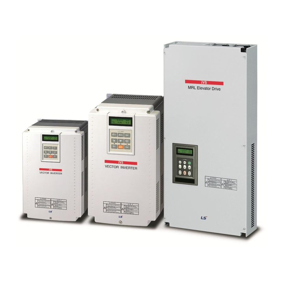
Chapter 1. BASICS Chapter 1 - Basics This instruction manual is designed for LS STARVERT-iV5(MRL: Machine Roomless Elevator) Inverters, which have excellent characteristics in speed and torque control with pulse encoder mounted on the shaft of 3 phase asynchronous motor, and covers installation, maintenance, wiring and operation for these inverters. -
Page 10: Inverter Model Name
Chapter 1. BASICS 1.2.2 Inverter Model Name SV [][][] iV5 - 4 (MRL) l LS STARVERT Series l Max. Applicable Motor 075 : 7.5kW ~ 220 : 22kW l Vector Inverter iV5 Series l Input Voltage 4 : 400V Class (380 ~ 480V) -
Page 11: Chapter 2 Installation And Wiring
Chapter 2. Installation and wiring Chapter 2 – Installation and wiring This chapter describes general items for the installation and wiring of an inverter and includes instruction for wiring to power terminal and control one and caution in case of wiring, and also explains the function of each terminal for both power and control. - Page 12 Chapter 2. Installation and wiring Min. 10 cm SV-iV5(MRL) Min. 5 cm Min. 5cm Min. 10 cm 2.1.7 Special care should be taken in case the inverter is to be installed in the panel. In case more than 2 inverters are to be installed or ventilation fan is to be installed in the panel, make sure that inverter and ventilation fan is properly installed.
-
Page 13: Basic Wiring
Chapter 2. Installation and wiring 2.2 Basic Wiring SV 075, 110, 150, 220iV5-4(MRL) DB Resistor (optional) MCCB 3P AC input STARVERT - iV5 PMSM (220/440V) (50/60Hz) Encoder (Line Drive Type) 24 V Shield Power supply (5V) Common(0V) FWD run /Stop command Encoder A Phase input REV run/Stop command... -
Page 14: Power Circuit Terminal
Chapter 2. Installation and wiring 2.3 Power Circuit Terminal SV075, 110, 150, 220iV5-4(MRL) P(+) N(-) 2.3.1 Power Circuit Terminal Description Name Function Description Connected to 3 phase input power supply 3 Phase input power supply R, S, T - 400V Class : 380 ~ 480V, 50/60Hz U, V, W Inverter Output Connected to 3 phase induction motor... - Page 15 Chapter 2. Installation and wiring ③ Cable between inverter output and motor should be less than 300m long. If cable gets long, surge voltage appears across motor terminals depending on the cable parameters. Especially, in 400V class motor case, insulation withstanding voltage may be decreased. Use an insulation-enforced motor when 400V class motor is used.
-
Page 16: Control Circuit Terminal
Chapter 2. Installation and wiring 2.3.4 Wiring DC Reactor (Option) (30kW and higher) When DC Reactor wiring, Connect like as figure below after removing common bar which is connected ① between P(+) and B1 of inverter terminal. P(+) B1 DC Reactor N(-) 2.4 Control Circuit Terminal 2.4.1 Control Terminal Layout... - Page 17 Chapter 2. Installation and wiring Item Name Function Description Power supply for VREF Reference voltage by variable resistor ( + 10V ) : 10kW analog setting Voltage signal input (-10 ~ 10V), current signal input (4 ~ 20mA), Motor NTC selectable via Multi-function Analog input. Selectable among following...
- Page 18 Chapter 2. Installation and wiring Item Name Function Description output 2 voltage, Inverter running, Inverter regenerating, Inverter ready, (A Contact) Timer output Open Collector Ouput Fault alarm A contact Outputs when fault occurs. Deactivated in BX condition. Fault alarm B contact COMMON COMMON for 30A, 30B Encoder Power Supply DC +5V / +12V / +15V selectable usages...
- Page 19 Chapter 2. Installation and wiring 2.4.5 Encoder Wiring and Switch Setting (Available for +12V/+15V Complementary or Open Collector, +12V / +15V power Type Encoder) S: I +15V Open Collector(DC) A+[PA] B+[PB] Z+[PZ] VREF AI1 A+[PA] B+[PB] Z+[PZ] VREF Shield Wire 2.4.6 Wiring and Switch Setting for Line Drive Type Pulse Encoder (+5V) ※...
- Page 20 Chapter 2. Installation and wiring CAUTION NEVER change the switch setting for Encoder Type during inverter run. Otherwise, it may cause inverter trip, adversely affecting the entire system. Therefore, verify the switch is correctly set before operation. 2.4.7 Jumper Setting for Analog Input (Voltage/Current/Motor NTC Input) ※...
-
Page 21: Appearance And Dimension
Chapter 2. Installation and wiring 2.5 Appearance and Dimension 2.5.1 SV 075, 110, 150, 220 iV5-4(MRL) 2.5.2 Dimension( mm[inches]) Capacity Φ 14 Φ7 MRL 075-4 97.2 64.7 [Φ0.55 [Φ0.28 MRL110-4 [12.99] [12.2] [0.28] [12.2] [26.7] [26.22] [3.83] [2.55] Φ 14 Φ7 108.5 75.7... -
Page 22: Chapter 3 Peripherals
Chapter 3. Peripherals 3.1 PeriPherals 3.1.1 MCCB(LS), ELB(LS), Magnetic contactor(LS), input/output wire specifications Wire (mm²) Magnetic Motor MCCB, Inverter models contactor U,V,W Ground R,S,T (kW) ELB (LS) (LS) SV075iV5-4DB ABS33b,EBS33b GMC-22 SV110iV5-4DB ABS53b,EBS53b GMC-22 400V SV150iV5-4DB ABS63b,EBS63b GMC-32 SV220iV5-4DB ABS103b,EBS103b GMC-50 3.1.2 AC input fuse, AC reactor, DC reactor... -
Page 23: Chapter 4 Loader And Basic Operation
Chapter 4 Loader and Basic Operation 4.1 Keypad operation LCD Keypad can display up to 32 alphanumeric characters and monitor or set parameter values to operate the inverter and the motor properly. As follows are keypad view and explanation on each key/LED on the keypad. 0.0rpm 0.0% 0.0A... -
Page 24: Keypad Lcd Display
Chapter 4 Loader and Basic Operation 4.2 Keypad LCD Display 4.2.1 LCD Start-up display 0.0rpm 0.0% 0.0A Function Description Motor speed Real motor speed in RPM (Revolution Per Minute) SPD: Speed control mode Motor control Mode TRQ: Torque control mode BX: Emergency stop Generating torque Displays generated torque to the 100% rated output of a motor. -
Page 25: Parameter Setting And Modifying
Chapter 4 Loader and Basic Operation 4.3 Parameter setting and modifying Inverter has a number of parameters. In case inverter is to be in use using a keypad, proper parameter values can be set depending on the load and operation condition. For more detailed information, refer to Chapter 6. -
Page 26: Parameter Group
Chapter 4 Loader and Basic Operation 4.4 Parameter group SV-iV5[MRL] series inverters use LCD keypad for user’s convenience. Data groups are divided into 7 groups for easy access depending on the inverter application. LCD keypad Name (on the upper Description left) Motor speed, Motor control mode, Generating torque, Output current, Display group... -
Page 27: Lcd Group Transfer In The Keypad
Chapter 4 Loader and Basic Operation 4.4.1 LCD Group transfer in the keypad For transfer to another group, [MODE] key is used and (Up), (Down) key is used to move up and down ▲ ▼ in the same group. Display group Input/output group Parameter group Function group... -
Page 28: Auto-Tuning
Chapter 4 Loader and Basic Operation 4.5 Auto-Tuning Measures stator resistance(Rs) of the synchronous motor by standstill auto tuning. 4.5.1 Motor & Encoder parameter setting for Auto-Tuning The parameters on the nameplate of the motor and the pulse number of encoder should be set before operation. -
Page 29: Standstill Auto-Tuning
None “ Rs Error ” displayed. If error occurs during auto-tuning, displayed. In this case, verify motor parameters and redo the auto-tuning. If the problem persists, contact LS customer PAR▶ Auto tuning service center . Rs Error FWD/REV LED on keypad will blink during Auto-tuning. -
Page 30: Encoder Operation Check
Chapter 4 Loader and Basic Operation 4.6 Encoder operation check 4.6.1 The definition of forward rotation Forward rotation is of counter-clockwise from the side view of motor shaft. Motor Forward totation 4.6.2 Forward rotaion check Be sure to check if positive(+) speed is displayed when inverter power is on and rotates the motor in the forward direction. -
Page 31: Permanent Motor Magnetic Flux Estimation Operation
Chapter 4 Loader and Basic Operation 4.7 Permanent motor magnetic flux estimation operation Before executing the operation, to run 4.5.1 Motor & Encoder parameter setting for Auto- Tuning is recommended. 4.7.1 Operation command source and speed command setting 1) RUN/STOP command by keypad Run/Stop Src ▶... - Page 32 Chapter 4 Loader and Basic Operation ① Low speed operation Check if motor speed is +10.0 rpm in the start-up LCD screen after pressing [FWD] key. +10.0 rpm Check if motor speed is –10.0 rpm in the start-up LCD screen after pressing [REV] key. -10.0 rpm In case that stimulus estimation is safely completed, operation status due to wrong wiring of encoder and motor at low speed operation is as follow.
-
Page 33: How To Set Roll-Back Prevention By Load Cell
Chapter 4 Loader and Basic Operation -100.0rpm 4.8 How to set Roll-back prevention by Load Cell 4.8.1 Preparations before setting 1) Input load detect signal such as Load cell at AI1-5G terminal 0~10V inputs come out. 2) During self-operation of inverter or other inverter, please check whether detect signal operates well or not. -
Page 34: Full Load Up Operation Preparations
Chapter 4 Loader and Basic Operation Connect OC1(multi-function output OC1) of SIO board and P7(multi- function output OC1) of CN4 with Jumper. Also, connect each EG of CN3 and CN4 of EG with Jumper. -> When Run, Analog Hold operation <... - Page 35 Chapter 4 Loader and Basic Operation <in case of ELIO operation mode> Please note torque value displayed on initial screen of keypad, setting Tq -100% MAN manual operation speed command as ‘0’. --F -50A In order to show torque value on keypad, please set value as “Trq Output” on E/L_58(Display Sel).
- Page 36 Chapter 4 Loader and Basic Operation Thus, calculation is as follow Keypad display Descriptions I/O▶ Ai1 Gain Input the value (AX100%) into I/O_13. 200% CON▶ Trq Balance Input the absolute value (BX(-)) into CON_35 100% 4-14...
-
Page 37: Chapter 5 Function Code Table
Chapter 5. Function Code Table 5.1 Display group(DIS_[][]) Setting Data Code Adjustment Function name LCD display Page during run Range Unit Default Motor speed/Control 0.0rpm SPD DIS_00 mode/generated 0.0% 0.0A torque/output current DIS_01 User display 1 Ai1 Value PreRamp Ref 6-2~3 Ai2 Value Ai3 Value... - Page 38 Chapter 5. Function code Table Run Status DIS_02 User select display 2 Refer to DIS_01 DC Bus Volt 6-2~3 DIS_03 User select display 3 Refer to DIS_01 Terminal In 6-2~3 PIDOut Process PID output 0.0% DIS_04 Ref / FB 0.0% 0.0% Malfunction status...
-
Page 39: Input/Output Group(I/O_[][])
Chapter 5. Function Code Table 5.2 Input/output group(I/O_[][]) Setting data Adjustme Functio Function name Page nt during n code display Range Unit Default Function code I/O_00 Jump Code 1 ~ 71 select Not Used Speed-L Speed-M Speed-H Jog Speed MOP Up MOP Down MOP Clear MOP Save... - Page 40 Chapter 5. Function code Table Multi-function Input Terminal I/O_09 0 ~ 2000 6-17 LPF time constant Negative function of multi-function Neg Func. 00000 I/O_10 00000 6-17 auxiliary output ~ 11111 terminal Not Used Speed Ref Proc PID Ref Proc PID F/B Multi-function I/O_11 analog input...
- Page 41 Chapter 5. Function Code Table Setting data Adjustm Functio Function name LCD display Page n code during Range Unit Default Not Used INV Ready Zero Spd Det Spd Det. Spd Det(ABS) Spd Arrival Timer Out LV Warn Definition multi- I/O_41 function 6-21~26 Regenerating...
- Page 42 Chapter 5. Function code Table Setting data Adjustme Functio Function name Page nt during n code display Range Unit Default Not Used Ai1 Value Ai2 Value Ai3 Value PreRamp Ref PostRamp Ref ASR Inp Ref Motor Speed Speed Dev ASR Out Torque Bias PosTrq Limit NegTrq Limit...
-
Page 43: Parameter Group(Par_[][])
Chapter 5. Function Code Table 5.3 Parameter group(PAR_[][]) Setting data Functio Adjustment Function name LCD display Page n code during run Range Unit Default PAR_00 Function code select Jump Code 1 ~ 41 6-30 All Groups PAR_01 Initialize parameters Para. init 6-30 PAR_02 Read parameters... - Page 44 Chapter 5. Function code Table Functio Setting data Adjustment Code name LCD display Page n code during run Range Unit Default PAR_17 Motor base speed Base Speed 10.0 ~ 3600.0 6-36 PAR_18 Motor rated voltage Rated Volt 120 ~ 560 6-36 PAR_19 Motor number of poles...
-
Page 45: Function Group(Fun_[][])
Chapter 5. Function Code Table 5.4 Function group(FUN_[][]) Setting data Function Adjustment Function name Page code display during run Range Unit Default FUN_00 Function code select Jump code 1 ~ 66 6-39 Terminal 1 RUN/STOP command Run/Stop Terminal 2 FUN_01 Terminal 1 6-39~40 source selection... - Page 46 Chapter 5. Function code Table Function Setting data Adjustment Function name Page code display during run Range Unit Default FUN_53 Hold Time Hold Time 100 ~ 10000 1000 6-47 Electronic thermal FUN_54 ETH Select No/Yes 6-48~49 selection Electronic thermal FUN_55 level ETH 1 min FUN_56 ~ 200...
-
Page 47: Control Group(Con_[][])
Chapter 5. Function Code Table 5.5 Control group(CON_[][]) Setting data Function Adjustment Function name Page code display during run Range Unit Default CON_00 Function code select Jump Code 1 ~ 49 6-53 Control Speed CON_01 Control mode setting Speed 6-53 Mode Torque Application... - Page 48 Chapter 5. Function code Table Function Setting data Adjustment Function name Page code display during run Range Unit Default Torque CON_27 Torque Ref -180.0 ~ 180.0 6-61 Reference(keypad) Kpd Kpd Kpd Kpd Kpd Ax Kpd Ax Kpd Kpd Ax Ax Torque limit source CON_28 Trq Lmt Src...
-
Page 49: User Group(Usr_[][])
Chapter 5. Function Code Table 5.6 User group(USR_[][]) Function Setting data Adjustment Function name Page code display during run Range Unit Default USR_00 Function code select Jump Code 1 ~ 67 6-66 User Define USR_01 Initialize Macro Macro Init User Define 6-66 USR_02 User data save... -
Page 50: Chapter 6 Function Description
Chapter 6. Function Description (I/O) Chapter 6 – Function Description 6.1 Display group (DIS_[][]) 6.1.1 DIS_00 (Motor control status monitoring) Displayed when Power ON. Motor control mode Motor speed 0.0rpm 0.0% 0.0A Output current Output torque Code Parameter name Unit Description Motor speed Actual motor rotating speed displayed in rpm. - Page 51 Chapter 6. Function Description (I/O) Code Parameter name LCD display Unit Description Negative Trq Limit Neg Trq Limit Negative torque limit to rated torque Regeneration Trq Limit Reg Trq Limit Regeneration torque limit to rated torque Torque Reference Torque Ref Torque reference to rated torque Torque current ref.
-
Page 52: Dis_04(Process Pid Controller)
Chapter 6. Function Description (I/O) 6.1.3 DIS_04 (Process PID Controller) Information on Output, reference, F/B values of Process PID controller is displayed in this code. Process PID output PIDOut 0.0% 0.0% 0.0% Process PID F/B value Process PID reference value 6.1.4 DIS_05 (Fault display) Current fault status, previous two faults, the number of faults occurred and faults information reset are available using [SHIFT/ESC] key in DIS_05. -
Page 53: Dis_06(User Group Display Selection)
Chapter 6. Function Description (I/O) ※ Note : When multiple faults occur at the same time, the MOST CRITICAL fault will be displayed and the rest of others can be inferred from the value using [PROG], [▲(Up)] / [▼(Down)] keys . 6.1.5 DIS_06(User group display selection) User can make “User group”... -
Page 54: Jump Code (I/O_00)
Chapter 6. Function Description (I/O) 6.2 I/O group (I/O_[][]) 6.2.1 Jump code (I/O_00) In I/O_00, jumping directly to any parameter code can be accomplished by entering the desired code number. (Example) Moving to I/O_05 Press [PROG] and set to 5 using [SHIFT/ESC] / [▲(Up)] / [▼(Down)] and press [ENT] key to move to I/O_05. If the desired code cannot be set, the closest code will be displayed. - Page 55 Chapter 6. Function Description (I/O) 1.1) Speed-L 1.2) Speed-M 1.3) Speed-H 1.4) JOG operation By defining P1 ~ P4 as “Speed-L”, “Speed-M”, “Speed-H” and “Jog Speed”, the selected references in FUN goup 12 ~ 20 (Multi-step speed 0 ~ 7 and Jog speed) become active as speed reference. (Example) To define Multi-function input terminals P1, P2, P3 as Speed-L, Speed-M, Speed-H and P4 as Jog Speed;...
- Page 56 Chapter 6. Function Description (I/O) retained. When the MOP operation resumes, the retained value will be used as speed reference. “MOP Clear” resets the MOP Data value to “0”. It is used to change the saved value. (Example) MOP function setting and operation method is as follows; Setting Code Description...
- Page 57 Chapter 6. Function Description (I/O) (MOP Save example 2) In case terminal input assigned to MOP Save function is ON, operation speed at that instant is memorized and operates at the saved speed when operation resumes. Saved speed ref. by “MOP Save”...
- Page 58 Chapter 6. Function Description (I/O) (MOP Clear setting example 3) To clear the saved speed by MOP Save function, use “MOP Clear ON/OFF”. If MOP Clear is ON during running, the inverter decelerates its speed to zero speed. If MOP is ON during stop, this function resets the speed reference to “0”.
- Page 59 Chapter 6. Function Description (I/O) 1.9) Analog Hold When FUN_02 is set to “analog” and one of the selected terminal set to “Analog Hold” is ON, inverter fixes its output frequency, regardless of the frequency reference change. The changed frequency reference is applied when the terminal is OFF.
- Page 60 Chapter 6. Function Description (I/O) ※ Cross reference table for 1 function and& 2 function Parameter function function Acceleration time 2nd_09 2nd Acc time FUN_40 Acc. Time 1 Deceleration time 2nd_10 2nd Dec time FUN_41 Dec. time 1 Encoder-related 2nd_12 ~ 2nd_14 PAR_11 ~ PAR_15 parameter Motor constants...
- Page 61 Chapter 6. Function Description (I/O) 1.14) 3-Wire operation When FX or RX terminal is turned ON and turned OFF, the terminal is maintained ON using this parameter. (Operating method when P2 is set to 3-Wire) P2(3-Wire) SPEED[rpm] FORWARD REVERSE P2(3-Wire) TIME [3 Wire operation] 1.15) Ext Trip-B (External trip signal input by b contact)
- Page 62 Chapter 6. Function Description (I/O) 1.16) Prohibit FWD (Prohibition of Forward Rotation) 1.17) Prohibit REV (Prohibition of Reverse Rotation) If Prohibit FWD or Prohibit REV is set, it prohibits forward or reverse rotation, respectively. If Prohibit FWD is used, speed command becomes 0 when it has positive value. Similarly, If Prohibit REV is used, speed command becomes 0 when it has negative value.
-
Page 63: I/O_01 ~ 07(Multi-Function Input Terminal P1 ~ P7 Define)
Chapter 6. Function Description (I/O) Proc PID Dis Operating reference CON_20 Multi-function input signal Disable Disable Terminal Enable Disable Enable Enable Disable Disable Disable Disable 1.19) Timer Input The multi-function input terminals P1~P7 can generate the timer output based on the timer ON delay time at I/O_55 and timer Off delay time at I/O_56. - Page 64 Chapter 6. Function Description (I/O) (Example) Programming P3 as SoftStrtCncl P1 (Xcel-L) P2 (Xcel-H) P3 (SoftStartCncl) Accel/Decel time Accel/Decel 1 Accel/Decel 2 Accel/Decel 3 Accel/Decel 4 The shortest Accel./Decel. 1.21) ASR Gain Sel (Switch Automatic Seed Regulator PI gain) Using ‘ASR Gain Sel’ function, one of the two P and I gains can be selected for PI speed controller (ASR). (Example) Programming P5 as ASR PI Gain Code LCD display...
-
Page 65: I/O_08(Reversal Of Multi-Function Input Terminal)
Chapter 6. Function Description (I/O) 1.25) Spd/Trq Sel (Speed/Torque Control Transfer) Speed and torque control can be switched using this function. This terminal input overrides the input from the keypad. 1.26) Use Max Torque (Maximum Torque Enable) If this input is ON, the torque limit value of the speed controller is fixed to its maximum value. On the contrary, when this input turns off, the value defined at CON_29 ~ CON_31 applies to torque limit value. -
Page 66: I/O_10Inversion Of Multi-Function Aux Contact Output
Chapter 6. Function Description (I/O) 4) I/O_10 Inversion of Multi-function aux contact output (Relay output, Open collector output) Factory default settinf of Multi-function Relay outputs is A contact. To change it to B contact, set it to “1”. See the below for setting example: (terminal layout is AX1, AX2, OC1, NC, NC from left.) (Setting example) (AX1 ~ OC1: A contact) (AX1, OC1: B contact) - Page 67 Chapter 6. Function Description (I/O) Code setting related to multi-function analog input is shown in the table below. Code Display Description Range Unit Default Speed Ref Proc PID Ref Proc PID F/B Multi function analog input Draw Ref I/O_11 Ai1 Define Not Used Definition of Ai1 Torque Ref...
-
Page 68: Adjusting Gain And Bias By Keypad
Chapter 6. Function Description (I/O) 2) Adjusting Gain and Bias by Keypad Gain Adjustment: Supply 10V to terminal Ai1 and follow next steps. (The same procedure is applied to Ai2/Ai3. Set the potentiometer High (Max).) LCD Display Description I/O▶ Ai1 Gain Initial Gain (Factory setting) 100.00 % When pressing the [PROG] key, current output [%] to input... -
Page 69: Multi Function Outputs (Mfo)
Chapter 6. Function Description (I/O) 6.2.4 Multi Function Outputs (MFO) 1) I/O_41 ~ 43 (Multi-function aux contact output (AX1 ~ AX2) and Open collector (OC1) output setting) Multi-function digital output terminal serves as one of the functions listed in the table below. Multi-function aux contact is activated when the selected function is ON. - Page 70 Chapter 6. Function Description (I/O) SPEED I/O_48 I/O_47 Detection CLOSE OPEN CLOSE signal TIME 1.4) Spd Det. – Polarity valid 1.5) Spd Det.(ABS) – Polarity invalid This is ON when the real motor speed reaches the arbitrary speed. The polarity of detecting speed is valid for Spd Det. But, the polarity is invalid for Spd Det(ABS).
- Page 71 Chapter 6. Function Description (I/O) 1.6) Spd Arrival It detects whether the motor reaches the set speed band. Code Display Description Range Unit Default I/O_51 SA Band SA hysterisis band 0.1~10.0 1.7) Spd Agree This is ON when the motor speed becomes equal to the set speed. Code Display Description...
- Page 72 Chapter 6. Function Description (I/O) MultiFunction Input I/O_55 I/O_56 MultiFunction Output Timer ON Delay Timer OFF Delay 1.9) LV Warn LV is enabled when the DC link voltage of the inverter is less than the detecting level of low voltage alarm. 1.10) Run It is ON when the inverter is running.
- Page 73 Chapter 6. Function Description (I/O) 1.15) Trq Lmt Det Trq Lmt Det is ON when the output of ASR (Torque reference) is saturated so that its limit value is generated. 1.16) OverLoad Overload is ON when the inverter output current is higher than the overload alarm level. (On the basis of the rated current of the motor) Refer to the following values of overload alarm level (I/O_57) and overload alarm time (I/O_58).
-
Page 74: I/O_46(Fault Output Relay (30A, 30B, 30C))
Chapter 6. Function Description (I/O) 2) I/O_46 (Fault Output Relay (30A, 30B, 30C)) This function can be used when the inverter fault signal is generated through the relay contact. the fault alarm is triggered differently by setting the bits related to the low voltage trip, inverter trip and the number of retry. Code Display Description... - Page 75 Chapter 6. Function Description (I/O) Setting Description Output signal level AiX Value Analog input value +10 V: 10V, 20mA PreRamp Ref Pre Ramp Reference +10 V: Max Speed PostRamp Ref Post ramp reference +10 V: Max Speed ASR Inp Ref ASR Input Reference +10 V: Max Speed Motor Speed...
-
Page 76: Parameter Group (Par_[][])
6.3 Parameter group (PAR_[][]) 6.3.1 Jump code (PAR_00) In PAR_00, jumping directly to any parameter code can be accomplished. (Example) Moving to PAR_30 Press [PROG] and set to 30 using [SHIFT/ESC] / [▲(Up)] / [▼(Down)] and press [ENT] key. If the desired code cannot be set (void), the nearest code will be displayed. -
Page 77: Par_04(Parameter Lock)
PAR▶ Para. read --- Yes --- Remove the keypad. PAR▶ Para. write --- Yes --- Install it to the copied inverter. 3) PAR_04 (Parameter Lock) Set it to “12” to disable “paramter change”. Factory Code LCD display Description Setting range Unit setting PAR_04... -
Page 78: Motor Parameters Setting
6.3.3 Motor parameters setting 1) PAR_07(Motor rating setting) Company Capacity (Kw) Ex) Company 1 3.7kW, 6.2kW, 6.5kW, 7.1kW, 12.5kW, 14.1Kw Ex) Company 2 3.7kW, 6.2kW, 6.5kW, 7.5kW, 11kW, 15Kw Ex) Company 3 13.3kw Ex) Company 4 6.7kw * Advise to compare and validate set up values with motor ratings’ plate, since PAR_17, 18, 19, 20, 21, 22, 28, and 30 are to change automatically upon motor capacity selections. -
Page 79: Encoder S/W Error Detection
signal may be less affected by the electromagnetic noise signal by adjusting PAR_13 (Encoder LPF Time Constant). Code LCD display Description Setting range Factory setting PAR_11 Enc Dir Set Encoder direction setting A Phase Lead/B Phase Lead A Phase Lead Setting Description Encoder pulse (In FWD RUN) - Page 80 Factory Code LCD display Description Setting range Unit setting PAR_14 EncFaultTime Encoder error detection time 0.00 ~ 10.00 0.00 Encoder error reference PAR_15 EncFaultPerc 0.0 ~ 50.0 25.0 speed PAR_21 Rated-Slip Motor rated slip 10 ~ 250 When encoder/motor wiring is reversed, motor cannot perform acceleration due to overcurrent. Encoder S/W error detection is adopted to detect the errors such as wrong wiring and incorrect pulse input during normal operation, not during Auto-tuning.
-
Page 81: Auto-Tuning
6.3.5 Auto-Tuning The motor parameters for the Vector Control are autotuned by Starvert-iV5. The stator resistance, Stator Inductance, Leakage Inductance and Rotor time constant are found and saved. User can select the type of Auto-tuning in Rotational or Standstill mode. -
Page 82: Par_35 (Repetition Numbers For Magnetic Flux Detection)
2) PAR_35 (Repetition numbers for magnetic flux detection) Display repetition number of magnetic flux detection operations Function Loader Function Name Setting Range Unit Default Value Code Display Repetition number for PAR_35 DetAve Num 1~30 magnetic flux detection 3) PAR_36 (Magnetic flux detection voltage) Set up the size of supplied voltage pulse when magnetic flux detection is running. - Page 83 First Bit : Output phase loss Second Bit : Input phase loss Third Bit : Magnetic Detection Error Fourth Bit : Speed Deviation Error 8) PAR_41 (Operation command accumulated value for repetition of magnetic flux estimation) Function Loader Function Name Setting Range Unit Default Value...
-
Page 84: Function Group (Fun_[][])
Chapter 6. Function Description (FUN) 6.4 Function group (FUN_[][]) 6.4.1 Jump code (FUN_00) Jumping directly to any parameter code can be accomplished using FUN_00 [Jump code]. Press [PROG] key first and set 2 using [▲(Up)], [▼(Down)], [SHITF/ESC] and press [ENT] key to jump to FUN_02. If the desired code cannot be accessed or void, it automatically jumps to closest code. -
Page 85: Fun_02(Speed Setting Method)
Chapter 6. Function Description (FUN) 2) FUN_02 (Speed setting method) There are four methods to set operating speed. Keypad 1/Keypad 2: Digital setting via keypad Analog: speed setting via analog input terminal define Option: speed setting via option card To change speed reference in Keypad 1 method, change the value in FUN_12 Speed 0 using [▲(Up)], [▼(Down)] key and press [ENT] key to enter the value into memory. -
Page 86: Fun_20(Jog Speed Command)
Chapter 6. Function Description (FUN) Setting speed Speed command source is selected at FUN_02. (One of analog inputs, FUN_12 and Option board) FUN_13 FUN_14 FUN_15 FUN_16 FUN_17 FUN_18 FUN_19 FUN_20 (JOG speed command) The values of the multi-step speed command are shown below. Factory Code LCD display... -
Page 87: Accel/Decel Pattern And Time Selection
Chapter 6. Function Description (FUN) 6.4.5 Accel/Decel pattern and time selection 1) FUN_33 (Accel/Decel reference speed) Acceleration time, deceleration time and BX time is set on the basis of the value at FUN_33(Accel./decel. reference speed), which is ‘Max speed’or ‘Ref speed’ . (Setting example 1) if FUN_33= “Max Speed”, Max motor speed= 3000rpm and Operating speed= 1500rpm, Accel time= 5 sec, accel time from 0 (stop) to 1500rpm would be 2.5 sec. -
Page 88: Fun_36 ~ 39(S Curve Ratio During Accel/Decel 1 ~ 2)
Chapter 6. Function Description (FUN) (Example) Code setting in case that using multi function input terminal P1, P2 Code LCD display Description Setting range Unit Factory setting I/O_01 P1 define Definition of P1 input Xcel – L I/O_02 P2 define Definition of P2 input Xcel –... - Page 89 Chapter 6. Function Description (FUN) Programming example of S curve pattern Speed Acceleration St _ time time St _ time Basic equation St1_time = AccTime * (FUN_36 / 50.0%) St2_time = AccTime * (FUN_37 / 50.0%) St1_ Δ rpm = St1_time * (MaxSpeed / AccTime) * 0.5 St2_ Δ...
-
Page 90: Fun_48(Deceleration Time For Zero Speed Selection)
Chapter 6. Function Description (FUN) Drpm : Speed difference : Maximum speed ( FUN_04 ) MaxSpeed : Set acceleration time (FUN_40, 42, 44, 46) AccTime St1_Drpm : Acc S Start ST (%) of FUN_36 at the time of acceleration, Dec S End ST (%) of FUN_39 at the time of deceleration St2_Drpm : Acc S End ST (%) of FUN_37 at the time of acceleration, Dec S Start ST (%) of FUN_38 at the time of deceleration St1_time : The time when St1_Drpm is formed. -
Page 91: Fun_53(Hold Time)
Chapter 6. Function Description (FUN) Run command Speed Flux current 200% of rated flux current 500(ms) Time Pre-excitation Stopping Speed control zone time 8) FUN_53(Hold Time) The motor maintains the zero speed for ‘Motor Hold Time’ after the motor decelerates to a stop. Code LCD display Description... -
Page 92: Electronic Thermal (Motor I T 2 ) Selection
Chapter 6. Function Description (FUN) 6.4.6 Electronic Thermal (Motor ) Selection These functions are required when the motor should be protected against the overheat without installing the thermal relay between the inverter and the motor. If electronic thermal protection is ON, the inverter blocks the IGBT gating signals and issues the trip message. -
Page 93: Inverter Switching Frequency Select
Chapter 6. Function Description (FUN) Load Current (%) [ETH 1min] [ETH cont] FUN_55 FUN_56 Trip Time 1 minute [Motor i t Characteristic Curve] The motor protection is possible by calculating and accumulating I t even in load variation and frequent run/stop. 6.4.7 Inverter switching frequency select 1) FUN_57 (Inverter switching frequency select) This parameter affects the audible sound of the motor, noise emission from the inverter, inverter... -
Page 94: Power On Start Selection (Fun_58)
Chapter 6. Function Description (FUN) 6.4.8 Power ON Start Selection (FUN_58) In case ‘No’ is set, the inverter can be operated only if the terminal should be ‘On’ again after it is ‘Off’ once. In case ‘Yes’ is set, the inverter starts to run at the instant the power is supplied to the inverter if FX terminal input is ‘On’... -
Page 95: Wait Time For Restart Upon Stop
Chapter 6. Function Description (FUN) Code LCD display Description Setting range Unit Factory setting Number of auto restart FUN_60 Retry Number 0 ~ 10 Delay time before FUN_61 Retry Delay 0.0 ~ 60.0 Auto restart In case the inverter trip occurs, the inverter restarts by ‘The number of automatic restart’ at FUN_60. In case of the inverter trip, the inverter resets the fault automatically and waits for ‘Delay time before automatic restart’... -
Page 96: Overspeed Error Detection (Fun_63,Fun_64)
Chapter 6. Function Description (FUN) Target speed Motor Actual speed Speed FX(or RX) TIME FUN_62(Restart Time) 6.4.12 Overspeed error detection Inverter detects error if motor rpm exceeds its limit. User can set the detection level and time of overspeed. Code LCD display Description Setting range... -
Page 97: Control Group (Con_[][])
Chapter 6. Function Description (CON) 6.5 Control group (CON_[][]) 6.5.1 Jump code (CON_00) Jumping directly to any parameter code can be accomplished using CON_00 [Jump code]. Press [PROG] key first and set 11 using [▲(Up)], [▼(Down)], [SHITF/ESC] and press [ENT] key to jump to CON_11. If the desired code cannot be accessed or void, it automatically jumps to closest code. -
Page 98: Con_03 ~ 04(Asr Pi Gain 1)
Chapter 6. Function Description (CON) (Example) Programming P4 as ASR PI Gain Code LCD display Description Setting range Unit Set value Multi-function input terminal I/O_04 P4 define ASR Gain Sel P4 definition The two sets of Lowpass Filter are as follow: Code LCD display Description... - Page 99 Chapter 6. Function Description (CON) Code LCD display Description Setting range Unit Factory setting Ramp time for ASR gain CON_09 ASR Ramp 10 ~ 10000 1000 switch-over Target Speed after ASR CON_10 ASR TarSpd 0.0 ~ 3600.0 gain switch-over Gain Ramp time CON_09 CON_03 CON_06...
-
Page 100: Process Pid Control
Chapter 6. Function Description (CON) 6.5.5 Process PID Control Process PID controller is added ouside the speed control loop and a wide variety of process control can be implemented without using the stand-alone PID controller outside the speed control loop or PLC. ‘Process PID Enb’ at CON_20 determines whether Process PID controller is enabled or not. - Page 101 Chapter 6. Function Description (CON) The definition of P gain and I gain in the Process PID controller is as follows. If P gain is 100% and I gain is 0% and the input error of the Process PID controller (CON_11 + Proc PID Ref - Proc PID F/B) is 100%, the output of Process PID controller is 100%.
-
Page 102: Draw Control
Chapter 6. Function Description (CON) 6.5.6 Draw Control Draw control is a sort of Open Loop tension control. Draw is the ratio of speed difference between one roll and the other. Tension is generated as in the following equation. INVERTER 1 INVERTER 2 Draw Setting Line Speed Setting... - Page 103 Chapter 6. Function Description (CON) Draw reference multiplied by draw quantity set at CON_22 is added up to the speed command and the sum acts as the final speed command. Accel/Decel Speed Routine CON_22 Draw Quantity (%) Process PI output -100 ~ 100% Draw Ref Draw Control Setting...
-
Page 104: Droop Control
Chapter 6. Function Description (CON) 6.5.7 Droop Control Droop control uses the drooping characteristic of the speed with respect to the torque reference. This control method is used to prevent the saturation of the speed controller due to the difference between the speed reference and the real speed when the inverter is used for load balancing of the multiple motors and helper roll, which is the auxiliary device of the main roll. - Page 105 Chapter 6. Function Description (CON) (( Droop Control Calculation )) When Torque Ref is Positive: Droop Ref speed = ( Torque Ref [%] - Droop Starting Torque[%] ) * Droop Quantity[%] The result value becomes positive. Therefore, final speed ref value decreases and it should be, (Speed Ref –...
-
Page 106: Torque Control
Chapter 6. Function Description (CON) 6.5.8 Torque Control One mode among the speed control mode and torque control mode can be set at CON_01( ‘Control Mode’). The default is the speed control mode. Control mode can be selected using the multi-function terminal input set to ‘Speed/Torque control selection’. -
Page 107: Con_35(Torque Balance)
Chapter 6. Function Description (CON) 3) CON_35 (Torque Balance) In the lift use, the load torque balance can be adjusted to obtain a good riding comfort at start-up using the load cell, which is a sort of an weighing devices installed at the bottom of the lift. CON_35 is adjusted to show 50% after the car weight becomes equal to the weight of counter-weight. - Page 108 Chapter 6. Function Description (CON) Output torque (FWD) Regenerating torque limit Positive torque limit Regenerating Motoring Motor rpm (REV) Motor rpm (FWD) Motoring Regenerating Negative torque limit Regenerating torque limit Output torque (REV) Torque Limit Torque Limit value is determined one of the 9 different combinations shown below depending on CON_28 setting. CON_28 Regenerating Positive Torque Limit...
-
Page 109: Speed Search (Con_49)
Chapter 6. Function Description (CON) 6.5.9 Speed Search This is used to restart the motor during coasting without stopping the motor. CON_49 are required for this function. The proper values should be set depending on the inertia moment (GD²) of the load and the torque of the motor in use. Setting Factory Code... -
Page 110: User Group (Usr_[][])
Chapter 6. Function Description 6.6 User Group (USR_[][]) User group can be generated by collecting the frequently-used function codes, and it also can be created by using the existing function codes for the specific application. 6.6.1 Jump code (USR_00) Jumping directly to any parameter code can be accomplished using USR_00. (Example) Jumping to USR_03 Press [PROG] key first and set 3 using [▲(Up)], [▼(Down)], [SHITF/ESC] and press [ENT] key to jump to USR_03. - Page 111 Chapter 6. Function Description Total 64 user group data can be programmed and saved. To make the unused data invisible, set it to “Not Used”. Changing User group codes USR▶ User Grp Not Used Press the [PROG] key once. USR▶ User Grp Not Used Pressing the [PROG] key once more and press the [SHIFT/ESC] key to change the group.
-
Page 112: Chapter 7 Control Block Diagram
Chapter 7 – Control Block Diagram... -
Page 113: Block Diagram
Chapter 7 – Control Block Diagram... - Page 114 Chapter 7 – Control Block Diagram...
- Page 115 Chapter 7 – Control Block Diagram...
- Page 116 Chapter 7 – Control Block Diagram...
- Page 117 Chapter 7 – Control Block Diagram Accel/Dece timel...
- Page 118 Chapter 7 – Control Block Diagram...
- Page 119 Chapter 7 – Control Block Diagram...
- Page 120 Chapter 7 – Control Block Diagram...
- Page 121 Chapter 7 – Control Block Diagram...
- Page 122 Chapter 7 – Control Block Diagram Operating direction...
- Page 123 Chapter 7 – Control Block Diagram...
- Page 124 Chapter 7 – Control Block Diagram...
-
Page 125: Fault Display
Chapter 8 Troubleshooting & Maintenances 8.1 Fault display Caution When a fault occurs, the inverter turns off its output and displays the fault status described below. In this case, the cause must be corrected before the fault can be cleared. If protective function keeps active, it could lead to reduction in product life and damage to the equipment. -
Page 126: Checking Fault Status And History
Chapter 8 Troubleshooting & Maintenances Protective Keypad Description function display Used for the emergency stop of the inverter. The inverter instantly turns off the BX protection output when the BX terminal is turned ON, and returns to regular operation (Instant Cut Off) when the BX terminal is turned OFF. -
Page 127: Faulty Remedy
Factory default: Line Drive Type 3) Is motor rotating direction set correctly? ☞ Refer to Monitoring Encoder operation STARVERT-iV5[MRL] defines Forward rotation when motor rotates in clockwise from the view of Rear Bracket (Motor FAN). 4) Is inverter operating correctly in no load condition? ☞... - Page 128 ☞ check the motor nameplate and setting matches. (7) Is PAR_26 [motor flux current] properly set? ☞ If LG-OTIS vector motor is not used, consult LS representative or set the correct value in accordance with application. However, it cannot set to exceed PAR_22 [motor rated current].
- Page 129 ☞ CON_29 ~ CON_31 marks upper limit in inverter output torque. For the application lower torque limit is required, when torque shortage occurs, increase this value a little. STARVERT-iV5 ‘s overload capacity is 180%/1 min. when using torque limit over 180%, time and the number of use should be limited.
- Page 130 Refer to 16). 7) Operating speed does not change during run. (1) Is FUN_02 speed setting proper? ☞ Speed setting methods in STARVERT-iV5 are Analog input, Keypad and Option. Select appropriate one among them. (2) Is DIS_01(PreRamp Ref) setting the correct value? ☞...
- Page 131 ☞ Check the inverter and Keypad connection. (2) Is input power turned on ? ☞ Check inverter power is applied. If nothing is displayed on the LCD in this condition, contact LS representatives. 11) Motor speed oscillates and speed is not constant during constant Run.
- Page 132 ☞ Poor encoder and motor connection may generate slip. Check the connection is tight. 12) Parameter change is not saved. ☞ Turn the power off and turn it on. If problem persists, contact LS representatives. 13) Motor input current is too large.
-
Page 133: Lists For Maintenance And Check
8.5 Lists for maintenance and check Machine Roomless Elevator of LS industrial systems for STARVERT-iV5(MRL) is an industrial product with s high technology semiconductor device that may have malfunction due to product life expired and environmental factors such as temperature, humidity, vibration. -
Page 134: Regular Check
Chapter 8 Troubleshooting & Maintenances 8.5.2 Regular check 1) Check whether bolts and nuts are looses or corroded. ☞ Please, fasten or change bolts and nuts since they could be looses or get rusty in environment with excessive vibrations. 2) Check whether cooling plate inside the inverter are covered with foreign substances or not. ☞... -
Page 135: Chapter 9 Specifications And Option Devices
Chapter 9 Specifications and Option devices 9.1 Standard specifications 1) 400V class SV[][][]iV5-4(MRL) [HP] Max. applicable motor [kW] Capacity 13.7 20.6 27.5 39.6 (note 1) [kVA] Rated current [A] Output Output 0 ~ 200(rpm) speed Output (주2) 380 ~ 480V voltage (주3) 3f 380 ~ 480V(-10% ~ +10%) -
Page 136: Common Specifications
Chapter 9 Specifications and Option devices 9.2 Common specifications Items Specifications Inverter type Voltage source inverter using IGBT Field oriented vector control inverter using Encoder feedback (5.5 ~ Control method 220kW) l Analog setting: ± 0.2%(25 ± 10℃) of max. Speed Speed control accuracy l Digital setting : ±... - Page 137 Chapter 9 Specifications and Option devices Items Specifications l 2 channels (AO1, AO2) Analog l -10V ~ 10V Voltage output output l Selectable among 31 different user-defined functions l 2 channels (1A-1B, 2A-2B) Contact output l Fault alarm relay: 1 channel (30A-30C, 30B-30C) Open Collector 1 Channel (OC1/EG) Overcurrent, Overvoltage, Low voltage, Inverter overheat, Inverter...
-
Page 138: Breaking Resister Specifications
Chapter 9 Specifications and Option devices 9.3 Braking resister specifications 1) Braking resister specifications per capacity (note 1) Resistances on the chart below are calculated based on braking torque 150%, 5% ED When using 10% ED, please make rated watt of the resistor double. Capacity (5% ED) Applicable Type... -
Page 139: Encoder Division Option Card(Open Collector)
Chapter 9 Specifications and Option devices 9.4 Encoder division option card(open collector) 9.4.1 How to treat encoder division option card Please, attatch CN2 coneector of encoder division option card to CN4 connector of control board. ▶ Control board Encoder division Option card S: I ▶... - Page 140 Chapter 9 Specifications and Option devices peripheral controller: B phase RT_B encoder B phase division output input peripheral controller: GND Encoder division output function Only in case of having encoder division output option card, this function is available. When connecting encoder output with pulse input device of peripheral equipment, set division비. Function Keypad Function name...
-
Page 141: Warranty
Damage was caused by misuse, negligence or accident. l Damage was caused by abnormal voltage and peripheral devices’ malfunction (failure). l Damage was caused by improper repair or altering by other than LS authorized distributor or service center. l Damage was caused by an earthquake, fire, flooding, lightning, or other natural calamities. - Page 142 Revision History Date Edition Changes Oct, 2006 First Release Ver. 1.00...
Need help?
Do you have a question about the STARVERT-iV5 and is the answer not in the manual?
Questions and answers