Table of Contents
Advertisement
Quick Links
Advertisement
Table of Contents

Related Manuals for Topcon SR-NIR


Summary of Contents for Topcon SR-NIR
- Page 1 INSTRUCTION MANUAL SPECTRORADIOMETER Rev.8...
- Page 3 Thank you for your purchasing Topcon Technohouse Corporation Spectroradiometer SR-NIR. The spectroradiometer SR-NIR can measure the spectral distribution of PDP, CRT, LCD, the back light of LCD, and the reflected light of luminous bodies such as LED, coated surfaces and printed substances.
-
Page 4: Display For Safe Use
Display for Safe Use The instruction panels on the device and this Instruction Manual describe important things to prevent the dangers to the operator or others and damages to your properties from occurring, and to secure your operating this device. Be sure to understand the following indications and symbols, read the precautions and the contents, and observe the written instructions fully. - Page 5 AC adapter cable from the outlet. Continuing to use the device may cause the fire. Forced Please contact the local retailer from which you purchased the device or TOPCON TECHNOHOUSE CORPORATION.
- Page 6 Caution Symbols Precautions Never watch the Sun or the filament of an electric bulb directly. This may injure your eyes. Prohibited Never put the device (or other objects) on the unstable places like wobbly table or inclined surface. Dropping or falling of the device (or other objects) may injure you. Prohibited Never pull out or insert the plug by wet hand.
- Page 7 (for example, in a car). • To maintain the measurement precision, be sure to perform the calibration at least once a year. For the calibration, consult the local retailer from which you purchased the instrument or TOPCON TECHNOHOUSE CORPORATION.
- Page 8 User Maintenance Maintenance works other than instructed in this manual must not be carried out by anybody other than our servicing staff in order to keep the safety and performance. However, the following matters can be performed by the user for maintenance. Please read the section relevant to the maintenance method in this Manual.
-
Page 9: Table Of Contents
Table of Contents Introduction Display for Safe Use Conventions in This Manual Before Use ............................1 Checking the Instrument and Accessories ................1 Names and Functions of Components ..................2 Preparations ..........................7 1.3.1 Connecting AC Adapter ..................... 7 1.3.2 Connecting PC ........................ - Page 10 Data Communication Method ....................38 Terminal Code of Remote Command ..................39 Using Correction Factor ......................40 3.10 Display/Change of Correction Factor ..................41 3.11 Average Measurement ......................43 3.11.1 Average Times ........................ 44 3.12 Selecting “OVER-RANGE” Detection in “MANU” Mode ............45 3.13 Beep Sound ..........................
- Page 11 Specifications and Performance ......................69 Block Diagram ............................71 External Dimensional Diagram ......................72...
-
Page 12: Conventions In This Manual
Conventions in This Manual Description in this Manual is in accordance with the following notation. Notation Description [FUNCTION], This indicates the menu titles displayed on the panel switch or the liquid [UP] crystal display (LCD) unit. ☞ 「」 This shows the reference section within the Manual. ☞... -
Page 13: Before Use
1.1 Checking the Instrument and Accessories Please check the instrument and all of the accessories shown below are provided. If any of them is not found, please contact the local retailer from which you purchased the instrument or TOPCON TECHNOHOUSE CORPORATION. • Main body SR-NIR •... -
Page 14: Names And Functions Of Components
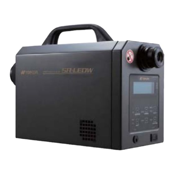
1.2 Names and Functions of Components ■ Instrument body Eyepiece lens Diopter adjustment ring Handle Focus adjustment ring Objective lens External synchronizing signal input connector Liquid crystal (LC) contrast adjustment volume RS-232C connector USB connector Reset switch Used to bring the viewfinder’s reticle mark into focus. Diopter adjustment ring Focus adjustment ring Used to bring the measurement target into focus. - Page 15 Viewfinder shutter selector knob Liquid crystal (LC) display unit Panel switches Tool screw: 3 pcs. M4×0.7 (Depth 6) Power switch DC input Tripod mounting connector screw Power switch This is the power switch of this instrument. DC input connector Insert the output plug of the AC adapter, which is the accessory of this instrument, into this connector.
- Page 16 ■ Names and functions of panel switches LC display unit Panel switches DOWN switch (CHANGE switch) UP switch MEAS./HOLD switch (ROTATION switch) (ENTER switch) MEAS. DOWN HOLD ROTATION ENTER CHANGE ABS. LAMP FIELD DIF. FIELD switch ABS./DIF. Switch SHIFT FUNCTION (FUNCTION switch) (SHIFT switch) LAMP switch...
- Page 17 Functions of function mode FUNCTION switch Used to shift/reset to/from function mode. To shift to the function mode, press this switch for about 2 seconds. To reset from the function mode, it is not necessary to press the switch longer than usual. ENTER switch Used to change to the next page of the displayed data and to store data into memory after inputting numerical values.
- Page 18 LC display • Initial screen This screen appears when turning on the power and when pressing the reset switch. *** Start SR-NIR*** • Screen displayed during measurement This screen appears during measurement. * Measuring * IntegTime= 100 Integral time: millisecond •...
-
Page 19: Preparations
1.3 Preparations 1.3.1 Connecting AC Adapter Be sure to use the AC adapter which is the standard or optional accessory. Forced The defective AC adapter may cause fire or electric shock. Be sure to remove the dust or moisture around the plug and outlet of AC adapter. -
Page 20: Connecting Pc
1.3.2 Connecting PC When using SR-NIR by connecting to PC, connect the instrument to PC with RS-232C cable or USB cable. Use the RS-232C cable which is the interlink cable serial cross type applicable to the DOS/V personal computer. The RS-232C signal line of this instrument is arranged according to the 9-pin D-SUB connector specification that is used in the DOS/V personal computer or others. -
Page 21: Alignment Of Measurement Target
1.3.3 Alignment of Measurement Target Never watch the Sun or the filament of an electric bulb directly. This may injure your eyes. Prohibited When using the tripod mounting screw hole or the jog mounting screw hole, use the specified screw. Do not tighten the screw excessively. The inside of Remember the instrument may be broken. -
Page 22: How To Turn On/Off The Power
1.3.4 How to Turn On/Off the Power To turn on the power, tilt the power switch rightward. LAMP FIELD DIF. SHIFT FUNCTION DC IN POWER ON→ When the power is ON, the initial screen appears on the LC display unit. After the maintenance recommendation screen appears, the measured data is indicated last. - Page 23 To turn off the power, tilt the power switch leftward. LAMP FIELD DIF. SHIFT FUNCTION DC IN POWER ← OFF...
-
Page 24: Opening/Closing The Viewfinder Shutter
1.3.5 Opening/Closing the Viewfinder Shutter When the brightness of the measurement target is extremely low or when there is a luminous body at the viewfinder side, set the viewfinder shutter to “CLOSE” in order to block the stray light from the viewfinder. -
Page 25: Maintenance Recommendation Display
Maintenance Recommendation Display In order to keep the measurement accuracy of this instrument, it is recommended to perform calibration at least once a year. When you turn on the instrument, the time lapse is displayed by the number of months since you purchased the instrument or the last calibration was done. (Fig. A) When one year has passed since the purchase or the last calibration, the message on Fig. -
Page 26: Measurement Procedures
2. Measurement Procedures 2.1 Single Measurement (Single) The procedures to perform single measurement are described below. The measurement data is stored at the number next to the data number being indicated on the screen. When there is the data registered with the same Remember number, the existing data is overwritten. - Page 27 When the measurement is finished, the measurement result is indicated. The indicated data is different according to the measurement modes. ☞ “3.2 Measurement Mode”. Measurement mode: When “AUTO” is selected #10 AUTO ABS 2.0 [f1] 2.0 600nm = 1.4468E+02 1030nm = 2.4466E+02...
-
Page 28: Continuous Measurement (Auto Run)
2.2 Continuous Measurement (Auto Run) The procedures to perform continuous measurement are described below. The measurement data is stored at the number next to the data number being indicated on the screen. When there is the data registered with the same Remember number, the existing data is overwritten. -
Page 29: Difference Measurement
2.3 Difference Measurement Using this instrument, you can measure the difference from the standard data. The procedures to measure the difference are described below. Change to the difference measurement. ↓ Input or select the standard value. The standard value can be stored up to 20 in this instrument. ↓... - Page 30 The standard value is registered at the number next to the number being indicated. When there is the data registered with the same number, the Remember existing data is overwritten. When the standard values have already been registered, use the [UP] and [DOWN] switches to select a desired number for the new standard value.
-
Page 31: Display Of Measurement Data
2.4 Display of Measurement Data The measurement data is numbered and is stored in the internal memory up to 50. You can see the stored data with the [UP] and [DOWN] panel switches. Press the [UP] switch, and the data with the next number is indicated. Press the [DOWN] switch, and the data with the preceding number is indicated. -
Page 32: Measuring
☞ “Specifications and Performance” of “6. Appendices”. Measuring diameter of SR-NIR: Use the screw at the objective lens end of this instrument to connect the attachment lens. When using the attachment lens, it is necessary to set the correction factor in the instrument. -
Page 33: System Integration
2.5.3 System Integration You can incorporate this instrument into one system and use it under the incorporated status. To use the instrument under the incorporated status in system, refer to the following chapters. ☞ “4.Communication with PC”. Communication specification: ☞ “External Dimensional Diagram”... -
Page 34: Settings
3. Settings 3.1 Function Mode 3.1.1 Setting Items In this instrument, you can perform the following settings by function mode. ☞ • Selection of measurement mode “3.2 Measurement Mode”. ☞ • Setting of frequency (in “FREQ” mode) “3.2.1 FREQ (Frequency) Mode”. ☞... -
Page 35: Entering/Returning From The Function Mode
3.1.2 Entering/Returning from the Function Mode ■ Function menu Using the function mode, perform a variety of settings. MEAS. Shifting to the function mode and the setting items are DOWN HOLD described below. ENTER ROTATION CHANGE Make sure that the instrument is in the standby condition. ABS. - Page 36 : Set the delay time. When “ON” is selected in ○ ○ Integ Delay Time of (1), this item is displayed. ☞ “3.3.1 Setting Delay Time”. ○ Single or Auto Run : Set the measurement method. ☞ “3.4 Single or Auto Run”. ○...
- Page 37 MAINTAIN: This is relevant to maintenance. ○ : Set whether the maintenance recommendation should be Maintenance Display displayed or not. ☞ “3.14 Maintenance Recommendation Display”. ○ : Batch deletion of measurement data/DIF standard data Memory All Clear ☞ “3.16 Batch Deletion of Measurement Data/DIF Standard Data”.
-
Page 38: Setting Numerical Value
3.1.3 Setting Numerical Value In the function mode, there are items into which numerical values should be input. The procedures to input numerical values are same in all the items. The setting of integral time (in “MANU” mode”) will be explained as an example. Shift to the function mode, select [MEASURE] from the function menu and press the [ENTER] switch. - Page 39 Press the [CHANGE] switch. The cursor is lit and the system is in the standby status. * Integ Time Input * MEAS. DOWN HOLD Integ[ms] = ENTER ROTATION CHANGE ABS. FIELD LAMP DIF. FUNCTION SHIFT Each time you press the [ROTATION] switch, a numerical value is displayed. Press the [ROTATION] switch until a desired value is displayed.
-
Page 40: Measurement Mode
○ SYNC When measuring CRT, carry out “Line input” of the vertical synchronizing signal to SR-NIR. Then, use it for measuring. The optimal integral time is calculated according to the input frequency and the light source brightness. The frequency detection range is 10 –... - Page 41 Press the [CHANGE] switch. Press the [ROTATION] switch to change to the desired measurement mode. Measure Type MEAS. DOWN HOLD *AUTO ENTER ROTATION CHANGE ABS. FIELD LAMP DIF. FUNCTION SHIFT Each time you press the [ROTATION] switch, the mode is changed as shown below. AUTO→FREQ→MANU→SYNC Press the [ENTER] switch to decide the change.
-
Page 42: Freq (Frequency) Mode
3.2.1 FREQ (Frequency) Mode When selecting “FREQ” as the measurement mode, set the frequency of the light source to be measured. The setting procedures are described below. Shift to the function mode. Access [MEASURE] MEAS. from the function menu. Then, access the DOWN HOLD ENTER... -
Page 43: Manu (Manual) Mode
3.2.2 MANU (Manual) Mode When selecting “MANU” as the measurement mode, set the integral time. Input the integral time to be used in “MANU” mode. Shift to the function mode. Access [MEASURE] MEAS. from the function menu. Then, access the [Integ DOWN HOLD ENTER... -
Page 44: Integral Time Delay Function
3.3 Integral Time Delay Function Set whether the integral time delay function should be used or not. It is effective to use this function as described below. When measuring a light source equipped with a high duty ratio and a high light intensity or a light source where a dummy (black) enters during the lighting cycle period by using “AUTO”... -
Page 45: Setting Delay Time
3.3.1 Setting Delay Time When the integral time delay function is set to “ON”, set the integral time. Note It is recommended to set 100 cycles or more as the integral time. Example: When measuring the light source with the cycle discrepancy 10%: When measuring with the integral time of 10 cycles, the discrepancy is as follows. -
Page 46: Single Or Auto Run
3.4 Single or Auto Run Set the measuring method. There are two measuring methods, “Single” (single measurement) and “Auto run” (continuous measurement). Measuring method Single Press the [MEAS./HOLD] switch. The instrument performs (single measurement) measurement once and finishes the work. Auto Run Press the [MEAS./HOLD] switch. -
Page 47: Pc Connection Method
3.5 PC Connection Method Set the connecting method for this instrument and PC. This setting is necessary when using the instrument by connecting to PC. The setting procedures are described below. Shift to the function mode. Access [COMM.] from the function menu. Then, access the [Communication-Type] screen. -
Page 48: Rs-232C Parameters
3.6 RS-232C Parameters Set the parameters of RS-232C interface. This setting is necessary when connecting the instrument to PC through the RS-232C cable. Set the RS-232C parameters in the function mode. In the following example, “Baud rate: 9600, Data length: 8, Parity: None, Stop bit: 2” will be changed to “Baud rate: 38400, Data length: 7, Parity: Odd number, Stop bit: 1”. - Page 49 Press the [ENTER] switch. The baud rate is decided and the cursor is moved to data length. *RS-232C Parameters* MEAS. Baud rate= 38400 DOWN HOLD Length=8 Parity=NONE ENTER ROTATION CHANGE Stop bit= 2 ABS. FIELD LAMP DIF. FUNCTION SHIFT Press the [ROTATION] switch to change the data length to 7 and decide it with the [ENTER] switch.
-
Page 50: Data Communication Method
3.7 Data Communication Method In this instrument, there are two methods to output the measurement data. One method is provided to communicate with the remote measurement tool, which is the communication software as the accessory of this instrument. In the case of this method, handshaking is performed to check data errors. -
Page 51: Terminal Code Of Remote Command
3.8 Terminal Code of Remote Command Set the terminal code of the command when communicating with PC. The setting procedures are described below. Shift to the function mode. Access [COMM.]. Then, access the [Delimiter] screen. ☞ “3.1.2 Entering/Returning from the Function Mode”. *... -
Page 52: Using Correction Factor
3.9 Using Correction Factor Set whether correction factor should be used or not. When the measured value is multiplied by correction factor, the value is corrected. The measured value is corrected as the spectral data per 1nm. A pair of correction factors is used. Set ON (Used) or OFF (Not used). -
Page 53: Display/Change Of Correction Factor
3.10 Display/Change of Correction Factor In the function mode, you can set whether correction factor should be used or not. ■ Setting whether correction factor should be used or not Shift to the function mode. Access [FACTOR] MEAS. from the function menu. Then, access the DOWN HOLD ENTER... - Page 54 ■ Input of correction factor by using the correction factor tool Connect the PC and the USB cable or RS-232C cable (interlink cable serial cross type applicable to DOS/V personal computer). ☞ “1.3.2 Connecting PC”. ☞ “3.5 PC Connection Method”. ☞...
-
Page 55: Average Measurement
3.11 Average Measurement Set whether average measurement should be performed or not. Normal Meas: Average measurement is not done. Average Meas: Average measurement is done. In average measurement, the average value of the measured values obtained by measuring two or more times is regarded as the measured value to perform measurement with low luminance more accurately. -
Page 56: Average Times
3.11.1 Average Times Shift to the function mode. Access [MEASURE] MEAS. from the function menu. Then, access the DOWN HOLD ENTER ROTATION CHANGE [Average Time] screen. ABS. FIELD LAMP ☞ “3.1.2 Entering/Returning from the Function Mode”. DIF. FUNCTION SHIFT * Average Time *... -
Page 57: Selecting "Over-Range" Detection In "Manu" Mode
3.12 Selecting “OVER-RANGE” Detection in “MANU” Mode When an “OVER-RANGE” error occurs and “ON” is set for this function, measurement is stopped. When this function is “OFF”, “OVER-RANGE” error is not detected and measurement is performed. Setting Shift to the function mode. Access [MEASURE] MEAS. -
Page 58: Beep Sound
3.13 Beep Sound Set whether beep sound should be used or not. The setting procedures are described below. Shift to the function mode. Access [DISPLAY] from the function menu. Then, access the [Beep ON/OFF] screen. ☞ “3.1.2 Entering/Returning from the Function Mode”. *... -
Page 59: Maintenance Recommendation Display
3.14 Maintenance Recommendation Display Set the display method of maintenance recommendation after one year has passed since you purchased the instrument or calibration was performed. There are two display methods. Beep sound continues for 5 seconds and then, the system shifts to the next screen. OFF: The maintenance recommendation is not displayed and the system shifts to the next screen. -
Page 60: Setting Auto Panel Light
3.15 Setting Auto Panel Light When measuring, the LC display unit and switch LED can be automatically turned ON/OFF. When measuring, the stray light from the LC display unit and switch LED does not have influence and so measurement can be performed with higher accuracy. The setting procedures are described below. -
Page 61: Batch Deletion Of Measurement Data/Dif Standard Data
3.16 Batch Deletion of Measurement Data/DIF Standard Data Delete all of measurement data and all of DIF standard data at a time. The procedures are described below. Shift to the function mode. Access [MAINTAIN] from the function menu. Then, access the [Memory AllClear] screen. -
Page 62: Communication With Pc
4. Communication with PC 4.1 Communication Command This instrument can communicate with PC. This chapter will explain the commands when the customer creates his/her unique program for communicating with this instrument. The communication commands list is shown below. Communication Function command Sets the instrument in the communication status (remote mode). - Page 63 Reads the serial number. Reads the program version. “_” means space. “####” means a numerical value. When the communication command is sent from PC, SR-NIR returns “OK” as the reception check command. If SR-NIR receives an irrelevant command, it returns “NO”.
-
Page 64: Rm/Lm Command
LM: Set to local mode. When turning on the power, local mode is initially set. When the instrument is moved for communication with PC, it is necessary to send “RM” command first and change to remote mode. SR-NIR Command/Communication direction “RM”+(Cr・Lf) “OK”+(Cr・Lf) “LM”+(Cr・Lf) - Page 65 Normal Type When this method is selected, the “0×60, 0×15” data check is not performed compared with “(2) Handshake Type”. SR-NIR keeps sending the data until “END”. Command/Communication direction SR-NIR “ST”+(Cr・Lf) “OK”+(Cr・Lf) Measurement starts. • • • • • Measurement is finished.
- Page 66 When 0×15+(Cr·Lf) is sent, the data is sent again. However, one data is resent only once. If incorrect data is sent twice continuously, “END” + (Cr·Lf) is output and communication is finished. Command/Communication direction SR-NIR “ST”+(Cr・Lf) “OK”+(Cr・Lf) Measurement starts. • • • • •...
-
Page 67: Stb Command
“4.2.1 Output Format of Remote Measurement”. Output format of measurement data: Communication can be done at a higher speed than “ST” command. The resending function support is not used. Command/Communication direction SR-NIR “STB” (text)+(Cr·Lf) “OK” (text)+(Cr·Lf) Measurement starts. • • • • •... -
Page 68: A0/A1/A2/A3 Command
: MANU 20 – 15000 ms : SYNC Command/Communication direction SR-NIR “A0”, “A1”, “A2” or “A3”+(Cr·Lf) “OK”+(Cr・Lf) 4.1.5 KW [n] Command Write the correction factor in the instrument. Input 0 to 430 to “n”. It is possible to be applied to 600 –... -
Page 69: Kr [N] Command
600 – 1030nm at intervals of 1nm. 600 nm 601 nm 602 nm • • • • • KR429 : 1029 nm KR430 : 1030 nm Command/Communication direction SR-NIR “KRn”+(Cr・Lf) “OK”+(Cr・Lf) Correction factor+(Cr·Lf) • • • • • “KRn”+(Cr・Lf) “OK”+(Cr・Lf) Correction factor+(Cr·Lf) -
Page 70: Dr [N] Command
Perform local measurement and read the measurement data stored in the instrument to write it in PC. Specify 1 to 50 for “n”. ☞ “1.3.2 Connecting PC”. ☞ “4.2.2 Output Format for Reading Internal Stored Data”. Command/Communication direction SR-NIR “DRn”+(Cr・Lf) “OK”+(Cr・Lf) Data number+(Cr·Lf) “600”+(Cr・Lf) • • • • • • • • • •... -
Page 71: Kor1 Command
4.1.9 KOR1 Command Read the setting of the correction factor in the instrument. Command/Communication direction SR-NIR KOR1+(Cr・Lf) “OK”+(Cr・Lf) Setting+(Cr·Lf) “END”+(Cr・Lf) *Setting 1: Valid 0: Invalid 4.1.10 AVE Command Set the use of average measurement in the instrument. AVE_# : “#” is 0 or 1. -
Page 72: Avt Command
4.1.12 AVT Command Set the times of average measurement in the instrument. : “#” is the measurement times “0 – 20”. AVT_# Command/Communication direction SR-NIR AVT+(Cr・Lf) “OK”+(Cr・Lf) 4.1.13 AVTR Command Read the setting of the average measurement times in the instrument. -
Page 73: Fldr Command
: The measuring angle is at the 2.0 position. : The measuring angle is at the 1.0 position. : The measuring angle is at the 0.2 position. : The measuring angle is at the 0.1 position. Command/Communication direction SR-NIR FLDR+(Cr・Lf) “OK”+(Cr・Lf) Setting+(Cr·Lf) “END”+(Cr・Lf) 4.1.16 NL Command... -
Page 74: Nd/Nf Command
4.1.17 ND/NF Command Change ON/OFF of the integral time delay function in the instrument. : Validates the integral time delay function. : Invalidates the integral time delay function. SR-NIR Command/Communication direction ND/NF+(Cr・Lf) “OK”+(Cr・Lf) 4.1.18 WHO/SRL/VER Command Read the luminance meter name, serial number and program version in the instrument. -
Page 75: Output Format
4.2 Output Format 4.2.1 Output Format of Remote Measurement “ST” command When measurement is done with this command, the following measurement results are returned in text form. ☞ “4.1.2 ST Command”. Line No. Output data Remarks Observation measuring angle Integral time 600 2.133333E-04 Wavelength and spectral radiance 601 2.141231E-04... -
Page 76: Output Format For Reading Internal Stored Data
2 Data section (when measurement is finished) Start Element Contents Data type Size Remarks byte number Measuring angle Unsigned integer 1:2°, 2:1°, 3:0.2°, 4:0.1° Accumulation time Floating point number Wavelength position Unsigned integer Fixed at 600nm. Spectral radiance Floating point number Spectral radiance of 600nm Wavelength position Unsigned integer Fixed at 601nm. -
Page 77: Installing Usb Driver
4.3 Installing USB Driver The procedures to install USB driver are described below. Set CD-ROM into the CD-ROM drive. Open the CD-ROM drive from Explorer. Double-click the “dpinst.exe” file in the “[OS name]-[×64] or [×86]” folder within the [USB_DRIVER] folder. Example: When you use Windows7 (32bit), double-click the following folder. - Page 78 The following screen appears and installation starts. When the driver installation is completed, the following screen appears. Click the [Complete] button.
-
Page 79: Error Display
5. Error Display 5.1 Error Display of Instrument Error display Contents Remedial measure Because the instrument Turn off the power and leave the Attention!! inside is hot, the instrument as it is under the use protective circuit works. condition (5 - 35°C) for about 30 Temperature... -
Page 80: Error Code In Communication
5.2 Error Code in Communication When errors occur in the instrument, which is measuring a target in combination with PC, the instrument sends the error messages mentioned in the table below to PC. Error code Contents E001 OVER-RANGE When the brightness of the measurement target exceeds the instrument's measurable range, this code is returned. -
Page 81: Appendices
6. Appendices Specifications and Performance ■ SR-NIR Specifications and Performance Optical system Objective lens Focal length f=82 mm F 2.5 Eyepiece lens Viewfinder visual field 5° Diopter adjustment range ±5 diopt Spectroscope 5 ‒ 8 nm Spectral wavelength width Spectroscopic method... - Page 82 (Within 5°C ‒ 35°C, the luminance of 20°C should be standard.) Response characteristics against linear polarization Spectral radiance 5% or less Calibration standard TOPCON calibration standard (Standard light A, 23°C±3°C, 65%RH or less) Display Dot matrix LC (liquid crystal) display, 20 letters × 4 lines, with illumination function Interface USB2.0 (applicable to full speed mode 12 Mbps)
- Page 83 Block Diagram Viewfinder shutter Eyepiece lens Objective lens Diffraction Light guide grating Aperture mirror Imaging lens DC power supply unit converter Linear array sensor Analog unit AC adapter USB/RS-232C LC display External Panel synchronizing interface unit switches input connector...
- Page 84 External Dimensional Diagram ■ SR-NIR When using the tripod mounting screw hole and the jig mounting screw hole, use the specified screw. Do not tighten the screw excessively. The inside of Remember the instrument may be broken.
- Page 85 Even after the storage period has elapsed, there are cases in which repair may be possible, so contact the dealer or TOPCON TECHNOHOUSE Corporation. (*1) Maintence and repair parts are parts that are necessary to maintain the function of the product.
- Page 86 Phone: +81-3-3558-2666 Fax: +81-3-3558-4661 For inquiries about the after-care service including repairs: Maintenance service section: Phone: +81-3-3558-2710 Fax: +81-3-3558-3011 Spectroradiometer SR-NIR Instruction Manual Date of Issue of 1st edition Aug, 2007 8th edition Sep, 2018 Published by: TOPCON TECHNOHOUSE CORPORATION Hasunuma-cho 75-1, Itabashi-ku, Tokyo 174-8580, Japan ©2012...
Need help?
Do you have a question about the SR-NIR and is the answer not in the manual?
Questions and answers