
Subscribe to Our Youtube Channel
Related Manuals for Bacharach Monoxor XR


Summary of Contents for Bacharach Monoxor XR
- Page 1 Carbon Monoxide Analyzer for Exhaust Gas Applications Emissions Analysis User Manual P/N: 0019-9376 | December 2019 Revision 0...
- Page 2 Bacharach, Inc. warrants to buyer that it will convey good title to this product. Bacharach’s liability and buyer’s remedy under this warranty of title are limited to the removal of any title defects or, at the election of Bacharach, to the replacement of this product or parts thereof that are defective in title.
-
Page 3: Table Of Contents
Monoxor XR User Manual ® Contents Overview ............5 Introduction ........................5 Iconography ........................5 General Safety Statements ..................... 6 Product Overview ......................6 Components ........................11 Features .......................... 12 Monoxor XR Sales Combinations ................13 ® 1.8 Specifications ......................... 13 Setup ............... -
Page 4: Introduction
T-Ref Sensor Calibration ....................59 Troubleshooting ..........60 Error and Warning Messages ..................60 Replacement Parts......................61 Accessories ........................61 6.4 Instrument Identification ..................... 62 Additional Information ......... 63 Bacharach Combustion App ..................63 Service Centers ....................... 63 0019-9376 Revision 0... -
Page 5: Overview
® 1.8 Specifications ......................... 15 1.1 Introduction Thank you for investing in a Bacharach Monoxor XR Carbon Monoxide (CO) Analyzer. ® To assure proper use and operator safety, please read the contents of this manual for important information on the operation and maintenance of the analyzer. -
Page 6: General Safety Statements
CAUTION: Do not store instrument or its sensors with solvents or products that contain solvents. CAUTION: Except for sensor and battery replacement, this analyzer should only be opened and/or serviced by authorized Bacharach personnel. Failure to comply may void the warranty. HAZARDOUS AREA WARNING: This instrument has not been designed to be intrinsically safe for use in areas classified as hazardous locations. - Page 7 Monoxor XR User Manual ® Ambient CO CO gas is colorless, odorless, and deadly. Test CO levels in suspect Pambient air. Perform an automated 15-minute test, watch live values, or view a dynamic CO graph over time. Fig. 1-1: Perform an Ambient CO test and watch live values, or view a dynamic CO graph over time The analyzer detects and displays the presence of CO by first drawing in a gas sample from the area being tested by the analyzer’s built-in motorized pump.
- Page 8 Return your old sensor in a returnable, pre-labeled container. Benefits include no downtime, self calibration, convenience, and cost savings. For additional information about the B-Smart Calibration Program, contact Bacharach at 1-800-736-4666 ® or email help@mybacharach.com. A programmable inactivity timeout causes the analyzer to initiate shutdown mode if no key presses occur for the specified time period.
- Page 9 Monoxor XR User Manual ® Fig. 1-2: Differential value is calculated, saved in memory, displayed on the main run screen, or shown on printouts 0019-9376 Revision 0...
- Page 10 Monoxor XR User Manual ® Fig. 1-3: Components of the Optional Probe Assembly Description Temperature Port USB Port Sample Gas Port Sample Gas Hose USB Cable (Optional) Water Trap and Filter Assembly Probe Handle Probe Tube 0019-9376 Revision 0...
-
Page 11: Components
Monoxor XR User Manual ® 1.5 Components Fig. 1-4: Components of the Optional Probe Assembly Description Monochrome Display (LCD) with Backlight Function Keys (F1, F2, F3) • Context sensitive • Functions shown at bottom of display Up and Down Arrow Keys •... -
Page 12: Features
Monoxor XR User Manual ® 1.6 Features Sensors • Field-replaceable electrochemical sensor (B-Smart ® • Temperature measurement using a Type K thermocouple (with probe assembly 19-7111) Power 4 × AA alkaline batteries (included) • • 4 × AA lithium batteries •... -
Page 13: Monoxor ® Xr Sales Combinations
Monoxor XR User Manual ® 1.7 Monoxor XR Sales Combinations ® Basic & Standard Reporting & Basic & Exhaust Reporting & Components Probe Standard Probe Probe Exhaust Probe (P/N: 0019-8119) (P/N: 0019-8120) (P/N: 0019-8121) (P/N: 0019-8122) Standard Probe ... - Page 14 Monoxor XR User Manual ® Specification Description Storage: -20° to 50° C ( -4° to 122° F ) | 0° to 20° C ( 32° to 68° F ) optimal Temperature Operation: -5° to 45° C (23° to 113° F) Reference: 20°...
-
Page 15: Setup
Monoxor XR User Manual ® 2. Setup Connecting the Probe ....................17 Front Panel Buttons ....................... 18 Power Options ........................ 19 Turning on the Monoxor XR ..................21 ® 2.1 Connecting the Probe A rigid stainless steel probe with handle is connected to a flexible hose with an integral water trap/filter and is used to draw a gas sample into the analyzer from the room, grilles, diffusers, and furnace flues. -
Page 16: Front Panel Buttons
Monoxor XR User Manual ® 2.2 Front Panel Buttons Fig. 2-2: Front Panel Buttons Description • Powers the analyzer ON and OFF. Hold this button down for at least 2 seconds to turn the power OFF. • Toggles the backlight ON and OFF while the analyzer is turned ON. •... -
Page 17: Power Options
Monoxor XR User Manual ® 2.3 Power Options Power options include: • Disposable AA alkaline batteries (included) • Disposable AA lithium (Li) batteries • Externally charged rechargeable NiMH batteries. Check the Monoxor XR for sufficient power prior to each use. Replace the batteries if the ®... - Page 18 Monoxor XR User Manual ® Fig. 2-3: Removing the Battery Cover 0019-9376 Revision 0...
-
Page 19: Turning On The Monoxor ® Xr
Monoxor XR User Manual ® 2.4 Turning on the Monoxor ® To turn on the Monoxor XR, press the PWR button. ® NOTE: After turning on the Monoxor XR, it performs a warm-up procedure ® which includes an auto-zero procedure (when in Auto Zero mode) for the sensors (see section 1.8 and 3.7). -
Page 20: Configuration
Boot Sequence Description Splash screen shows the Bacharach logo with version, model number, and serial number information. This screen is displayed for approximately 3 seconds. Splash screen shows the Bacharach logo with version, model number, and serial number information. -
Page 21: Main Menu
Monoxor XR User Manual ® Boot Sequence Description A warm-up screen is displayed during which the instrument is purged and initialized. The current zero setting for the CO sensor (Auto-Zero or Manual Zero) is displayed briefly, followed by a countdown timer during initialization (see section “3.7 Setup Menu”.) If any errors are detected during warm-up, the corresponding error messages are displayed, after which the user presses F2 to go to the Menu, or presses RUN/HOLD to go to the Hold screen. - Page 22 Monoxor XR User Manual ® Main Menu Function Access the Memory Options Menu (see section “3.6 Memory Options Menu”). • Access previously saved test results • Delete all previously saved test results Access the Setup Menu (see section “3.7 Setup Menu”). •...
-
Page 23: Ambient Co Menu
Monoxor XR User Manual ® 3.4 Ambient CO Menu Ambient CO Function Access the Ambient CO Menu. When initiated, the Ambient CO feature monitors CO values continuously and captures a reading every minute for 15 minutes (a total of 16 readings from t to t Press ENTER to initiate the Ambient CO test. - Page 24 Monoxor XR User Manual ® Ambient CO cont. Function The test results can be printed by pressing F1 and saved to memory (with a time and date stamp) by pressing F3. Press F2 to return to the menu. NOTE: Any over-range CO values (e.g., CO > 80,000 ppm) are displayed as “OVR”.
-
Page 25: Differential Temperature Menu
Monoxor XR User Manual ® 3.5 Differential Temperature Menu Display the Main Menu by pressing the F2 key. Note that features and items displayed in menus are model dependent. Your screens may vary. Diff Temp Function The Diff Temp option is used to calculate a differential temperature based on two sampled temperatures. -
Page 26: Memory Options Menu
Monoxor XR User Manual ® 3.6 Memory Options Menu Memory Options Function Access the Memory Directory. This directory contains a numbered list of saved tests (starting at “1”) to a maximum of 100 test records. “NO DATA” is displayed if no tests were saved since the last time that memory was cleared. -
Page 27: Setup Menu
Monoxor XR User Manual ® 3.7 Setup Menu Setup Menu Function Access Temperature Units (°C or °F) to be used by the instrument and for display and printing purposes. Use the UP ( ) and DOWN ( ) arrows buttons to highlight the desired choice. Press the ENTER button to use the selected temperature unit. - Page 28 Monoxor XR User Manual ® Setup Menu Function The zoom options selects the size of the characters on the Run/Hold screen. Three options are Standard, 2x, and 3x. Options are shown below with their respective Run/Hold screens. Use the UP ( ) and DOWN ( ) arrow buttons to scroll through display items that don’t fit on the screen.
- Page 29 Monoxor XR User Manual ® Setup Menu Function Provides an interface for entering user identification information used on printouts. Generally, the Username fields contain the HVAC company and related information. NOTE: This data can be entered using the Fyrite ® User Software (FUS).
- Page 30 Monoxor XR User Manual ® Setup Menu Function The Language Selection option allows the user to choose a language for all menus. Use the UP ( ) and DOWN ( ) arrow buttons to scroll through language options. Use ENTER to enable the selected language. Three languages are available: English, French, and Spanish.
- Page 31 Monoxor XR User Manual ® Setup Menu Function NOTE: The date and time settings must be correct to get accurate calibration reminders. Provides a list from which to select an inactivity (key press) timeout for automatic shutdown. If no key presses occur for the time specified, the Monoxor XR initiates an automatic shutdown.
- Page 32 Monoxor XR User Manual ® Setup Menu Function Provides a list from which the user may chose a minimum purge duration time (minimum length of time that the pump continues to run) after shutdown is initiated. Use a longer Post-Purge Period if the Monoxor XR has been exposed to high concentrations of CO ®...
- Page 33 Monoxor XR User Manual ® Setup Menu Function Provides a list from which the user may select the desired method for zeroing the CO sensor. • Auto-Zero happens automatically at warm-up. • Manual zero is used to initiate the zeroing process whenever desired. Use the UP ( ) and DOWN ( ) arrow buttons to highlight the desired zeroing method.
- Page 34 Monoxor XR User Manual ® Setup Menu Function The CO Alarm Limit option is used to enable and disable the alarm limit feature. If enabled (ON), an additional screen is displayed where you set the CO alarm setpoint. The alarm limit is selectable from 0 to 80,000 ppm.
-
Page 35: Calibration Menu
Monoxor XR User Manual ® 3.8 Calibration Menu Calibration Menu Function Calibration is performed by applying known values and accessing the password-protected menu items. When the Calibration Menu is selected, the user must enter a 4-digit numeric security code in order to proceed to the calibration options. -
Page 36: Diagnostics Menu
Monoxor XR User Manual ® 3.9 Diagnostics Menu Diagnostics Menu Function Displays time metrics for pump use and total operation time. Displays information about the measurement sensors of the instrument. Displays fresh air diagnostics similar to the display at warm-up. After the warm-up countdown, any detected errors are displayed. -
Page 37: Status Menu
Monoxor XR User Manual ® 3.10 Status Menu Status Menu Function This is the device status screen which displays information about the device. Some of the information displayed on this screen includes serial number, firmware version, model number, etc. 0019-9376 Revision 0... -
Page 38: Operation
Monoxor XR User Manual ® 4. Operation Overview ......................... 40 Taking a Gas Sample ...................... 41 The RUN and Hold Screens ................... 42 CO Trending Graph ......................43 Ending a Test ........................44 4.7 Taking Differential Temperature Measurements ............44 Timed Ambient CO Testing ................... 45 Printing Using the Optional IrDA Printer .............. -
Page 39: Taking A Gas Sample
Monoxor XR User Manual ® 4.2 Taking a Gas Sample Menus and the items contained within them are described in a top-down fashion, starting from the startup screens and working sequentially through the menus and menu items. IMPORTANT: If the CO channel is set up for Auto Zero (refer to Section “3.7 Setup Menu”), ensure that the analyzer will be sampling fresh air (containing no CO) when turned ON. -
Page 40: The Run And Hold Screens
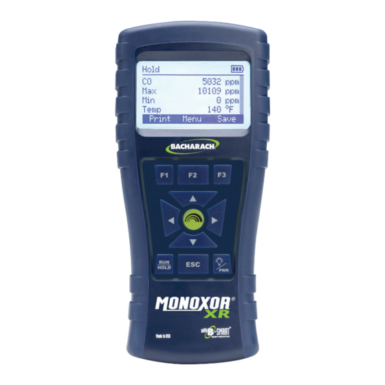
Monoxor XR User Manual ® 4.4 The RUN and Hold Screens Menus and the items contained within them are described in a top-down fashion, starting from the startup screens and working sequentially through the menus and menu items. Fig. 4-3: Sample RUN and Hold Screens Sample Run/Hold Screen Ba ery Status Icon 0 ppm... -
Page 41: Co Trending Graph
Monoxor XR User Manual ® NOTE: Use the left or right arrow buttons from the Run or Hold screen to view the CO trending graph. 4.5 CO Trending Graph A trending screen is accessible from the RUN or HOLD screen by using the right of left arrow keys. -
Page 42: Ending A Test
Monoxor XR User Manual ® 4.6 Ending a Test WARNING: Burn Hazard. Do not touch the probe after removing it from a flue. Allow the probe to cool before handling (about 5 minutes). After taking a gas sample, remove the probe and take the analyzer to an area containing fresh air. -
Page 43: Timed Ambient Co Testing
Monoxor XR User Manual ® 5. After a T2 temperature reading is displayed and stabilizes, press the F3 (SAVE) button to store the current T2 temperature reading. 6. The temperature differential temperature (T1-T2) will be displayed. Figure 4-7: Diff Temp Menu 7. -
Page 44: Printing Using The Optional Irda Printer
Monoxor XR User Manual ® 4.9 Printing Using the Optional IrDA Printer The instrument has the ability to store, recall (to the display), and print sets of time- and date- coded test records. The time and date are set through software menu selections. •... - Page 45 Monoxor XR User Manual ® Figure 4-9: Using Optional IrDA Printer IR Communication Settings: Baud Rate: 9600 Data Bits: Stop Bits: Parity: None Protocol: IRDA-SIR Distance: 8 - 16 in (20 - 41 cm) Angle: 60° maximum 0019-9376 Revision 0...
-
Page 46: Turning Off The Analyzer
Monoxor XR User Manual ® The Monoxor XR provides three lines of 20 characters for user information. This information ® will appear with test records when they are printed. User name and optional information are entered via software menu selections in the SETUP MENU or via the Fyrite User Software (FUS). -
Page 47: Pc Interface And Fyrite ® User Software
Monoxor XR User Manual ® 4.11 PC Interface and Fyrite User Software ® A PC with Fyrite User Software (FUS) installed can set, edit, and transfer the following: ® • Instrument time and date • Calibration password • Time meters •... -
Page 48: Care & Maintenance
Monoxor XR User Manual ® 5. Care & Maintenance Serviceability ........................50 Cleaning the Probe ......................51 5.2.1 Equipment Required ..........................51 5.2.2 Procedure ..............................52 Filter Replacement ......................53 CO Sensor Replacement ....................54 5.4.1 Accessing the CO Sensor ..........................54 5.4.2 Material Required (As Needed) .........................54 5.4.3 CO Sensor Replacement Procedure ......................55... -
Page 49: Cleaning The Probe
Monoxor XR User Manual ® 5.2 Cleaning the Probe The probe tube and gas sample hose will become dirty under normal use. NOTE: The filter element should prevent soot from reaching the analyzer’s internal components. If the probe is not kept clean, it could become clogged and restrict the flow of gas into the analyzer, resulting in incorrect test readings. -
Page 50: Procedure
Monoxor XR User Manual ® 5.2.2 Procedure 1. Remove gas sample hose from the disposable filter assembly. CAUTION: Carburetor cleaner damages plastic components. Take precautions not to spray cleaner onto the probe handle or analyzer. 2. Insert the plastic spray tube of the carburetor cleaner into the gas sample hose, and then liberally spray carburetor cleaner through the hose and out the probe tube. -
Page 51: Filter Replacement
Monoxor XR User Manual ® 5.3 Filter Replacement Figure 5-1: Filter Replacement 0019-9376 Revision 0... -
Page 52: Co Sensor Replacement
Monoxor XR User Manual ® 5.4 CO Sensor Replacement 5.4.1 Accessing the CO Sensor Figure 5-2: Accessing the CO Sensor 0019-9376 Revision 0... -
Page 53: Co Sensor Replacement Procedure
Monoxor XR User Manual ® 5.4.1 CO Sensor Replacement Procedure Follow the procedure below for CO sensor replacement. 1. Remove battery door and the connector tubing from the CO sensor. 2. Remove CO cap by twisting counter clockwise. 3. Gently pull CO sensor out of its socket. 4. -
Page 54: B-Smart ® Co Sensor Replacement
CALIBRATION MENU. If an incorrect code was entered, the screen will display “Invalid Code.” Check to make sure the correct code has been entered If the problem persists, contact your nearest Bacharach Service Provider. NOTE: B-Smart codes can be entered through the Fyrite User Software (FUS) ®... -
Page 55: Temperature Calibration
Monoxor XR User Manual ® 5.5 Temperature Calibration This procedure first zeroes and then spans the temperature channel to known temperature values. The use of an electronic thermocouple simulator is the preferred method of producing the desired calibration temperatures. Alternatively, ice and boiling water baths can be used. 5.5.1 Materials Required •... - Page 56 Monoxor XR User Manual ® 4. Set thermocouple simulator to 32° F (0° C), and then use the UP ( ) and DOWN ( ), LEFT ( ) and RIGHT ( ) arrow buttons to enter an Applied value that exactly equals the setting of the simulator.
-
Page 57: Co Sensor Calibration
Monoxor XR User Manual ® 5.6 CO Sensor Calibration 5.6.1 Materials Required • Calibration kit, P/N 0024-7059 • Gas cylinder: 500 ppm CO in air, P/N 0024-0492 5.6.2 CO Manual Zero Procedure The CO zeroing process is done automatically during warm-up or manually using the manual zero feature. -
Page 58: Co Sensor Span Procedure
2. Use the UP ( ) and DOWN ( ), LEFT ( ) and RIGHT ( ) arrow buttons to enter an Applied value that exactly equals the concentration stamped on the CO cylinder. NOTE: Bacharach recommends using a 500 ppm calibration gas, however the calibration range is from 100 - 5,000 ppm. An attempt to calibrate outside this range will cause the message “Applied Value High”... -
Page 59: T-Ref Sensor Calibration
Monoxor XR User Manual ® If the sensor’s output is low, but still usable, then the message “Good Calibration WARNING Low Sensor” will appear. The sensor will now be marked as being Low in the Warm-up screen. If the sensor’s output is too low to be usable, then the message “Bad Calibration Sensor End of Life, Entry Not Saved”... -
Page 60: Troubleshooting
Monoxor XR User Manual ® 6. Troubleshooting Error and Warning Messages ..................62 Replacement Parts......................63 Accessories ........................63 6.4 Instrument Identification ..................... 64 6.1 Error and Warning Messages Message Description Low Sensor CO CO sensor output was low but still usable. Sensor may need to be replaced in the near future. -
Page 61: Replacement Parts
Monoxor XR User Manual ® 6.2 Replacement Parts Part Number Description 0204-0004 Battery, AA Alkaline (qty 1) 0024-0997 CO sensor, uncalibrated 0024-1795 B-Smart CO sensor ® 0019-7110 Replacement probe assembly with water trap 0019-3265 Replacement water trap for probe assembly 0024-7110 0 0 0 7 - 1 6 4 4 Replacement filter element for probe assembly 0024-7110 0 0 2 4 - 1 5 7 9... -
Page 62: Instrument Identification
Monoxor XR User Manual ® 6.4 Instrument Identification A label on the back of the instrument provides the following information that is useful for service and troubleshooting. • manufacturer • country of origin • certification(s) • part number • serial number Figure 6-1: Identification Label 0019-9376 Revision 0... -
Page 63: Additional Information
Android: (for the application only) Hard Drive Space iOS: (for the application only) 7.2 Service Centers Replacement parts and service can be obtained by contacting one of the following Bacharach Service Centers. Location Contect Information Shipping Address Phone: +1 724 334 5000 Bacharach, Inc. - Page 64 Bacharach, Inc. 621 Hunt Valley Circle, New Kensington, PA 15068 USA Pittsburgh, PA USA | Dublin, IRE | Stanardsville, VA USA | Toronto, CAN www.mybacharach.com | help@mybacharach.com...
Need help?
Do you have a question about the Monoxor XR and is the answer not in the manual?
Questions and answers