Bacharach MGD-100 Quick Installation Manual
Gas detector and controller
Hide thumbs
Also See for MGD-100:
- Installation and operation manual (48 pages) ,
- Installation and operation manual (44 pages)
Advertisement
GAS DETECTOR and CONTROLLER
QUICK INSTALLATION GUIDE
P/N: 6109-9002
Revision 0
January 13, 2016
IP41 Sensor
1-2 Sensor
Controller Housing
CAUTION: DO NOT MOUNT the
MGD-100 in an area that may
contain flammable liquids or
vapors. Operation of electrical
equipment in such an area consti-
tutes a safety hazard.
WARNING: Strictly follow the
instructions in the User Manual
(part number 6109-9000) available
at www.MyBacharach.com.
1: OPERATING AREA AND CONDITIONS
The Bacharach MGD-100 is an instrument for the
continuous monitoring of refrigerant, combustible,
and toxic gases. The system is available with one or
two levels of alarm, and consists of 1 to 6 remote gas
sensors connected to and powered by a controller.
The controller is powered by 12 VDC or 100-230 VAC
50-60 Hz (specified at time of order).
2: SAFETY INSTRUCTIONS
USER MANUAL: Before using this equipment,
carefully read and strictly follow the User Manual
(part number 6109-9000). The user must fully
understand and strictly observe the instructions.
Use the equipment only for the purposes listed and
under the conditions specified in that document.
CODE COMPLIANCE: Comply with all local and
national laws, rules and regulations associated with
this equipment.
GENUINE PARTS: Use only genuine Bacharach spare
parts and accessories, otherwise proper functioning
of the equipment may be impaired.
TECHNICIAN USE ONLY: This unit must be installed
by a suitably qualified technician who will install this
unit in accordance with these instructions and the
standards in their particular industry/country. Opera-
tors of the unit should be aware of the regulations
and standards in their industry/country for the
operation of this unit. These notes are only intended
as a guide and the manufacturer bears no responsi-
bility for the installation or operation of this unit.
Standard
Failure to install and operate the unit in accordance
Housing
with these instructions and with industry guidelines
may cause serious injury including death and the
manufacturer will not be held responsible in this
regard.
SAFE MOUNTING: This monitor must be connected
by a marked, suitably located and easily reached
switch or circuit-breaker as means of disconnection.
3: WEIGHTS AND DIMENSIONS
Type/Enclosure
Dimensions
3.35" x 5.59" x 2.09"
IP41
86 x 142 x 53 mm
6.89" x 6.5" x 3.29"
IP66
175 x 165 x 82 mm
6.89" x 8.9" x 3.29"
IP66 w/ Splash
Guard
175 x 225 x 82 mm
6.89" x 6.1" x 3.29"
IP66 w/ Remote
Sensor
175 x 155 x 82 mm
6.89" x 6.1" x 3.29"
IP66 w/ Ex d
Remote Head
175 x 155 x 82 mm
6.89" x 6.1" x 3.29"
IP66 w/ PRV
Sensor Head
175 x 155 x 82 mm
6.89" x 4.9" x 3.29"
IP66 Airflow/
Duct (See Table)
175 x 125 x 82 mm
5.12" x 6.3" x 3.54"
Ex d (Enclosure)
130 x 160 x 90 mm
Supported CFM & Duct Sizes for Duct Mount Housing
Duct Size
Units
Inches
12 x 12
12 x 24
18 x 18
Feet
1 x 1
1 x 2
1.5 x 1.5
Area (ft
2
)
1
2
2.25
4: MOUNTING
ENVIRONMENTAL CONSIDERATIONS: Care-
fully consider the full range of environmental
conditions to which the instruments will be
exposed.
TARGET GAS CONSIDERATIONS: The physical
data of the gas or vapor to be detected must
be observed.
APPLICATION CONSIDERATIONS: The specifics
of the application (for example, possible leaks,
air movement/draft, etc.) must be observed.
ACCESSIBILITY CONSIDERATIONS: The degree
of accessibility required for maintenance
purposes must be granted.
ACCESSORY CONSIDERATIONS: The types of
optional and accessory equipment that will be
used with the system must be kept in mind.
ELECTRONIC CONSIDERATIONS: The system
contains sensitive electronic components that
can be easily damaged. Do not touch nor
disturb any of these components.
Mount the MGD-100 and Controller according
to the above considerations, product dimen-
sions (see Section 3), maximum wiring lengths
(see Section 5), and the corresponding mount-
ing dimensions shown in the illustrations that
follow.
Ex d Housing
3.5 in
(90 mm)
Weights
6.3 oz
180 g
1 lb 6 oz
629 g
1 lb 9 oz
700 g
1 lb 11 oz
790 g
4.8 in
2 lb 10 oz
(122 mm)
1185 g
2 lb 0.3 oz
916 g
1 lb 4 oz
578 g
9 lb 4 oz
4200 g
1.7 in
(42 mm)
mounting slots =
0.35 in (9mm) long x
24 x 24
24 round
2.3 in
0.24 in (6mm) wide
(59 mm)
Use 3/16-inch screws
2 x 2
Pi x 1 x 1
(5mm - 6mm )
4
3.14
5.7 in
(146 mm)
3.39 in (86.0 mm)
0.28 in
(7.0 mm)
1.69 in (43.0 mm)
�
018 in
(4.50 mm)
(36.00 mm)
0.31 in
(8.0 mm)
1.0 in
(25.00 mm)
Screw
0.2 in
(5.0 mm)
5.1 in
(130 mm)
0.6 in
(15.0 mm)
0.5 in (12.7 mm)
IP66 Housing
PRV/IP66
Vent Pipe
Monitoring 1
Exd Remote
in BSP Head
Head
M42 thread
1"BSP thread
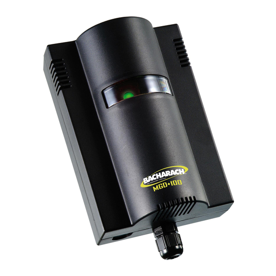
Standard
IP41 Housing
�
0.18 in
(4.50 mm)
2.09 in (53 mm)
�
0.35 in
(9.0 mm)
1.4 in
1.0 in
(25.00 mm)
0.4 in (9.0 mm)
0.6 in
(15.5 mm)
2.0 in
(50.0 mm)
0.4 in (10.0 mm)
1-2 Sensor
Controller
Housing
Screw
0.2 in
(4.8 mm)
0.6 in (15.0 mm)
2.9 in (74.5 mm)
0.5 in (12.7 mm)
10.26 in (260.50mm)
5.13 in (130.25 mm)
O 0.20 in (5.10 mm)
Mounting
Hole
4-6 Sensor
Controller Housing
O 0.18 in (4.60 mm)
9.55 in (242.50 mm)
Advertisement
Table of Contents

Related Manuals for Bacharach MGD-100


Summary of Contents for Bacharach MGD-100
- Page 1 Monitoring 1 130 x 160 x 90 mm 4200 g Exd Remote 4-6 Sensor The Bacharach MGD-100 is an instrument for the in BSP Head Head Controller Housing continuous monitoring of refrigerant, combustible, Supported CFM & Duct Sizes for Duct Mount Housing and toxic gases.
- Page 2 PG7 openings for Relay 2 High Alarm Relay SENSOR 2 Relay RESET cable glands or plugs. Each MGD-100 IP41 transmit- FAIL (Volt Free) SENSOR 2 ter will have a single opening for an M20 cable SAFE FAIL...
Need help?
Do you have a question about the MGD-100 and is the answer not in the manual?
Questions and answers