ADTRAN Total Access 1248 Installation And Maintenance Practice
Expansion dslam
Hide thumbs
Also See for Total Access 1248:
- Installation and maintenance practice (234 pages) ,
- Specifications (2 pages)

Related Manuals for ADTRAN Total Access 1248


Summary of Contents for ADTRAN Total Access 1248
- Page 1 ® Total Access 1248 Expansion DSLAM Installation and Maintenance Practice Document Number: 61179641L5-5C CLEI Number: VAMBH00A_ _ September 2007...
- Page 2 In no event will ADTRAN be liable for any special, incidental, or consequential damages or for commercial losses even if ADTRAN has been advised thereof as a result of issue of this document.
- Page 3 Revision History Revision Date Description October 2004 Initial release September This is the second release of this document. This revision includes 2005 an update to software version B02 and an update to the document format. September This is the third release of this document. This revision includes an 2007 update to software version B03.06.01.
- Page 4 Total Access 1248 Expansion DSLAM Installation and Maintenance Practice Training ADTRAN offers training courses on our products. These courses include overviews on product features and functions while covering applications of ADTRAN product lines. ADTRAN provides a variety of training options, including customized training and courses taught at our facilities or at customer sites.
-
Page 5: Table Of Contents
Mounting the Total Access 1248 ........ - Page 6 Logging on to the Total Access 1248 ........
- Page 7 ADTRAN Technical Support ........
- Page 8 Figure 3-7. Total Access 1248 POTS and ADSL+POTS Connections ......3-10 Figure 3-8.
- Page 9 Total Access 1248 Shipping Contents ........
- Page 10 Total Access 1248 Expansion DSLAM Installation and Maintenance Practice This page is intentionally blank. 61179641L5-5C...
-
Page 11: Introduction
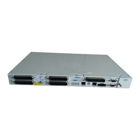
Section 1 Introduction GENERAL The Total Access 1248 (see Figure 1-1) is a Digital Subscriber Line Access Multiplexer (DSLAM) system that is used to further extend Asymmetrical Digital Subscriber Line (ADSL) services in the network. FAN MODULE 1179675L1 1179641L5 -48V RET -48V RET... -
Page 12: Description
Total Access 3000 IMA Aggregation System • Compliant with GR-63-CORE/GR-1089-CORE (NEBS), and Listed to the applicable UL Safety Standard(s) • Expansion capabilities for a total of three Total Access 1248 Client chassis to a Host unit • In-band management of the expansion chassis 61179641L5-5C... -
Page 13: Front Panel Leds
Description Front Panel LEDs There are six LEDs on the front panel of the Total Access 1248, as shown in Figure 1-2. • Two LEDs provide status information ( • Two LEDs provide Expansion Port input ( ) status EXPANSION IN •... -
Page 14: Compliance
The Total Access 1248 is NRTL listed to the applicable UL standards. The Total Access 1248 meets or exceeds all the applicable requirements of NEBS, Telcordia GR-63-CORE, and GR-1089-CORE. - Page 15 Per GR-1089-CORE the Total Access 1248 is designed and intended for installation as part of a Common Bonding Network (CBN). The Total Access 1248 is not designed nor intended for installation as part of an Isolated Bonding Network (IBN). CAUTION...
- Page 16 Total Access 1248 Expansion DSLAM Installation and Maintenance Practice This page is intentionally blank. 61179641L5-5C...
-
Page 17: Application Guidelines
Section 2 Application Guidelines INTRODUCTION The Total Access 1248 provides 48 ADSL2+ plus POTS ports downstream to the subscriber, local and remote management capabilities, and front panel LEDs that indicate status. Figure illustrates an operational scenario for the Total Access 1248. -
Page 18: Expansion
Figure 2-2). One of the units must be a Total Access 1248 Host unit (e.g., P/N 1179641L4) and the others are Total Access 1248 Client units (P/N 1179641L5). The client units (also referred to as Expansion units) have RJ-45 jacks, labeled EXPANSION IN , for the purpose of expanding one to another. -
Page 19: Installation
After unpacking the Total Access 1248, inspect it for damage. If damage has occurred, file a claim with the carrier and then contact ADTRAN Customer Service. Refer to “Appendix A,... -
Page 20: Shipping Contents
Total Access 1248 Expansion DSLAM Installation and Maintenance Practice Shipping Contents The shipping container for the Total Access 1248 includes the contents shown in Table 3-1. Table 3-1. Total Access 1248 Shipping Contents Description Part Number Quantity Total Access 1248 Expansion DSLAM... -
Page 21: Installation Prerequisites
ADTRAN recommends an external fuse rated at 3.0 amps. INSTALLATION STEPS The following steps are required to install the Total Access 1248. Each step has an associated procedure which is referenced below the step. Each procedure provides detailed information for completing the step. -
Page 22: Mounting The Total Access 1248
Total Access 1248 Expansion DSLAM Installation and Maintenance Practice Mounting the Total Access 1248 The Total Access 1248 is shipped with two sets of mounting brackets that accommodate either a 19-inch or 23-inch rack. • The mounting brackets used for a 19-inch rack are part number 3265540. -
Page 23: Flush-Mount
Installation Steps Flush-mount For flush-mount systems, the Total Access 1248 must be mounted from the front of the rack, with mounting brackets in the flush-mounting orientation (see Figure 3-2). When flush- mounting a Total Access 1248 in the rack, use a #2 phillips-head screwdriver and attach the mounting brackets, with the flanges containing the slotted rack-mounting holes facing the front, to the mounting bracket holes closest to the front of the Total Access 1248. -
Page 24: Mid-Mount
Total Access 1248 Expansion DSLAM Installation and Maintenance Practice Mid-mount For mid-mount systems, the Total Access 1248 must be mounted from the rear of the rack, with mounting brackets in the mid-mounting orientation (see Figure 3-3). For mid-mounting a Total Access 1248 in the rack, use a #2 phillips-head screwdriver and attach the mounting brackets, with the flanges containing the slotted rack-mounting holes facing the front, to the mounting bracket holes closest to the back of the Total Access 1248. -
Page 25: Ground Connection
The ground wire must be 12 to 18 AWG, however, it must be as large or larger than the wire used for power. The Total Access 1248 must be grounded to a reliable grounding source. To connect the ground wire, perform the following steps: 1. -
Page 26: Power Connection
4. While holding the wire in place, tighten the setscrew until the wire is secure. 5. Repeat steps until all power leads are connected. 6. Apply power to the Total Access 1248 and test the voltage and polarity on the terminal block using the tops of the setscrews as test points. 61179641L5-5C... -
Page 27: Fans/Fan Filter
Figure 3-6). The fans move filtered air (if the filter is installed) into the Total Access 1248 chassis and out through the exhaust slots on the left side. The fans are monitored by the system and are tested during power-up or when a fan module is installed. -
Page 28: Adsl2+ Plus Pots Connections
Figure 3-7. Total Access 1248 POTS and ADSL+POTS Connections POTS Interface Each POTS interface on the Total Access 1248 accepts a POTS signal from the Central Office (CO) and passes it through to the ADSL2+ plus POTS interface for delivery to the subscriber. -
Page 29: Pots Connection
Installation Steps POTS Connection The Total Access 1248 must be connected to a POTS source to provide POTS to the subscribers. In a standard configuration, the POTS will be brought in from a nearby cross- connect. The Total Access 1248 accepts the POTS signal on the top two amphenol connectors labeled . -
Page 30: Table 3-2. Pots And Adsl+Pots Cable Pin Assignments For Left-Most Connectors
Total Access 1248 Expansion DSLAM Installation and Maintenance Practice Table 3-2. POTS and ADSL+POTS Cable Pin Assignments for Left-most Connectors Pair # Pins R.T. Pair # Pins R.T. 1, 26 13, 38 2, 27 14, 39 3, 28 15, 40... -
Page 31: Total Access 1200F Conversion
Total Access 1200F Conversion TOTAL ACCESS 1200F CONVERSION CAUTION The order of subtended Total Access 1200 Series DSLAMS must be preserved when connecting to the Total Access 1200F for transla- tion to the legacy ATM mode PVCs. See Table 3-4. Table 3-4. - Page 32 Total Access 1248 Expansion DSLAM Installation and Maintenance Practice 3. Press and hold the key on the terminal keyboard and apply power to the Total Access 1200 Series DSLAM. 4. When prompted, select 38400 for a faster transfer rate (20 minutes at 38400 compared to 60 minutes at 9600).
-
Page 33: Provisioning Defaults
Section 4 Provisioning Defaults INTRODUCTION The Total Access 1248 system default provisioning options are shown in Table 4-1. For T1, IMA, SNMP, and ATM provisioning, refer to the Installation and Maintenance Practice for the host Total Access 1248 system. For detailed information on the Total Access 1248 menus, refer to “Section 5, User... - Page 34 Total Access 1248 Expansion DSLAM Installation and Maintenance Practice This page is intentionally blank. 61179641L5-5C...
-
Page 35: User Interface
5-8 SYSTEM MANAGEMENT Total Access 1248 system management and provisioning is facilitated by a series of intuitive menus that are accessible on a computer screen. The Total Access 1248 provides two methods for management access: • “Craft Interface”... -
Page 36: Inband Management Interface
2. Set the PC for direct connect on the appropriate communications port (as opposed to dial up connection). 3. Plug the male end of the data cable into the Total Access 1248. Make connection to the PC or laptop as appropriate for the equipment. -
Page 37: Logging On To The Total Access 1248
Logging on to the Total Access 1248 LOGGING ON TO THE TOTAL ACCESS 1248 To logon to the Total Access 1248 system, perform the following steps: 1. Establish the physical connection to the Total Access 1248. 2. If a craft port session is being used, proceed to step 3. If using a Telnet session proceed to step 4. -
Page 38: Menu Structure
Total Access 1248 Expansion DSLAM Installation and Maintenance Practice MENU STRUCTURE The menu structure for the Total Access 1248 is a layered menu tree. Each layer of the menu tree is displayed as a menu or a screen. Menu A menu is a display that provides numbered selections that are used to navigate to related menus, modify provisioning information, or display information screens. -
Page 39: Menu Navigation
Table 5-1 shows the general keyboard commands, and Table 5-2 shows the menu specific hot keys for the Total Access 1248 system. Table 5-1. General Keyboard Commands Keyboard Command Description This keyboard command is used to delete the character to the left of ACKSPACE the cursor during keyboard input. - Page 40 Total Access 1248 Expansion DSLAM Installation and Maintenance Practice Table 5-2. Menu Specific Hot Keys (Continued) Hot Key Description This hot key is used to display the last page of events. This hot key is used to display the next page of events.
-
Page 41: Menu Tree
Menu Tree MENU TREE There are a number of menu screens designed to aid in the maintenance and troubleshooting of the Total Access 1248 system. The Total Access 1248 system menu tree (see Figure 5-3) is a visual map that can be used to locate configuration information and provisioning options. -
Page 42: Menu Descriptions
6. System Event Log 7. Contact Information 8. Enter TL1 mode 9. Logoff Selection : '?' - System Help Screen Figure 5-4. Total Access 1248 Main Menu The Total Access 1248 Main menu options are shown in Table 5-3. 61179641L5-5C... -
Page 43: Table 5-3. Total Access 1248 Main Menu Options
This option displays the “Configuration Screen” page 5-10. ATM Circuit Management ATM circuits cannot be viewed from a client shelf. Logon to the Total Access 1248 host unit to view this data. System Management This option displays the “System Management Menu” page 5-11. -
Page 44: Configuration Screen
5-5) displays information about the system. For instance, the CLEI Code and Part Number can be used to search for related information on the ADTRAN web site or to order additional parts. The software revision can be required when calling the ADTRAN Technical Support. -
Page 45: System Management Menu
System Management Main Menu\System Management\ The System Management menu (Figure 5-6) is used to manage system settings. The following subsections describe these settings in detail. Total Access 1248 MM/DD/YY HH:MM Unacknowledged Alarms: None System Management 1. Password Control 2. Baud Rate 3. - Page 46 Total Access 1248 Expansion DSLAM Installation and Maintenance Practice Table 5-5. System Management Menu Options (Continued) Option Description Function Reset System This option displays the “Reset System Menu” page 5-21. Self Test Results This option displays the “Self Test Screen”...
-
Page 47: Password Control Menu
The Password Control menu (Figure 5-7) is used to set and modify passwords, logout times, and restore default passwords. The system provides up to eleven user accounts. Total Access 1248 Unacknowledged Alarms: None Password Control 1. Set Passwords None Configured 2. -
Page 48: Password Control Levels Screen
Total Access 1248 Expansion DSLAM Installation and Maintenance Practice Password Control Levels Screen Password Control Levels Main Menu\System Management\Password Control\Password Control Levels\ The Password Control Levels screen (see Figure 5-8) is used to manage the usernames and associated passwords that access the system. -
Page 49: Allow Snmp Security Management
Menu Descriptions 5. Enter the password again when prompted to verify, and press E NTER 6. Press the T key to navigate to the Access Level field. The Access Level field displays is reverse video. 7. Press the spacebar to change the access level, and press E NTER 8. -
Page 50: Current Baud Rate Menu
Total Access 1248 Expansion DSLAM Installation and Maintenance Practice Current Baud Rate Menu Current Baud Rate Main Menu\System Management\Current Baud Rate\ The Current Baud Rate menu (see Figure 5-9) displays the current baud rate. The default management port baud rate is 9600 bps. -
Page 51: Expansion Menu
The Expansion Menu (Figure 5-10) is used to enable or disable expansion capabilities for up to four Total Access 1248 units (one host and three clients). The expansion mode should only be enabled on the host units. Total Access 1248... -
Page 52: Download New Code Menu
Total Access 1248 Expansion DSLAM Installation and Maintenance Practice Download New Code Menu Download New Code Main Menu\System Management\Download New Code\ The Download New Code menu displays one method to download code: • Y-Modem CAUTION Downloading new code is service affecting. - Page 53 Menu Descriptions To download code via the Y-Modem menu, perform the following steps: 1. Access the system with System Administrator privileges using a terminal application that allows file transfers, such as HyperTerminal. 2. From the Y-Modem menu, select , and press E Download Network Module Code NTER The Y-Modem receive utility begins.
-
Page 54: Restore Factory Defaults Menu
Total Access 1248 Expansion DSLAM Installation and Maintenance Practice Restore Factory Defaults Menu Restore Factory Defaults Main Menu\System Management\Restore Factory Defaults\ The Restore Factory Defaults menu (see Figure 5-12) is used to remotely restore the system to factory defaults. CAUTION This action is service affecting. -
Page 55: Reset System Menu
5-12. Table 5-12. Reset System Menu Options Option Description Function Reset This option reboots the Total Access 1248. All system options are retained. Exit This option returns the display to the “System Management Menu” on page 5-11. The system does not reboot. -
Page 56: Self Test Screen
The Self Test screen (see Figure 5-14) displays ROM, RAM, and EEPROM test results after a reboot of the Total Access 1248 system. If any tests result in a failed status, the word “Failed” displays next to that test and the LED turns red. -
Page 57: Dsl Menus
ADSL Status This option is not accessible on the Total Access 1248 client. Logon to the Total Access 1248 host unit to view this information. ADSL Performance This option is not accessible on the Total Access 1248 client. -
Page 58: System Alarm Log Screen
System Alarm Log Screen System Alarm Log Main Menu\System Alarm Log\ The Total Access 1248 system provides a system alarm log for monitoring alarms. To view the System Alarm Log screen (Figure 5-16), select m the Main menu, and press... -
Page 59: System Event Log Screen
System Event Log Screen System Event Log Main Menu\System Event Log\ The System Event Log screen (see Figure 5-17) provides non-volatile storage of system events. Total Access 1248 MM/DD/YY HH:MM Unacknowledged Alarms: None System Event Log Events: 1 to 10 of... -
Page 60: Contact Information Screen
Total Access 1248 Expansion DSLAM Installation and Maintenance Practice Contact Information Screen Contact Information Main Menu\Contact Information\ The Contact Information screen (Figure 5-18) displays ADTRAN technical support, repair, and online support contact information. Total Access 1248 MM/DD/YY HH:MM Unacknowledged Alarms: None... -
Page 61: Tl1 Mode Screen
Figure 5-19. TL1 Mode Screen Table 5-16 lists the TL1 commands supported by the Total Access 1248 system. For further details of the TL1 commands, refer to the Total Access 11xx and 12xx ADSL2+ DSLAM TL1 Command Reference Guide (P/N 61179611L1-35). -
Page 62: Table 5-16. Tl1 Commands
Total Access 1248 Expansion DSLAM Installation and Maintenance Practice Table 5-16. TL1 Commands TL1 Commands ACT-PROFILE-ADSL ENT-T1 RTRV-CRS-VC ACT-USER ENT-VCL RTRV-EQPT ALW-MSG-ADSL GET-SYS-INFO RTRV-HDR ALW-MSG-T1 INH-MSG-ADSL RTRV-INV-EQPT ALW-MSG-EQPT INH-MSG-T1 RTRV-IPPORT ALW-MSG-ENV INH-MSG-EQPT RTRV-NE-ALL ALW-MSG-ALL INH-MSG-ENV RTRV-PM-T1 CANC-USER INH-MSG-ALL RTRV-PROFILE-ADSL DLT-ADSL... -
Page 63: Maintenance
Warranty”. Fan Modules Four fans are installed in the Total Access 1248 in a removable module to maintain the hardware within proper operating temperature tolerances. With the exception of the filter, the fan module is not field serviceable. The fan module (P/N 1179675L1) is field replaceable and is available from ADTRAN. -
Page 64: Fan Filters
2. Tighten the screw that holds the fan module in place. Fan Filters The Total Access 1248 Expansion DSLAM fan module comes with a single fan filter. The filter is designed to remove particles from the air before it is pushed through the system. -
Page 65: Table 7-1. Total Access 1248 Specifications
Section 7 Specifications INTRODUCTION Specifications for the Total Access 1248 are detailed in Table 7-1. Table 7-1. Total Access 1248 Specifications Specifications Descriptions ADSL Loop Interface Modulation Type: Discrete Multi-Tone (DMT) Mode: Full Duplex, Non-overlapped Standards: T1.413; G.992.1 Annex A; G.992.2 Annex A, G.992.3, G.992.4, G.992.5... - Page 66 Total Access 1248 Expansion DSLAM Installation and Maintenance Practice Table 7-1. Total Access 1248 Specifications (Continued) Specifications Descriptions Environment Temperature: Operating (Standard): –40°C to +70°C Storage: –40°C to +85°C Humidity: 95% non-condensing Part Numbers Total Access 1248 Expansion DSLAM: 1179642L1...
- Page 67 Appendix A Warranty WARRANTY AND CUSTOMER SERVICE ADTRAN will replace or repair this product within the warranty period if it does not meet its published specifications or fails while in service. Warranty information can be found at www.adtran.com/warranty. Refer to the following subsections for sales, support, Customer and Product Service (CAPS) requests, or further information.
- Page 68 ® Carrier Networks Division 901 Explorer Blvd. Huntsville, AL 35806...
Need help?
Do you have a question about the Total Access 1248 and is the answer not in the manual?
Questions and answers