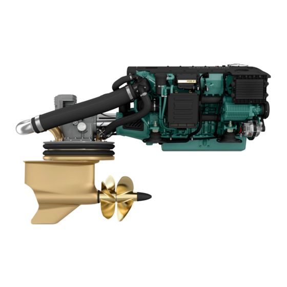
Volvo Penta IPS Installation And System Connections
Autopilot system dpu
Hide thumbs
Also See for IPS:
- Operator's manual (124 pages) ,
- User manual (140 pages) ,
- Operator's manual (158 pages)
Summary of Contents for Volvo Penta IPS
- Page 1 87054_2.book Page 1 Friday, July 22, 2005 10:56 AM Volvo Penta IPS Autopilot System DPU Installation and System Connections Document Number: 87054-2 Date: July 2005...
-
Page 2: Handbook Information
87054_2.book Page 2 Friday, July 22, 2005 10:56 AM Volvo Penta IPS Autopilot System Handbook information To the best of our knowledge, the information in this handbook was correct when it went to press. However, Raymarine cannot accept liability for any inaccuracies or omissions it may contain. -
Page 3: Installation Procedures
SmartController can be fitted as optional extras. This handbook will guide you through the installation of your IPS DPU and the connections that you will need to make to the other parts of the IPS system. Volvo Penta IPS System - Top Level Schematic... -
Page 4: Parts Supplied
D8035-2 Additional parts required To complete the installation you will also require the Autopilot Interface kit from Volvo Penta. Part Number 3819744, comprising of a Gateway, Y-split, Assembly instruction and tie-wraps. Autopilot Interface Kit - Volvo Penta part number 3819744... -
Page 5: Emc Installation Guidelines
87054_2.book Page 5 Friday, July 22, 2005 10:56 AM 1.3 Planning the installation Important Safety Information WARNING: Product installation This equipment must be installed and operated in accordance with the Raymarine instructions provided. Failure to do so could result in poor product performance, personal injury and/or damage to your boat. -
Page 6: Control Head
Volvo Penta IPS Autopilot System 1.4 S3G Course Computer Please refer to the SmartPilot Commissioning Guide for detailed installation instructions for the IPS S3G and fluxgate compass. 1.5 Control Head Please refer to the Control Head installation sheet for detailed installation instructions. - Page 7 87054_2.book Page 7 Friday, July 22, 2005 10:56 AM 1. Remove the outer cover. D5794-1 2. Place the DPU in the required position and mark the position of the fixing holes. 3. Using a 1/8 in (3.5 mm) drill, drill a pilot hole for each of the two fixing screws. 4.
-
Page 8: Identifying Cables
87054_2.book Page 8 Friday, July 22, 2005 10:56 AM Volvo Penta IPS Autopilot System 1.7 Running SeaTalk & NMEA2000 cables Cable routing practices When running cable, always observe the following guidelines: • If a cable has to be fed through the deck, always use a good quality deck gland. -
Page 9: System Power
DO NOT CONNECT ANY OTHER POWER SOURCE TO THE DPU. 1.9 Cable preparation In an IPS system, cables not already fitted with molded connectors must be correctly prepared for connection. The DPU uses color-coded, spring retention connectors. To make a secure connection to a spring retention connector, prepare the cable for connection, then use the method illustrated below to connect each wire. -
Page 10: Connections To Dpu
87054_2.book Page 10 Friday, July 22, 2005 10:56 AM Volvo Penta IPS Autopilot System D5907-1 1.10 Connections to DPU The diagram below illustrates the connections that are required to and from the DPU. Ferrites Ensure that all cables connected to the DPU have a clip-on ferrite fitted. - Page 11 87054_2.book Page 11 Friday, July 22, 2005 10:56 AM SeaTalk Connector Block 1 2 3 4 5 to Volvo Penta Autopilot Interface Unit Yellow grounding cable NMEA 2000 RF ground S3G Course Computer Terminals SeaTalk SeaTalk NMEA 0183 D8037-2 SeaTalk Using the appropriate cable, connect the SeaTalk terminal on the DPU to one of the SeaTalk terminals on the S3G Autopilot.
-
Page 12: Additional Connections
87054_2.book Page 12 Friday, July 22, 2005 10:56 AM Volvo Penta IPS Autopilot System NMEA 0183 Connect the NMEA 0183 terminal on the DPU to the NMEA 1 terminal on the S3G course computer. Ensure that the following connectivity is achieved:... - Page 13 Consult your Volvo Penta dealer before making any changes to your existing system. To connect to the Volvo Penta system you will need to obtain an Autopilot Interface Note: kit from Volvo Penta. Part Number 3819744, comprising of a Gateway, Y-split, Assembly instruction and two tie-wraps.
-
Page 14: Emc Conformance
Connect the Y-split cable to the Volvo Penta Gateway. Use the connection that DOES NOT have a yellow “MUTILINK” label. MULTILINK MULTILINK Finally, connect to the Volvo Penta system bus using the “MULTILINK” ends of the Y-split cable. MULTILINK MULTILINK... -
Page 15: Post Installation Checks
Your boat should continue on its current heading. If the control unit reads “NO IPS” then repeat the wiring checks in step 1. 3. Use either the +10 or -10 keys or the rotary control to make a course change. - Page 16 87054_2.book Page 16 Friday, July 22, 2005 10:56 AM Volvo Penta IPS Autopilot System...


Need help?
Do you have a question about the IPS and is the answer not in the manual?
Questions and answers