
Related Manuals for Volvo Penta D5A


Summary of Contents for Volvo Penta D5A
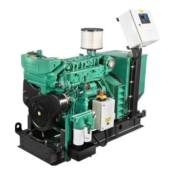
- Page 1 Operator’s manual D5A/7A T/TA Marine Genset Non-Classifiable Control System Control System MCC...
- Page 2 Do not modify or tamper with the exhaust system. • Do not idle the engine except as necessary. For more information www.P65warnings.ca.gov/marine www.p65warnings.ca.gov/products/diesel © 2021 AB VOLVO PENTA Volvo reserves the right to make changes Printed on environmentally friendly paper...
-
Page 3: Table Of Contents
Excessive strain on a product and components ........14 Environmental care ................. 15 Recording engine data ................15 Certified Engines ..................16 Volvo Penta Dealer Network ..............17 Volvo Penta Action Service ..............17 Instruments and Controls ................ 18 Instrument Panel ..................18 Ignition switch .................. - Page 4 Oil Grade and Oil Change Interval ............. 102 Viscosity ..................... 103 Fuel System ..................103 Cooling System ................... 104 Coolant ....................105 Water Quality ..................105 Electrical System ................106 Identification Numbers ............... 107 Index ......................111 47713337 03-2021 © AB VOLVO PENTA...
-
Page 5: Foreword
Pay careful attention to the safety instructions included in the manual. As the owner of a Volvo Penta engine, you become part of a worldwide network of dealers and service workshop that assist you with technical advice, service requirements and replacement parts. -
Page 6: Safety Information
This chapter describes how safety precautions are If anything remains unclear or if you are unsure of presented in the manual and on the product. Read the something, contact your Volvo Penta dealer for chapter through very carefully before you start the assistance. - Page 7 Always wear safety glasses if there is a risk of splintering, sparks and spray from the electrolyte (so- called battery acid), or other chemicals. Your eyes are very delicate and damage can result in loss of sight! 47713337 03-2021 © AB VOLVO PENTA...
- Page 8 Spare parts — safety WARNING! Always use spare parts with the same quality as genuine Volvo Penta parts to minimize the risk of an explosion or fire. Components in fuel systems and electrical systems on Volvo Penta engines are designed and manufactured to minimize the risk of explosions and fire, in accordance with applicable legal requirements.
- Page 9 Information on the engine IMPORTANT: Make sure that all warning and information decals on the product are always visible. Replace decals which have been damaged or painted over. 47713337 03-2021 © AB VOLVO PENTA...
- Page 10 Before welding work IMPORTANT: Before any work with electric weld can begin, the connection to all control units must be disconnected. After finished welding, re-connect the connection to all control units before connecting any battery cable. 47713337 03-2021 © AB VOLVO PENTA...
- Page 11 Smoking is forbidden and the engine must be stopped. Proper fuel quality IMPORTANT: Always use the fuel recommended by Volvo Penta. See Technical Data in Operator’s Manual. Other fuel can damage the engine. Wrong fuel quality can also lead to higher service costs.
- Page 12 If it comes electrolyte to unprotected skin, wash immediately with soap and water. Layout of the battery compartment IMPORTANT: Make sure the battery compartment is designed according to current safety standards. 47713337 03-2021 © AB VOLVO PENTA...
- Page 13 Cleanliness for sensitive components IMPORTANT: Observe meticulous cleanliness when handling system components. Even minimal amounts of dirt could cause a breakdown. Adjustment of the clutch CAUTION! Clutch adjustments must be carried out with the engine stopped. 47713337 03-2021 © AB VOLVO PENTA...
-
Page 14: Introduction
Introduction Check that you heave received the correct operator’s manual before continuing reading. If not, please contact your Volvo Penta dealer. Read the Operator’s Manual carefully and learn to handle the engine, controls and other equipment in a safe manner before you start the engine. -
Page 15: Warranty
Introduction Warranty Your new Volvo Penta marine engine is covered by a limited warranty, subject to the conditions compiled in the Warranty Information. Note that AB Volvo Penta’s liability is limited to the specification in the Warranty Information and Emission Control System Warranty Statement. -
Page 16: Fuel, Oils And Coolant
These qualities will be maintained through regular servicing and the use of spare parts with the same quality as genuine Volvo Penta parts. If reliable and purpose-built parts are not used, your safety, health, and the machine’s function may be compromised. -
Page 17: Environmental Care
Introduction Environmental care Environmental care is a core value at Volvo Penta. Energy efficiency and low emissions are among the most important product related aspects and priority focus areas for Volvo Penta business. Several of the global challenges the world faces are directly or indirectly related to power industries and transports. -
Page 18: Certified Engines
NOTICE! Neglects or failure to follow the points listed here may invalidate the engine emission certificate. This means AB Volvo Penta can no longer guarantee engine conformity with the certified model. Volvo Penta is not responsible for damages or costs arising as a result of this. -
Page 19: Volvo Penta Dealer Network
The Volvo Penta global network of authorized dealers is at your service. We strongly recommend that you take your product to an authorized Volvo Penta dealer for service and repair. They are specialists in Volvo Penta products and have the accessories, genuine... -
Page 20: Instruments And Controls
10 Press button for instrument illumination. X100 R/100 r/min 11 Oil pressure gauge. Indicates the oil pressure in the reverse gear. 12 Charge air pressure gauge. Indicates the ALARM TEST INSTR. LIGHT turbocharger boost pressure. P0013821 47713337 03-2021 © AB VOLVO PENTA... -
Page 21: Ignition Switch
Keep the code in a safe place. S = Stop position. 0 = The key can be inserted or removed. = Power on (Running engine). II = Not used. III = Start position. 47713337 03-2021 © AB VOLVO PENTA... -
Page 22: Starting
Generator 5 Make commissioning report for new or overhauled engine. Refer to manual supplied by generator manufacturer. IMPORTANT! All covers on engine and generator must be mounted before attempting to start your genset. 47713337 03-2021 © AB VOLVO PENTA... -
Page 23: Before Starting
IMPORTANT! If the starter motor has been engaged for the maximum time (30 seconds), it must be allowed to cool down for at least one minute before a new attempt is made at starting. 47713337 03-2021 © AB VOLVO PENTA... -
Page 24: Starting The Engine
NOTICE! The key must first be turned to “S” before making a new starting attempt. 4 Check the instruments and run the engine unloaded until it attains normal operating temperature. 47713337 03-2021 © AB VOLVO PENTA... -
Page 25: Starting Using Auxiliary Batteries
WARNING! Do not touch the connections while attempting to start; Risk of sparks. Do not bend over the batteries either. 5 Stop the engine. Remove the auxiliary cables in reverse order to connecting. 47713337 03-2021 © AB VOLVO PENTA... -
Page 26: Operation
2 There are no visible leaks of fuel, lube oil, coolant or exhaust gas 3 No abnormal noise or vibrations occur. 4 The color of the exhaust gas is normal. 5 Instrument readings are normal, refer to chapter Technical Data. 47713337 03-2021 © AB VOLVO PENTA... -
Page 27: Alarms
Do not attempt to restart the engine until the fault has been rectified. Alarm test When pushing the “Alarm test” button, the warning lamps will lit up and the acoustic alarm will sound. Always perform an alarm test before starting. 47713337 03-2021 © AB VOLVO PENTA... -
Page 28: Engine Shutdown
Working with or approaching a running engine is a safety risk. Watch out for rotating components and hot surfaces. WARNING! Never try to increase the rpm with the speed adjustment lever since this will make the engine overspeed and cause damage. 47713337 03-2021 © AB VOLVO PENTA... -
Page 29: After Engine Shutdown
This will prevent the engine from corroding. IMPORTANT! The engine must be conserved if it is not to be used for longer than two months. Refer to chapter Storage, page 92. 47713337 03-2021 © AB VOLVO PENTA... -
Page 30: Fault Handling
A number of symptoms and possible causes for engine disturbances are described in the table below. For generator specific troubleshooting, refer to generator documentation. If faults or hitches arise that you cannot solve alone, you must always get in touch with your Volvo Penta dealer. Symptoms and possible causes... - Page 31 48. Very cold engine and lubrication oil 49. Heavy initial load 50. Engine consume lubrication oil or combustible gas 51. Cylinder liner have scalings or such that reduce cooling effect 52. Alternator/Rectifier broken 53. Faulty governor 54. Broken piston 47713337 03-2021 © AB VOLVO PENTA...
-
Page 32: In Case Of Emergency
Do not touch the connections during the start attempt: Risk of arcing. Do not bend over any of the batteries either. 5 Turn off the engine. Remove the start cables in the exact opposite order to their connection. 47713337 03-2021 © AB VOLVO PENTA... -
Page 33: Maintenance Schedule
Maintenance Schedule Your Volvo Penta engine and its equipment are designed for high reliability and long life. The engines are built to have the smallest possible environmental impact. If given preventive maintenance, according to the maintenance schedule, these qualities will be retained and unnecessary malfunctions will be avoided. In order for the warranty to be valid, the owner must make sure that the services in the service intervals are performed. -
Page 34: Orientation
Maintenance Orientation D5A T HE, D5A T KC, D5A T RC, D5A TA HE, D5A TA KC D5A T HE Genset Engine The D5A T HE is a turbocharged, in-line, direct injection, 4-cylinder, 4-stroke marine diesel engine. It is equippedwith an engine mounted heat exchanger suitable for seawater cooling or connection to a central cooling system. - Page 35 Maintenance D5A TA HE Genset Engine The D5A TA HE is a turbocharged, aftercooled, in-line, direct injection, 4-cylinder, 4-stroke marine diesel engine.It is equipped with an engine mounted heat exchanger suitable for seawater cooling or connection to a central coo-ling system.
- Page 36 Maintenance D5A T RC Genset Engine The D5A T RC is an in-line, direct injection, 4-cylinder, 4-stroke marine diesel engine. It has a turbocharger and isequipped with radiator cooling. An optimal combination of combustion chambers, fuel injection system, effective turbocharger and charge air coo-ling, provide excellent fuel consumption over the whole range of power output.
- Page 37 Maintenance D5A T KC Genset Engine The D5A T KC is a turbocharged, in-line, direct injection, 4-cylinder, 4-stroke marine genset engine. It is fitted withconnections for keel cooling (1-circuit). An optimal combination of combustion chambers, fuel injection system, and effective turbocharger, provide excel-lent fuel consumption over the whole range of power output.
- Page 38 Maintenance D75A TA KC Genset Engine The D5A TA KC is a turbocharged, aftercooled, in-line, direct injection, 4-cylinder, 4-stroke marine genset engine.It is fitted with connections for keel cooling (1½- circuit). An optimal combination of combustion chambers, fuel injection system, effective turbocharger and charge air coo-ling, provide excellent fuel consumption over the whole range of power output.
- Page 39 Maintenance D5A TA KC Genset Engine The D5A TA is a turbocharged, aftercooled, in-line, direct injection, 4-cylinder, 4-stroke marine genset engine. It isfitted with connections for keel cooling (2- circuit). An optimal combination of combustion chambers, fuel injection system, effective turbocharger and charge air coo-ling, provide excellent fuel consumption over the whole range of power output.
- Page 40 Maintenance D5A T HE Marine Genset The D5A T HE is a turbocharged, in-line, direct injection, 4-cylinder, 4-stroke marine genset. It is equipped with an engine mounted heat exchanger suitable for seawater cooling or connection to a central cooling system.
- Page 41 Maintenance D5A TA HE Marine Genset The D5A TA HE is a turbocharged, aftercooled, in-line, direct injection, 4-cylinder, 4-stroke marine genset. It isequipped with an engine mounted heat exchanger suitable for seawater cooling or connection to a central coolingsystem. An optimal combination of combustion chambers, fuel...
- Page 42 Maintenance D5A T RC Marine Genset The D5A T RC is an in-line, direct injection, 4-cylinder, 4-stroke marine diesel engine. It has a turbocharger and is equipped with radiator cooling. An optimal combination of combustion chambers, fuel injection system, effective turbocharger and charge air cooling, provide excellent fuel consumption over the whole range of power output.
- Page 43 Maintenance D5A T KC Marine Genset (1-circuit) The D5A T KC is a turbocharged, in-line, direct injection, 4-cylinder, 4-stroke marine genset. It is fitted with con-nections for keel cooling. An optimal combination of combustion chambers, fuel injection system, and effective turbocharger, provide excel-lent fuel consumption over the whole range of power output.
- Page 44 Maintenance D5A TA KC Marine Genset (1½-circuit) The D5A TA KC is a turbocharged, aftercooled, in-line, direct injection, 4-cylinder, 4-stroke marine genset. It is fit-ted with connections for 1-circuit keel cooling. An optimal combination of combustion chambers, fuel injection system, effective turbocharger and charge aircooling, provide excellent fuel consumption over the whole range of power output.
- Page 45 Maintenance D5A TA KC Marine Genset (2-circuit) The D5A TA KC is a turbocharged, aftercooled, in-line, direct injection, 4-cylinder, 4-stroke marine genset. It is fit-ted with connections for 2-circuit keel cooling. An optimal combination of combustion chambers, fuel injection system, effective turbocharger and charge aircooling, provide excellent fuel consumption over the whole range of power output.
- Page 46 12 Governor & Stop solenoid 13 Heat exchanger 14 Expansion tank 15 Exhaust manifold 16 Air filter 17 Air filter indicator 18 Turbocharger 19 Electrical starter 20 Engine oil drain pump 21 Alternator 22 Raw water outlet 47713337 03-2021 © AB VOLVO PENTA...
- Page 47 13 Expansion tank 14 Charge air cooler 15 Exhaust manifold 16 Air filter 17 Air filter indicator 18 Turbocharger 19 Electrical starter 20 Engine oil drain pump 21 Alternator 22 Raw water outlet 23 Heat exchanger 47713337 03-2021 © AB VOLVO PENTA...
- Page 48 3 Governor & stop solenoid 4 Oil dip stick 5 Oil cooler 6 Oil filter 7 Fuel filter 8 Freshwater pump 9 Pressure cap exp. tank 10 Oil filler 11 Oil drain pump P0013792 47713337 03-2021 © AB VOLVO PENTA...
- Page 49 10 Governor & stop solenoid 11 Expansion tank 12 Exhaust manifold 13 Air filter 14 Air filter indicator 15 Turbocharger 16 Electrical starter 17 Engine oil drain pump 18 Alternator 19 Freshwater outlet 20 Fresh water inlet 47713337 03-2021 © AB VOLVO PENTA...
- Page 50 13 Expansion tank 14 Charge air cooler 15 Exhaust manifold 16 Air filter 17 Air filter indicator 18 Turbocharger 19 Electrical starter 20 Engine oil drain pump 21 Cooling water outlet (LT-circuit) 22 Alternator 47713337 03-2021 © AB VOLVO PENTA...
- Page 51 14 Charge air cooler 15 Exhaust manifold 16 Air filter 17 Air filter indicator 18 Turbocharger 19 Electrical starter 20 Engine oil drain pump 21 Alternator 22 Cooling water outlet (HT-circuit) 23 Cooling water inlet (LT-circuit) 47713337 03-2021 © AB VOLVO PENTA...
- Page 52 17 Heat exchanger 18 Expansion tank 19 Exhaust manifold 20 Air filter 21 Air filter indicator 22 Turbocharger 23 Flexible mounting 24 Electrical starter 25 Engine oil drain pump 26 Alternator 27 Raw water outlet 47713337 03-2021 © AB VOLVO PENTA...
- Page 53 18 Expansion tank 19 Charge air cooler 20 Exhaust manifold 21 Air filter 22 Air filter indicator 23 Turbocharger 24 Flexible mounting 25 Electrical starter 26 Engine oil drain pump 27 Alternator 28 Raw water outlet 47713337 03-2021 © AB VOLVO PENTA...
- Page 54 8 Freshwater pump 9 Pressure cap exp. tank 10 Air inlet generator 11 Lifting eye 12 Electrical connection unit 13 Air outlet generator 14 Flexible mounting 15 Oil filler 16 Oil drain pump P0013786 47713337 03-2021 © AB VOLVO PENTA...
- Page 55 15 Exhaust manifold 16 Air filter 17 Air filter indicator 18 Turbocharger 19 Flexible mounting 20 Electrical starter 21 Engine oil drain pump 22 Alternator 23 Cooling water outlet 24 Cooling water inlet 25 Expansion tank 47713337 03-2021 © AB VOLVO PENTA...
- Page 56 17 Charge air cooler 18 Exhaust manifold 19 Air filter 20 Air filter indicator 21 Turbocharger 22 Flexible mountings 23 Electrical starter 24 Cooling water outlet (LT-circuit) 25 Engine oil drain pump 26 Alternator 27 Expansion tank 47713337 03-2021 © AB VOLVO PENTA...
- Page 57 19 Charge air cooler 20 Exhaust manifold 21 Air filter 22 Air filter indicator 23 Turbocharger 24 Flexible mountings 25 Electrical starter 26 Engine oil drain pump 27 Alternator 28 Cooling water outlet (HT-circuit) 47713337 03-2021 © AB VOLVO PENTA...
-
Page 58: Engine, General
Adjusting/Changing It can generally be said that the belts are correctly tensioned if they can be pressed down 10 mm (3/8") by thumb pressure. Clean the belt grooves before fitting a new belt. 47713337 03-2021 © AB VOLVO PENTA... -
Page 59: Alternator
3 Replace it with a new one. 4 Push the alternator belt pulley (4) to the right until P0013630 the correct belt tension is achieved, tighten the screw (5). 5 Replace the belt for the fuel pump and adjust it. 47713337 03-2021 © AB VOLVO PENTA... -
Page 60: Valve Clearance
1 Release locknut (4). 2 Turn the adjustment screw (5) to obtain correct valve clearance. 3 Tighten lock nut (4). 4 Reinstall cylinder head with a new gasket if necessary. 5 Refit crankcase ventilation oil-trap housing. P0013777 47713337 03-2021 © AB VOLVO PENTA... - Page 61 Mark respective rocker arm with chalk to show that adjustment has been carried out. Crankshaft position 2: • Turn crankshaft one full revolution (360°). • Adjust clearance of valve marked in black on schematic. P0013778 47713337 03-2021 © AB VOLVO PENTA...
-
Page 62: Lubrication System
If you want longer oil change intervals than stated in the table Lubrication System, the oil change interval can under certain conditions be increased. To see if the engine complies, Volvo Penta oil analysis need to be performed. Contact your Volvo Penta dealer for further information. -
Page 63: Oil Filter, Change
WARNING! Hot oil and hot surfaces can cause burns. IMPORTANT! Do not fill above the maximum oil level. Use only oil of the recommended grade (refer to chapter Technical Data, page 102). 47713337 03-2021 © AB VOLVO PENTA... -
Page 64: Fuel System
4 Tighten the bolt. P0003697 5 Start the engine and make sure there are no leaks. IMPORTANT! Do not loosen the injector delivery pipes. If the delivery pipes are loose they must be changed. 47713337 03-2021 © AB VOLVO PENTA... -
Page 65: Fuel Pump
1 Loosen screws 1 and 2 and push the fuel pump (3) to the right. 2 Remove the belt and replace it with a new one. 3 Push the fuel pump (3) to the left until the belt is correctly tensioned. Tighten the screws. P0013630 47713337 03-2021 © AB VOLVO PENTA... -
Page 66: Fuel Filter, Change
Put the lever in operating position (straight up). Close the bleed screw when the fuel running out is free from air. 6 Put the lever in its left-hand end position and change the right-hand fuel filter in the same way. 47713337 03-2021 © AB VOLVO PENTA... -
Page 67: Fuel Pre-Filter, Draining Water / Contamination
6–10 inHg at no load or 16–20 inHg at full load. Draining the filter Place a receptacle under the filter. Drain off water and contaminants through the plug (5). p0013781 47713337 03-2021 © AB VOLVO PENTA... - Page 68 6 Change the other filter in the same way. 7 Open the fuel cocks and put the handle in position for normal running. Make sure there are no leaks. 47713337 03-2021 © AB VOLVO PENTA...
-
Page 69: Cooling System
It cools the internal cooling system in an engine mounted or externally mounted heat exchanger. The Volvo Penta Genset comes with an internal freshwater system connected to an engine mounted heat exchanger, a radiator cooler, or prepared for external cooling, e.g. - Page 70 Maintenance D5A T HE, D5A T KC, D5A T RC, D5A TA HE, D5A TA KC D5A T HE The system includes two circuits. The freshwater system is cooling the cylinder liners and the cylinder heads. An engine driven cooling water pump circulates the coolant through the heat exchanger and through the engine.
- Page 71 3 Thermostat valve 4 Expansion tank 5 Charge air cooler P0013706 6 Heat exchanger 7 Raw water pump Drain points freshwater system 8 Freshwater circuit 9 Raw water circuit P0013706 Drain points raw water system P0013708 47713337 03-2021 © AB VOLVO PENTA...
- Page 72 1 Freshwater pump 2 Engine 3 Exhaust Manifold P0013709 4 Expansion tank 5 Fan 6 Radiator Drain points freshwater system 7 Expansion tank 8 Expansion tank 9 Lubrication oil cooler p0013710 47713337 03-2021 © AB VOLVO PENTA...
- Page 73 An engine driven freshwater pump circulate the coolant through the engine. 1 Engine 2 Freshwater pump 3 Thermostat valve 4 Expansion tank P0013711 Drain points freshwater system P0013712 47713337 03-2021 © AB VOLVO PENTA...
- Page 74 LT-pump circulates the coolant through the CAC. 1 Engine 2 HT-pump P0013713 3 Thermostat valve 4 Expansion tank 5 LT-pump Drain points HT-circuit 6 Charge air cooler 7 HT-circuit 8 LT-circuit P0013714 Drain points LT-circuit P0013715 47713337 03-2021 © AB VOLVO PENTA...
- Page 75 LT-pump circulates the coolant through the CAC. 1 Engine 2 HT-pump 3 Thermostat valve 4 Expansion tank 5 LT-pump P0013716 6 Charge air cooler 7 HT-circuit Drain points HT-circuit 8 LT-circuit P0013717 Drain points LT-circuit P0013718 47713337 03-2021 © AB VOLVO PENTA...
- Page 76 2 Freshwater pump 3 Thermostat valve 4 Expansion tank P0013703 5 Heat exchanger 6 Raw water pump Drain points freshwater system 7 Freshwater circuit 8 Raw water circuit P0013807 Drain points raw water system P0013808 47713337 03-2021 © AB VOLVO PENTA...
- Page 77 3 Thermostat valve 4 Expansion tank 5 Charge air cooler P0013706 6 Heat exchanger 7 Raw water pump Drain points freshwater system 8 Freshwater circuit 9 Raw water circuit P0013809 Drain points raw water system P0013810 47713337 03-2021 © AB VOLVO PENTA...
- Page 78 1 Freshwater pump 2 Engine 3 Exhaust Manifold P0013709 4 Expansion tank 5 Fan 6 Radiator Drain points freshwater system 7 Expansion tank 8 Expansion tank 9 Lubrication oil cooler P0013811 47713337 03-2021 © AB VOLVO PENTA...
- Page 79 An engine driven freshwater pump circulate the coolant through the engine. 1 Engine 2 Freshwater pump 3 Thermostat valve 4 Expansion tank P0013711 Drain points fresh water system P0013812 47713337 03-2021 © AB VOLVO PENTA...
- Page 80 LT-pump circulates the coolant through the CAC. 1 Engine 2 HT-pump P0013713 3 Thermostat valve 4 Expansion tank 5 LT-pump Drain points HT-circuit 6 Charge air cooler 7 HT-circuit 8 LT-circuit P0013813 Drain points LT-circuit P0013814 47713337 03-2021 © AB VOLVO PENTA...
- Page 81 LT-pump circulates the coolant through the CAC. 1 Engine 2 HT-pump 3 Thermostat valve 4 Expansion tank 5 LT-pump P0013716 6 Charge air cooler 7 HT-circuit Drain points HT-circuit 8 LT-circuit P0013815 Drain points LT-circuit P0013816 47713337 03-2021 © AB VOLVO PENTA...
-
Page 82: Freshwater System
- in the worst case - can cause engine breakdown. Volvo Penta strongly recommend the use of our own coolants, ”Volvo Penta Coolant VCS Ready Mixed” or the concentrate ”Volvo Penta Coolant VCS”, which... -
Page 83: Coolant Level, Checking And Topping Up
The engine must not be operated under full load before the system has been bled and topped up. 2 Check air vent for leakage. 3 Stop the engine and allow it to cool. Check the coolant level and top up if needed. 47713337 03-2021 © AB VOLVO PENTA... -
Page 84: Coolant, Draining
3 Flush until the water which runs out of the drain points is clean. 4 Close all drain points when all coolant has run out. 5 Fill up with coolant, please refer to section Coolant Level, Checking and Topping Up, page 81. 47713337 03-2021 © AB VOLVO PENTA... -
Page 85: Raw Water System
(non-aggressive on rubber). 5 Push the impeller into position while rotating it in the normal operating direction. 6 Fit the cover with a new seal. 7 Open the raw water cocks. 47713337 03-2021 © AB VOLVO PENTA... -
Page 86: Raw Water Pump
3 Fit the screw cap with a new O-ring. 4 Fit the connecting socket with a new gasket. 5 Install the coolant pipes to and from the raw water pump. 47713337 03-2021 © AB VOLVO PENTA... -
Page 87: Engine Mounted Heat Exchanger
5 Reinsert the raw water bundle (4) and reconnect to the heat exchanger housing (5). P0013729 6 Fit the reverse cover (2) and the connecting cover (3) with new seals and screws. 47713337 03-2021 © AB VOLVO PENTA... -
Page 88: Inlet And Exhaust System
2 Replace the air filter cartridge and tighten the hose clamp. 3 Press the button on the service indicator to reset the signal after service. The indicator is now ready to operate again. P0013783 47713337 03-2021 © AB VOLVO PENTA... -
Page 89: Compressor, Cleaning
5 Check that the compressor wheel can turn easily; if not, the housing is not in its right position. 6 Reinstall the air filter together and the air intake. 7 Fit the ventilation pipe to the air intake. P0003693 P0003692 47713337 03-2021 © AB VOLVO PENTA... -
Page 90: Charge Air Cooler, Checking The Drain Hole
Make sure the drain is not blocked. IMPORTANT! If considerable amounts of water run out of the drain hole, the insert must be removed and test pressurized. This must be done by an authorized workshop. 47713337 03-2021 © AB VOLVO PENTA... -
Page 91: Electrical System
The semi-automatic fuse are re-set by pressing the red button, once any faults have been attended to. IMPORTANT! If the fuse trips frequently, an authorized Volvo Penta workshop should be contacted to investigate the cause of the overload. P0013731... -
Page 92: Battery
NOTICE! If low starter battery alarm occur, the battery may get drained which might result in loss of functions and engine stopping. 47713337 03-2021 © AB VOLVO PENTA... -
Page 93: Electrical Welding
Never connect the clamp to the engine or generator in such a way that current can pass across a bearing. IMPORTANT! When welding has ceased, connect the leads to the generator before reconnecting the battery cables. 47713337 03-2021 © AB VOLVO PENTA... -
Page 94: Storage
Therefore we have compiled a checklist of the most important points. Before taking the genset out of service for long periods, it should be checked by a Volvo Penta dealer for possible need of overhaul or repair. CAUTION! Read the chapter on Maintenance in the Operator`s Manual before starting work. -
Page 95: Preparation
A poorly charged battery can freeze and break. 7 Clean the engine externally. Touch up any paint damage with Volvo Penta original paint. 8 Spray electric system components with water repellant. 9 Inspect all control cables and apply anti-corrosion agent. -
Page 96: Storage
Stop the engine and connect the ordinary fuel lines. 5 Drain the conservation oil from the engine. 6 Follow the directions on the previous page in other respects. 1. Conservation oils are available from oil companies. 47713337 03-2021 © AB VOLVO PENTA... -
Page 97: Bringing Out Of Storage
11 Check for oil, fuel or coolant leaks. 12 When the engine has run long enough to warm up apply the load and bring it to operating speed. 47713337 03-2021 © AB VOLVO PENTA... -
Page 98: Technical Data
Technical Data Engines D5A T HE, D5A T KC, D5A T RC, D5A TA HE, D5A TA KC General Type Designation D5A T HE No. of cylinders Displacement 4,76 liters (290 in 510 kg (1124 lbs) Dry weight , engine without generator and frame, approx. - Page 99 100% of ISO Standard Power 455°C (851°F) 385°C (725°F) at 110% of ISO Standard Power 480°C (896°F) 400°C (752°F) 1) Approximated values, temperatures varies with ambient temperature and back pressure in the exhaust line. 47713337 03-2021 © AB VOLVO PENTA...
- Page 100 100% of ISO Standard Power 410°C (770°F) 365°C (689°F) at 110% of ISO Standard Power 435°C (815°F) 380°C (716°F) 1) Approximated values, temperatures varies with ambient temperature and back pressure in the exhaust line. 47713337 03-2021 © AB VOLVO PENTA...
- Page 101 100% of ISO Standard Power 435°C (815°F) 365°C (689°F) at 110% of ISO Standard Power 455°C (851°F) 380°C (716°F) 1) Approximated values, temperatures varies with ambient temperature and back pressure in the exhaust line. 47713337 03-2021 © AB VOLVO PENTA...
- Page 102 100% of ISO Standard Power 475°C (887°F) 405°C (761°F) at 110% of ISO Standard Power 500°C (932°F) 420°C (788°F) 1) Approximated values, temperatures varies with ambient temperature and back pressure in the exhaust line. 47713337 03-2021 © AB VOLVO PENTA...
- Page 103 100% of ISO Standard Power 435°C (815°F) 365°C (689°F) at 110% of ISO Standard Power 455°C (851°F) 380°C (716°F) 1) Approximated values, temperatures varies with ambient temperature and back pressure in the exhaust line. 47713337 03-2021 © AB VOLVO PENTA...
-
Page 104: Lubrication System
Technical Data Lubrication System D5A T HE, D5A T KC, D5A T RC, D5A TA HE, D5A TA KC Lubricating System Oil capacity, incl. filters, approx. 13 liters (3,4 US gals) Oil capacity, incl. filters, approx (classified) 16 liters (4.2 US gals) -
Page 105: Viscosity
Select the viscosity according to the table. The temperature values refer to stable ambient temperatures. NOTICE! Volvo Penta recommendation for lowest possible fuel consumption and optimal durability is to use SAE 10W-30 oil when the viscosity table allows. Fuel System... -
Page 106: Cooling System
Technical Data Cooling System D5A T HE, D5A T KC, D5A T RC, D5A TA HE, D5A TA KC Cooling system Type Designation D5A T HE/D5A TA HE D5A T RC D5A T KC/D5A TA KC Freshwater system capacity 22 liters (5,8 US gals) -
Page 107: Coolant
Follow the mixing recommendation on the product. The coolant should be mixed with distilled, deionized water. For Volvo Penta specified water requirements; refer to Water Quality, page 105. NOTICE! Always use “Ready Mixed” coolant if water quality cannot be determined or if it does not fulfill ASTM D4985. -
Page 108: Electrical System
AC alternator voltage/max. amperage 28 V / 60 A AC alternator output, approx. 1700 W Battery electrolyte density at +25°C (77°F) fully charged battery 1.28 g/cm = 0.0462 lb/in battery recharged at 1.13 g/cm = 0.0408 lb/in 47713337 03-2021 © AB VOLVO PENTA... -
Page 109: Identification Numbers
Technical Data Identification Numbers D5A T HE, D5A T KC, D5A T RC, D5A TA HE, D5A TA KC D5A T/TA Genset Engine Engine Type Plate(1) 1. Engine designationn ........... EP K 2. Product number ........... 3. Serial number ........... - Page 110 Technical Data D5A T HE, D5A T KC, D5A T RC, D5A TA HE, D5A TA KC D5A T/TA Marine Genset Engine Type Plate(1) 1. Engine designationn ........... EP K 2. Product number ........... 3. Serial number ........... P0013801 4. Rated power ...........
- Page 111 / xxxxx (3) 3. Serial & base eng. No..........P0013802 IMO decal (3) (Only D7A-TA) THIS ENGINE TYPE IS CERTI- FIED ACC. TO IMO NOx TECHI- CAL CODE ANNEX VI P0013805 P0013806 47713337 03-2021 © AB VOLVO PENTA...
- Page 112 1. Generator Type ........... 2. Serial number ........... 3. AVR ........... NOTICE! The genset shown is mounted with a Stamford generator, if other generator brand is used refer to generator manufacturers documentation. P0013803 P0013785 47713337 03-2021 © AB VOLVO PENTA...
-
Page 113: Index
Fuel System............62, 103 Fuel, oils and coolant..........14 Fuses.................89 General..............67, 89 Identification Numbers..........107 Ignition switch............19 Impeller, raw water pump.......... 83 Inlet and Exhaust System..........86 Instrument Panel............18 Long-Term Storage........... 94 Lubrication System..........60, 102 47713337 03-2021 © AB VOLVO PENTA... - Page 115 παράδοση,μέσω διαδικτύου. http://manual.volvopenta.com/coupon/ http://manual.volvopenta.com/coupon/ Veuillez contacter votre Distributeur Volvo Penta si vous avez Εάν δεν είναι δυνατή η πρόσβαση στο ιαδίκτυο,παρακαλούμε un problème d‘accès à l‘Internet. επικοινωνήστε με το δικό σας αντιπρόσωπο της Volvo Penta.
- Page 116 AB Volvo Penta SE-405 08 Göteborg, Sweden www.volvopenta.com...
Need help?
Do you have a question about the D5A and is the answer not in the manual?
Questions and answers