
Related Manuals for BIEMMEDUE TITAN 750


Summary of Contents for BIEMMEDUE TITAN 750
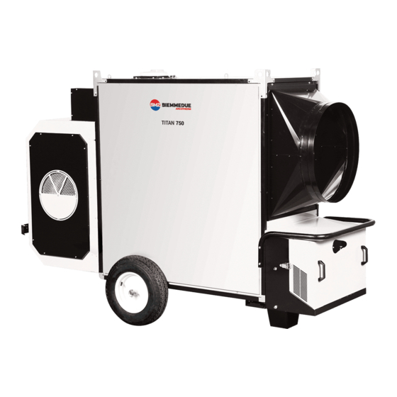
- Page 1 INSTRUCTIONS MANUAL MANUEL D'INSTRUCTIONS SPACE HEATER GENERATEUR D'AIR CHAUD TITAN 750 – TITAN 1000 L-L 261.00-BM 1 / 25...
- Page 2 WARNING BEFORE USING THE HEATER, READ AND UNDERSTAND ALL INSTRUCTIONS AND FOLLOW THEM CAREFULLY. THE MANUFACTURER IS NOT RESPONSIBLE FOR DAMAGES TO GOODS OR PERSONS DUE TO IMPROPER USE OF THE UNITS. GENERAL HAZARD WARNING FAILURE TO COMPLY WITH THE PRECAUTIONS AND INSTRUCTIONS PROVIDED WITH THIS HEATER, CAN RESULT IN DEATH, SERIOUS INJURY AND PROPERTY LOSS OR DAMAGE FROM HAZARDS OF FIRE, EXPLOSION, BURN, ASPHYXIATION, CARBON MONOXIDE POISONING, AND / OR ELECTRICAL SHOCK.
- Page 3 WARNING The heater is designed and approved for use as a construction heater in accordance with Standard ANSI Z83,7 CGA 2.14. CHECK WITH YOUR LOCAL FIRE SAFETY AUTHORITY IF YOU HAVE QUESTIONS ABOUT APPLICATIONS. Other standards govern the use of fuel gases and heat producing products in specific applications.Your local authority can advise you about these.
- Page 4 CONTROL BOARD - SCHÉMA DE FONCTIONNEMENT HOT AIR OUTFLOW SORTIE AIR CHAUD HOISTING BRACKETS ÉTRIERS DE LEVAGE CHIMNEY CHEMINEE SUPPORT/HANDLE SUPPORT/POIGNEE COOLING FAN VENTILATEUR REFROIDISSEMENT WHEEL ROUE COMBUSTION CHAMBER CHAMBRE DE COMBUSTION 10 BURNER BOX BOÎTIER BRÛLEUR BURNER BRULEUR 11 ELECTRICAL PANEL BOX BOÎTIER TABLEAU ÉLECTRIQUE THERMOSTATS L2 BOX BOITIER THERMOSTATS L2...
- Page 5 CONTROL PANEL - TABLEAU DE COMMANDE HEATING-VENTILATION SWITCH TEMPERATURE CONTROLLER INTERRUPTEUR CHAUFFAGE-VENTILATION THERMORÉGULATEUR VOLTAGE LAMP BURNER LIGHT TEMOIN TENSION VOYANT BRÛLEUR OVERHEAT THERMOSTATS CONTROL LAMP, L2 SAFETY THERMOSTAT RESET BUTTON, L2 TEMOIN THERMOSTATS DE SURCHAUFFE, L2 POUSSOIR DE RÉARMEMENT THERMOSTAT DE SÉCURITÉ, L2 ROOM THERMOSTAT PLUG m BURNER RESET BUTTON / LAMP PRISE THERMOSTAT D’AMBIANCE...
- Page 6 MANIFOLD ASSEMBLY – MANIFOLD ASSEMBLY GAS SELECTOR VALVE VALVE SÉLECTEUR GAZ MANIFOLD PRESSURE PORT / PORT PRESSION BRULEUR MANIFOLD PRESSURE REGULATOR / RÉGULATEUR PRESSION MAIN GAS VALVE / SOUPAPE PRINCIPALE GAZ INLET PRESSURE PORT / PORT PRESSION EN ENTRÉE SHUT OFF - FIRING VALVE / VALVE COUPURE L-L 261.00-BM 6 / 25...
-
Page 7: General Advice
IMPORTANT Before using the space heater, carefully read all of the instructions and follow them scrupulously. The manufacturer cannot be held responsible for damage to persons and/or property caused by improper use of the equipment. This instruction manual is an integral part of the equipment and must therefore be stored carefully and passed on with the unit in the event of a change of ownership. -
Page 8: Installation Instructions
Warning This unit may not be used by persons (including children) with reduced physical, sensorial or mental capacities or with limited experience and familiarity unless they are under supervision or instructed on how to use the unit by the person responsible for its safety. 4. - Page 9 Warning Never attempt to switch the heater on or off by connecting the room thermostat (or other control devices) to the electrical power line. The installation and connection of all the other accessories are described in the specific instructions included with each accessory, together with operating instructions.
- Page 10 4.4. MOUNTING THE RIELLO GAS BURNER Warning Riello gas burners are supplied pre-fit with a nozzle for natural gas and a gas selector valve for switching from natural gas to propane or viceversa (see paragraph 4.8). • Remove the box cover and, with an appropriate tool, eliminate metal parts B by following the pre-cut line already traced on the cover.
- Page 11 D - E 1: filter-pressure regulator or filter 2: antivibration joint 3: stopcock 4: gas ramp • Connect the stainless steel flexible hose to the gas valve selector Parts (1), (2) and (3) are available as accessories and are not group, taking care to properly insert the N gas seal: supplied with the heater.
- Page 12 • there must always be a wind deflector to prevent the entrance of ACCORDANCE WITH THE REQUIREMENTS OF THE rain and to prevent smoke from being blocked by the wind; CAN/CGA-B149.1 OR CAN/CGAB149.2 INSTALLATION • flue draft must at least equal the level in the Technical CODES.
- Page 13 4.9. REGULATING COMBUSTION AND ANALYSING COMBUSTION combustion chamber has been heating for a few minutes, the PRODUCTS main fan will start up; Warning The first start-up should always be carried out by a Warning specialised technician checking the correctness of the The fan runs continuously in H+V mode, even when the combustion parameters.
-
Page 14: Maintenance
Display of hours of operation thermostat, while the LED group “- = +” indicates the current Press key (a) twice: the screen shows the operating time in hours temperature compared to the set temperature: [h]: • if the red arrow at the symbol “-“ is ON, it means that the temperature is below the set value and, therefore, the thermostat is ON, i.e., the burner is ON. -
Page 15: Troubleshooting
fire or explosion • Clean with a dry cloth, taking care not to cut or bend the capillary • Make sure that flammable materials are kept a safe distance away tube. • If you smell: • Open the windows immediately 6.7 CLEANING THE INTERIOR OF THE HEATER •... - Page 16 FAULT CAUSE REMEDY • The heater does not start: • Check functioning and position of switch • Check the mains • No power supply • Check power connections • Check fuse lamp is off • Switch (a) in wrong position •...
- Page 17 WIRING DIAGRAM - SCHEMA ELECTRIQUE 240V, 1 , 60Hz FAN MOTOR RELAIS DE RETARD ALLUMAGE MOTEUR VENTILATEUR ANTI-CONDENSATION RESISTANCE FAN THERMOSTAT (setting: 30°C) RÉSISTANCE ANTICONDENSATION THERMOSTAT VENTILATEUR (régulation: 30°C) TM FANS TELE-CONTACTOR FB FUSE TELERUPTEUR VENTILATEUR FUSIBLE RM FANS THERMAL RELAY POWER LAMP RELAIS THERMIQUE VENTILATEUR LAMPE TEMOIN MISE SOUS TENSION...
-
Page 18: Technical Specifications
TECHNICAL SPECIFICATIONS TITAN 750 Burner Model RIELLO R40-N750S Burner Nozzle RIELLO G20 Nominal Heat Input [BTU/h] 750,000 min 7" w.c. Supply pressure [in w.c.] max 10" w.c. Normal Heat input [BTU/h] 740,261 altitude 0 - Manifold pressure [in w.c.] 2.80... - Page 19 TECHNICAL SPECIFICATIONS TITAN 1000 Burner Model RIELLO R40-N900S Burner Nozzle RIELLO G20 Nominal Heat Input [BTU/h] 1,000,000 min 7" w.c. Supply pressure [in w.c.] max 10" w.c. Normal Heat input [BTU/h] 996,801 altitude 0 - Manifold pressure [in w.c.] 2.80 2,000 ft above Burner head position [N°]...
- Page 20 ASSEMBLY INSTRUCTION - NOTICE DE MONTAGE L-L 261.00-BM 20 / 25...
- Page 21 FOOT / HANDLE ASSEMBLY INSTRUCTION - NOTICE DE MONTAGE DU PIED/DE LA POIGNEE Mod. 750 kBTU/h L-L 261.00-BM 21 / 25...
- Page 22 FOOT / HANDLE ASSEMBLY INSTRUCTION - NOTICE DE MONTAGE DU PIED/DE LA POIGNEE Mod. 750 kBTU/h L-L 261.00-BM 22 / 25...
- Page 23 FOOT / HANDLE ASSEMBLY INSTRUCTION - NOTICE DE MONTAGE DU PIED/DE LA POIGNEE Mod 1,000 kBTU/h L-L 261.00-BM 23 / 25...
- Page 24 FOOT / HANDLE ASSEMBLY INSTRUCTION - NOTICE DE MONTAGE DU PIED/DE LA POIGNEE Mod. 1,000 kBTU/h L-L 261.00-BM 24 / 25...
- Page 25 BIEMMEDUE S.p.A. Via Industria,12 - 12062 - Cherasco (CN) - Italy Tel. +39 0172 486111 - Fax +39 0172 488270 www. biemmedue.com - bm2@biemmedue.com L-L 261.00-BM 25 / 25...
Need help?
Do you have a question about the TITAN 750 and is the answer not in the manual?
Questions and answers