
Related Manuals for INSTEON 2450


Summary of Contents for INSTEON 2450
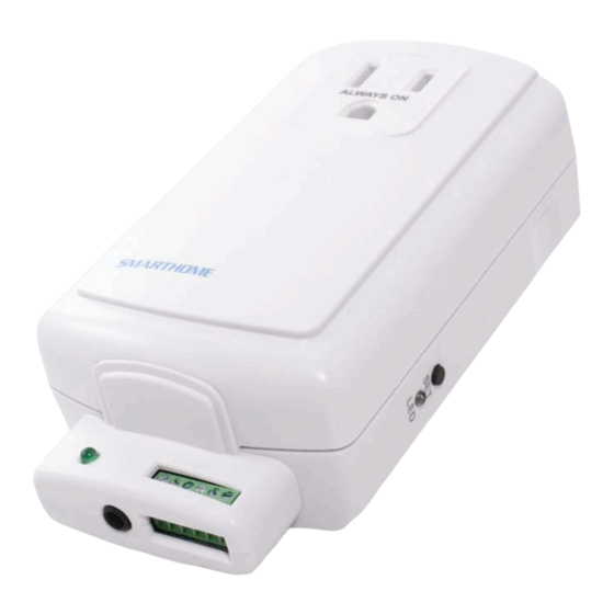
- Page 1 ® INSTEON I/O Linc Low Voltage / Contact Closure Interface Owner’s Manual 2450 Page 1 of 16 Rev: 1/21/2014 7:20 AM...
-
Page 2: Table Of Contents
Setting Up The I/O Linc Output Relay ....................... 7 I/O Linc Output Relay Modes ........................7 Linking An Insteon Controller To Control The I/O Linc Output Relay ............9 Setting The I/O Linc Output Relay Mode ....................10 Setting The I/O Linc Momentary Duration ....................11 Unlinking I/O Linc From An Insteon Controller .................. -
Page 3: About I/O Linc
I/O Linc allows you to monitor and control any low voltage device (such as alarm sensor, electric door strike, etc.) as part of your INSTEON home automation network. With one dry-contact sensor input you can control many INSTEON devices throughout the house. Plus, use the built-in single-pole double-throw (SPDT) switch to connect to any low- voltage-powered device for continuous or momentary operation. -
Page 4: Installation
Don’t plug I/O Linc into a filtered power strip or AC filter • Don’t stack INSTEON home automation devices together by plugging them into each other. Stacked devices may overheat and stop functioning. Also avoid using the pass-through outlets on INSTEON devices for other heat-generating power supplies. •... -
Page 5: Installing I/O Linc
Sensor Terminals Input Linking the I/O Linc Sensor Input to an INSTEON Responder Any device that is Linked to I/O Linc (the load) using these instructions will be controlled when: • The I/O Linc connected to the sensor is either opened or closed •... -
Page 6: Unlinking An Insteon Responder From I/O Linc
NOTE: During linking, you will have the option to turn on remote INSTEON devices when either the connected sensor is closed or when it is opened. Once this is programmed, the opposite action will trigger an OFF command. For example, if you program an ON command to be sent when the I/O Linc connected sensor is closed, opening the sensor will trigger an OFF command. -
Page 7: Triggering The I/O Linc Output Relay From Its Sensor Input
OFF command when the sensor is opened, or vice versa, the output relay will: • Close when an INSTEON ON command is sent (as a result of a sensor) • Open when an INSTEON OFF command is sent (as a result of a sensor) - Page 8 In this example, a KeypadLinc is programmed to control sprinklers. When KeypadLinc sends an ON command, I/O Linc will close the relay, turning on the sprinklers. They will remain on until KeypadLinc sends an OFF command, opening the I/O Linc relay and turning off the sprinklers. NOTE ABOUT MOMENTARY MODES: The relay will remain open until triggered.
-
Page 9: Linking An Insteon Controller To Control The I/O Linc Output Relay
Once you have chosen the desired output relay mode, proceed to linking and follow the instructions for the mode you have chosen. See Linking an INSTEON Controller to Control the I/O Linc Output Relay. Linking an INSTEON Controller to Control the I/O Linc Output Relay NOTE: The following steps assume the I/O Linc output relay is still set to the factory default Latching (Continuous) Mode. -
Page 10: Setting The I/O Linc Output Relay Mode
Once you have selected the desired output relay mode, find it below and follow the instructions to Link I/O Linc to an INSTEON Controller. Latching (Continuous) 1) Tap the Set button on I/O Linc to set the relay to the desired state. For example, if you want an ON command to open the relay, set the relay to be open. -
Page 11: Setting The I/O Linc Momentary Duration
NOTE: The momentary duration can be set manually anywhere from 2 seconds up to 25 seconds. Or you can use INSTEON home automation software (such as HouseLinc) to set the momentary duration anywhere from 0.2 seconds up to 25 seconds. -
Page 12: Creating An Insteon Scene
Controller. INSTEON scenes are very easy to set up – just Link more than one responder to the same On/Off or Scene button on a Controller. Then, when you press any of the Linked buttons on the Controller, all of the INSTEON devices Linked in the scene will respond as a group. -
Page 13: Removing An I/O Linc X10 Address From Its Sensor Input
3) Using an X10 controller, send either ON (for I/O Linc to send an X10 ON command when the sensor closes and an X10 OFF command when the sensor opens) or OFF (for I/O Linc to send an X10 ON command when the sensor opens and an X10 OFF command when the sensor closes) I/O Linc will beep and its Status LED will stop blinking and turn on solid Removing an I/O Linc X10 Address from its Sensor Input... -
Page 14: Specifications, Certification, And Warranty
Problem Possible Cause Solution The controller or Make sure two dual-band INSTEON devices are responder and I/O Linc properly installed to bridge the two power line may be on opposite power phases. line phases. Add additional INSTEON devices or move around The INSTEON signal may existing INSTEON devices. -
Page 15: Certification
Set Button: Toggles output relay On/Off. Also used for setup. Momentary Duration: Adjustable, 2 - 105 minutes Operation Modes: INSTEON only, X10 only, INSTEON and X10 Combo Mode Combo mode Message Order: INSTEON, INSTEON confirmation, X10 Multi-Way Circuit Support: Setup Memory:... - Page 16 The repair, replacement, or refund that is provided for above shall be the full extent of Seller’s liability with respect to this product. For repair or replacement during the warranty period, call the INSTEON Support Line at 866-243-8022 with the Model # and...
Need help?
Do you have a question about the 2450 and is the answer not in the manual?
Questions and answers