Table of Contents
Advertisement
Quick Links
Advertisement
Table of Contents

Related Manuals for Asus H310I-IM-A R2.0


Summary of Contents for Asus H310I-IM-A R2.0
- Page 1 H310I-IM-A R2.0...
- Page 2 Product warranty or service will not be extended if: (1) the product is repaired, modified or altered, unless such repair, modification of alteration is authorized in writing by ASUS; or (2) the serial number of the product is defaced or missing.
-
Page 3: Table Of Contents
Contents Chapter 1: Product overview Package contents ................. 1-1 Features ..................1-1 1.3 Specifications ................1-2 Chapter 2: Motherboard information Before you proceed ..............2-1 Motherboard layout ..............2-2 Central Processing Unit (CPU) ........... 2-4 2.3.1 Installing the CPU ............2-5 2.3.2 CPU heatsink and fan assembly installation .... - Page 4 CPU Core Voltage, 3.3V Voltage, 5V Voltage, 12V Voltage ..3-14 Q-Fan Configuration ..............3-14 CPU Q-Fan Control [PWM Mode] ..........3-14 Chassis Fan(s) Configuration ............3-15 Boot menu .................. 3-18 Boot Configuration ............... 3-18 Tool menu ................... 3-22 Exit menu ..................3-23 Appendix Notices .......................A-1 ASUS contact information ...............A-5...
-
Page 5: Chapter 1: Product Overview
Chapter 1 Product overview Package contents Check your industrial motherboard package for the following items. 1 x ASUS H310I-IM-A R2.0 Motherboard 2 x Serial ATA 6.0 Gb/s cables 2 x M.2 screw packages 1 x ASUS I/O Shield NOTE: If any of the above items is damaged or missing, contact your distributor or sales representative immediately. -
Page 6: Specifications
Turbo Boost Technology 2.0* ® * CPU only supports up to 65W. ** Intel Turbo Boost Technology 2.0 support depends on the CPU ® types. *** Refer to www.asus.com for Intel CPU support list. ® Chipset Intel H310 Chipset ®... - Page 7 1 x Flat panel display brightness connector 1 x AT/ATX mode selection header GPIO 1 x 8-bit GPIO header 128 Mb Flash ROM, UEFI AMI BIOS, PnP, DMI 3.0, WfM 2.0, SM BIOS 3.1, ACPI 6.1, Multi-language BIOS, ASUS EZ Flash 3, BIOS features Last Modified Log, ErP Ready, ASUS Self-Recovering BIOS, ASUS Commercial Kit Manageability WfM 2.0, DMI 2.0, WOL by PME...
- Page 8 Operation 0~60°C Temperature Non-Operation -40~85°C Temperature Relative Humidity 0%~85% OS support Windows 10 (64-bit) ® Form Factor Mini-ITX Form Factor, 6.7”x 6.7” (17.0cm x 17.0cm) NOTE: Specifications are subject to change without notice. H310I-IM-A R2.0...
-
Page 9: Chapter 2: Motherboard Information
Chapter 2 Motherboard information Before you proceed Take note of the following precautions before you install motherboard components or change any motherboard settings. CAUTION! • Unplug the power cord from the wall socket before touching any component. • Before handling components, use a grounded wrist strap or touch a safely grounded object or a metal object, such as the power supply case, to avoid damaging them due to static electricity. • Hold components by the edges to avoid touching the ICs on them. • Whenever you uninstall any component, place it on a grounded antistatic pad or in the bag that came with the component. -
Page 10: Motherboard Layout
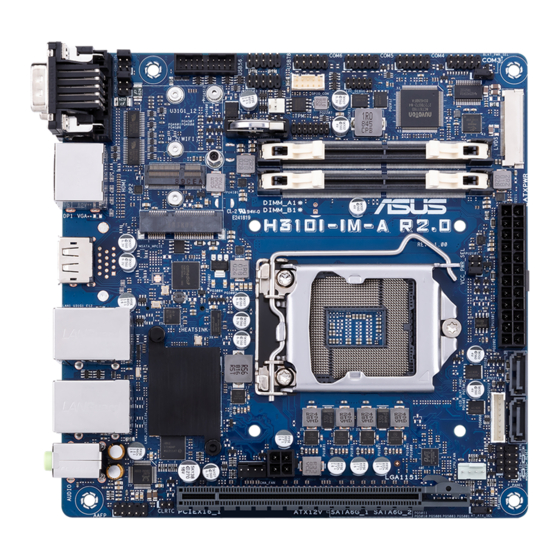
DDR4 SO-DIMM_B1* (64bit, 260-pin module) 2242 MSATA_MPCIE 128Mb BIOS Place this side towards the rear 1074 of the chassis M.2_(SOCKET3) Intel ® I219V LGA1151 LAN1_U31G1_E12 Intel ® H310 LAN2_U31G1_E34 Intel ® ATX12V I211AT DIGI CHA_FAN CPU_FAN +VRM AUDIO PCIEX16_1 CLRTC AT_ATX_SEL H310I-IM-A R2.0... - Page 11 Page Connectors/Jumpers/Slots COM1 Ring/+5V/+12V selection jumpers (6-pin COM1_ESL, COM2_ESL) 2-11 LCD panel monitor switch header (2-pin PANEL_SW) 2-14 USB 3.1 Gen 1 connector (20-1 pin U31G1_12) 2-14 USB 2.0 connectors (10-pin USB56, USB78) 2-15 General purpose input/output connector (GPIO_CON) 2-15 Serial port connectors (10-pin COM3, COM4, COM5, COM6) 2-21 TPM connector (14-1 pin TPM) 2-16 Display panel backlight power selection (3-pin BLKT_PWR_SEL) 2-10 LVDS connector (40-pin LVDS) 2-18 10. DDR4 SO-DIMM slots 11. Display panel VCC power selection (6-pin VCC_PWR_SEL) 2-11 12. ATX power connectors (24-pin EATXPWR, 4-pin ATX12V) 2-21 13. Flat panel display brightness connector (8-pin LCD_BLKT_PANEL) 2-22 14. Serial ATA 6.0Gb/s connectors (7-pin SATA6G_1/2) 2-17 15. System panel connector (10-1 pin F_PANEL) 2-17 16. Speaker connector (4-pin SPEAKER) 2-18 17.
-
Page 12: Central Processing Unit (Cpu)
Central Processing Unit (CPU) The motherboard comes with a surface mount LGA1151 socket designed for the Intel 8th Generation Core™ i7 / Core™ i5 / Core™ i3, Pentium , and Celeron ® ® ® processors. H310I-IM-A R2.0 CPU socket LGA1151 IMPORTANT: Unplug all power cables before installing the CPU. CAUTION! • Upon purchase of the motherboard, ensure that the PnP cap is on the socket and the socket contacts are not bent. Contact your retailer immediately if the PnP cap is missing, or if you see any damage to the PnP cap/socket contacts/motherboard components. The manufacturer will shoulder the cost of repair only if the damage is shipment/transit-related. • Keep the cap after installing the motherboard. The manufacturer will process Return Merchandise Authorization (RMA) requests only if the motherboard comes with the cap on the LGA1151 socket. • The product warranty does not cover damage to the socket contacts resulting from incorrect CPU installation/removal, or misplacement/loss/ incorrect removal of the PnP cap. H310I-IM-A R2.0... -
Page 13: Installing The Cpu
2.3.1 Installing the CPU CAUTION! LGA1156 CPU is not compatible with the LGA1151 socket. DO NOT install an LGA1156 CPU on the LGA1151 socket. Chapter 2: Motherboard information... - Page 14 H310I-IM-A R2.0...
-
Page 15: Cpu Heatsink And Fan Assembly Installation
2.3.2 CPU heatsink and fan assembly installation CAUTION! Apply the Thermal Interface Material to the CPU heatsink and CPU before you install the heatsink and fan if necessary. To install the CPU heatsink and fan assembly Chapter 2: Motherboard information... - Page 16 To uninstall the CPU heatsink and fan assembly H310I-IM-A R2.0...
-
Page 17: System Memory
System memory This motherboard comes with two Double Data Rate 4 (DDR4) Small Outline Dual Inline Memory Module (SO-DIMM) sockets. The figure below illustrates the location of the DDR4 SO-DIMM sockets: SO-DIMM_A1* SO-DIMM_B1* Channel Sockets Channel A SO-DIMM_A1 Channel B SO-DIMM_B1 H310I-IM-A R2.0 204-pin DDR4 SO-DIMM sockets Recommended memory configuration DIMM_A1* DIMM_B1* DIMM_A1* DIMM_B1* Installing a DIMM To remove a DIMM Chapter 2: Motherboard information... -
Page 18: Jumpers
Jumpers Clear RTC RAM (2-pin CLRTC) This header allows you to clear the CMOS RTC RAM data of the system setup information such as date, time, and system passwords. CLRTC PIN 1 H310I-IM-A R2.0 Clear RTC RAM To erase the RTC RAM: 1. Turn OFF the computer and unplug the power cord. 2. Use a metal object such as a screwdriver to short the two pins. 3. Plug the power cord and turn ON the computer. 4. Hold down the <Del> key during the boot process and enter BIOS setup to re-enter data. NOTE: If the steps above do not help, remove the onboard battery and move the jumper again to clear the CMOS RTC RAM data. After clearing the CMOS, reinstall the battery. Display panel backlight power selection (3-pin BLKT_PWR_SEL) - Page 19 COM1/2 Ring/+5V/+12V selection (6-pin COM1_SEL, COM2_SEL) COM1_SEL +12V (Default) COM2_SEL +12V (Default) H310I-IM-A R2.0 COM1/COM2 Ring/+5V/+12V selection Setting Pins +12V Ring (Default) Display panel VCC power selection (6-pin VCC_PWR_SEL) VCC_PWR_SEL (Default) H310I-IM-A R2.0 Display panel VCC power Setting Pins 3V (Default) Chapter 2: Motherboard information 2-11...
-
Page 20: Connectors
AT/ATX mode selection (3-pin AT_ATX_SEL) AT_ATX_SEL ATX mode AT mode (Default) H310I-IM-A R2.0 AT/ATX mode selection Pins 1-2 (Default) ATX mode AT mode Connectors 2.6.1 Rear panel connectors Serial port connectors (COM). These ports connect a modem, or other devices that conform with serial specification. DisplayPorts. These ports are for DisplayPort-compatible devices. LAN (RJ-45) ports. These ports allow Gigabit connection to a Local Area Network (LAN) through a network hub. LAN port LED indications Speed... - Page 21 Line Out port (lime). This port connects to a headphone or a speaker. In the 4.1, 5.1and 7.1-channel configurations, the function of this port becomes Front Speaker Out. Microphone port (pink). This port connects to a microphone. Refer to the audio configuration table for the function of the audio ports in 2.1, 4.1, 5.1, or 7.1-channel configuration. Audio 2.1, 4.1, 5.1 or 7.1-channel configuration Headset Port 4.1-channel 5.1-channel 7.1-channel 2.1-channel Line Ourt (Rear Front Speaker Front Speaker Front Speaker Out Front Speaker Out panel) Rear Speaker MIC(Rear panel) Rear Speaker Out Rear Speaker Out Out Headphone (Front Center/Subwoofer...
-
Page 22: Internal Connectors
2.6.2 Internal connectors LCD panel monitor switch header (2-pin PANEL_SW) This 2-pin header is for connecting a monitor switch that can turn off the LCD panel display backlight. PANEL_SW MON_SW# PIN 1 H310I-IM-A R2.0 Display panel power button USB 3.1 Gen 1 connector (20-1 pin U31G1_12) Connect a USB 3.1 Gen 1 module to this connector for additional USB 3.1 Gen 1 front or rear panel ports. This connector complies with USB 3.1 Gen 1 specifications and provides faster data transfer speeds of up to 5 Gbps, faster charging time for USB-chargeable devices, optimized power efficiency, and backward compatibility with USB 2.0. U31G1_12 PIN 1 H310I-IM-A R2.0 USB 3.1 Gen1 connector... - Page 23 USB 2.0 connectors (10-pin USB56, USB78) These connectors are for USB 2.0 ports. Connect the USB cable to these connectors. These USB connectors comply with USB 2.0 specification that supports up to 480 Mbps connection speed. USB78 USB56 PIN 1 PIN 1 H310I-IM-A R2.0 USB2.0 connectors CAUTION! Never connect a 1394 cable to the USB connector. Doing so will damage the motherboard. NOTE: The USB cable is purchased separately. General purpose input/output connector (GPIO_CON) This connector is for a general purpose input/output module which allows you to customize the digital signal input/output. GPIO_CON PIN 1 H310I-IM-A R2.0 GPIO connector Chapter 2: Motherboard information...
- Page 24 CPU and chassis fan connectors (4-pin CPU_FAN, 4-pin CHA_FAN) Connect the fan cables to the fan connectors on the motherboard, ensuring that the black wire of each cable matches the ground pin of the connector. CHA_FAN CPU_FAN H310I-IM-A R2.0 Fan connectors CAUTION: Do not forget to connect the fan cables to the fan connectors. Insufficient air flow inside the system may damage the motherboard components. These are not jumpers! Do not place jumper caps on the fan connectors!
- Page 25 Front panel system panel connector (10-1 pin F_PANEL) This connector supports several chassis-mounted functions. F_PANEL (NC) RSTCON#_PANEL PWRBTN# PWR_LED- HDD_LED- PWR_LED+ HDD_LED+ PIN 1 H310I-IM-A R2.0 System panel connector • System power LED (2-pin +PWR_LED) This 2-pin connector is for the system power LED. Connect the chassis power LED cable to this connector. The system power LED lights up when you turn on the system power, and blinks when the system is in sleep mode. • Hard disk drive activity LED (2-pin +HDD_LED) This 2-pin connector is for the HDD Activity LED. Connect the HDD Activity LED cable to this connector. The IDE LED lights up or flashes when data is read from or written to the HDD.
- Page 26 LVDS0_D1+ LVDS0_D2- LVDS0_D2+ LVDS0_D3- LVDS0_D3+ PIN 1 H310I-IM-A R2.0 LVDS connector 10. Speaker connector (4-pin SPEAKER) The 4-pin connector is for the chassis-mounted system warning speaker. The speaker allows you to hear system beeps and warnings. SPEAKER SPKO PIN 1 H310I-IM-A R2.0 SPEAKER connector...
- Page 27 11. M.2 socket 3 This socket allows you to install an M.2 SSD module. Bottom: M.2(SOCKET3) 2280 2260 2242 H310I-IM-A R2.0 M.2(SOCKET3) NOTES: • The M.2 SSD module is purchased separately. • This socket supports M Key and 2242/2260/2280 storage devices. 12. M.2 Wi-Fi This socket connects to an M.2 Wi-Fi device. M.2(WIFI) 2230 H310I-IM-A R2.0 M.2(Wi-Fi) NOTE: The M.2 Wi-Fi module is purchased separately. Chapter 2: Motherboard information 2-19...
- Page 28 13. mSATA/mPCIe combo slot (MSATA_MPCIE) This slot allows you to install a full length mSATA or mini-PCIe card, providing you with expandability and connectivity solutions for an optimal system performance. MSATA_MPCIE H310I-IM-A R2.0 mSATA/mPCIe combo slot 14. LPC Debug header This header allows connection to a LPC debug card. LPC Debug header H310I-IM-A R2.0 LPC Debug header IMPORTANT! • Scan the QR code to view the meaning of each debug code. • Debug codes are only available for ASUS LPC debug card. • Contact your region sales representative for LPC debug header ordering. H310I-IM-A R2.0 2-20...
- Page 29 15. Serial port connectors (10-pin COM3, COM4, COM5, COM6) These connectors are for serial (COM) ports. Connect the serial port cables to these connectors, then install the module to a slot opening at the back of the system chassis. COM6、COM5、COM4、COM3 PIN 1 H310I-IM-A R2.0 Serial port (COM) connectors NOTE: The serial port cables are purchased separately. 16. ATX power connectors (24-pin EATXPWR, 4-pin ATX12V) Correctly orient the ATX power supply plugs into these connectors and push down firmly until the connectors completely fit. ATX12V...
- Page 30 AAFP PIN 1 PIN 1 HD-audio-compliant Legacy AC’97 pin definition compliant definition H310I-IM-A R2.0 Front panel audio connector IMPORTANT! • We recommend that you connect a high-definition front panel audio module to this connector to avail of the motherboard’s high-definition audio capability. • If you want to connect a high-definition front panel audio module to this connector, set the HD Audio Controller item in the BIOS setup to [Enabled]. 18. Flat panel display brightness connector (8-pin LCD_BLKT_PANEL) This connector is for the LCD panel brightness controls.
-
Page 31: Chapter 3: Bios Setup
Always shut down the system properly from the operating system. IMPORTANT: • Visit the ASUS website at www.asus.com to download the latest BIOS file for this motherboard. • The default BIOS settings for this motherboard apply to most working conditions and ensures optimal performance. -
Page 32: Bios Menu Screen
Clock (RTC) RAM to clear the BIOS password. See section 2.5 Jumpers for information on how to erase the RTC RAM. The Administrator or User Password items on top of the screen show • the default Not Installed. After you set a password, these items show Installed. H310I-IM-A R2.0... - Page 33 Administrator Password If you have set an administrator password, we recommend that you enter the administrator password for accessing the system. To set an administrator password: Select the Administrator Password item and press <Enter>. From the Create New Password box, key in a password, then press <Enter>.
-
Page 34: Advanced Menu
This item allows you to select the ASPM state for energy-saving conditions. Configuration options: [Disabled] [L0s] [L1] [L0sL1] [Auto] L1 Substates [Disabled] This item allows you to select the PCI Express L1 Substates settings. Configuration options: [Disabled] [L1.1] [L1.2] [L1.1 & L1.2] H310I-IM-A R2.0... -
Page 35: Cpu Configuration
CPU and PCH sides must be enabled for the ASPM to take effect. Configuration options: [Disabled] [L1] PEG-ASPM [Disabled] This item allows you to select the ASPM state for energy-saving conditions, or use the ASUS optimized energy saving profile. Configuration options: [Disabled] [Auto] [ASPM L0s] [ASPM L1] [ASPM L0sL1] 3.3.2 CPU Configuration The items in this menu show CPU-related information the BIOS automatically detects. - Page 36 Allows you to disable or enable the CPU C7 report to OS. Configuration options: [Disabled] [CPU C7] [CPU C7s] CPU C8 Report [Enabled] Allows you to disable or enable the CPU C8 report to OS. Configuration options: [Enabled] [Disabled] H310I-IM-A R2.0...
-
Page 37: System Agent (Sa) Configuration
Package C State Limit [Auto] Allows you to disable or enable the whole C-State package support. Configuration options: [C0/C1] [C2] [C3] [C6] [C7] [C7s] [C8] [Auto] [CPU Default] CFG Lock [Disabled] This item allows you to enable or disable the CFG lock. Configuration options: [Disabled] [Enabled] Intel(R) Speed Shift Technology [Enabled] This item allows you to enable or disable Intel(R) Speed Shift Technology... -
Page 38: Pch Configuration
When disabled, the hot plug function of SATA ports are disabled. Configuration options: [Disabled] [Enabled] Smart Self Test [Enabled] This item allows you to enable or disable the SMART Self Test on all HDDs during POST. Configuration options: [Disabled] [Enabled] H310I-IM-A R2.0... -
Page 39: Lvds Configuration
SATA6G_1~2(Gray) [Enabled] Allow you to enable/disable the SATA6G_1~2 port. Configuration options: [Disabled] [Enabled] SATA6G_1~2 Hot Plug [Disabled] These items allow you to enable/disable SATA Hot Plug Support. Configuration options: [Disabled] [Enabled] M.2(SOCKET3) [Enabled] Allow you to enable/disable the M.2(SOCKET3). Configuration options: [Disabled] [Enabled] 3.3.6 PCH-FW Configuration... -
Page 40: Onboard Devices Configuration
M.2 Configuration [Auto] [Auto] Auto-detects the M.2 device mode. [SATA Mode] Only supports M.2 SATA devices. [PCIE Mode] Only supports M.2 PCIE devices. Intel LAN2 Controller [Enabled] [Enabled] Enables the Intel LAN controller 2. [Disabled] Disables the controller. H310I-IM-A R2.0 3-10... - Page 41 Intel LAN2 PXE OPROM [Disabled] This item appears only when you set the previous item to [Enabled] and allows you to enable or disable the PXE Option ROM of the Intel LAN controller 2. Configuration options: [Disabled] [Enabled] Wi-Fi Controller [Enabled] [Enabled] Enables the Wi-Fi controller.
-
Page 42: Apm Configuration
Enable this item to allow your system to comply with CEC (California Energy Commission) regulations to save some power at S0 state. Configuration options: [Enable] [Disabled] 3.3.10 USB Configuration The USB Devices item lists auto-detected values. If no USB device is detected, the item shows None. H310I-IM-A R2.0 3-12... -
Page 43: Network Stack Configuration
Legacy USB Support [Enabled] [Enabled] Enables the support for USB devices on legacy operating systems (OS). [Disabled] USB devices are only available when running BIOS Setup. [Auto] Allows the system to detect the presence of USB devices at startup. If detected, the USB controller legacy mode is enabled. -
Page 44: Cpu / Motherboard Temperature [Xxxºc/Xxxºf]
Sets to [Silent] to minimize the fan speed for quiet CPU fan operation. [Turbo] Sets to [Turbo] to achieve maximum CPU fan speed. [Manual] Sets to [Manual] to assign detailed fan speed control parameters. The following four items appear only when you set CPU Fan Profile to [Manual]. H310I-IM-A R2.0 3-14... -
Page 45: Chassis Fan(S) Configuration
CPU Upper Temperature [70] Use the <+> and <-> keys to adjust the upper limit of the CPU temperature. The values range from 25ºC to 75ºC. CPU Fan Max. Duty Cycle(%) [100] Use the <+> and <-> keys to adjust the maximum CPU fan duty cycle. The values range from 20% to 100%. - Page 46 This function allows the fan to run at 0% duty cycle when the temperature of the source is dropped below the lower temperature. Configuration options: [Disabled] [Enabled] Chassis Fan Lower Temperature [40] Displays the lower limit of the chassis temperature. H310I-IM-A R2.0 3-16...
- Page 47 Fan Control Mode [SMART FAN IV Mode] Select fan control mode. Configuration options: [Manual Mode] [Thermal Cruise Mode] [SMART FAN IV Mode] The following 6 items appear only when you set Fan Control Mode to [Smart FAN IV Mode]. Temperature source [SYSTIN] Temperature 1~4 [xx] Input temperature setting.
-
Page 48: Boot Menu
Post Report [5 sec] This item appears only when you set Boot Logo Display to [Disabled]. This item allows you to select a desired post report waiting time. Configuration options: [1 sec] ~ [10 sec] [Until Press ESC]. H310I-IM-A R2.0 3-18... - Page 49 Bootup NumLock State [Enabled] This item allows you to enable or disable power-on state of the NumLock. Configuration options: [Disabled] [Enabled] Wait for ‘F1’ If Error [Enabled] When this item is set to [Enabled], the system waits for the F1 key to be pressed when error occurs.
- Page 50 This item allows you to save the downloaded PK to a USB storage device. Set New Key This item allows you to load the downloaded PK from a USB storage device. The PK file must be formatted as a UEFI variable structure with time-based authenticated variable. H310I-IM-A R2.0 3-20...
- Page 51 Delete Key This item allows you to delete the PK from your system. Once the PK is deleted, all the system’s Secure Boot keys will not be active. KEK Management The KEK (Key-exchange Key or Key Enrollment Key) manages the Signature database (db) and Revoked Signature database (dbx).
-
Page 52: Tool Menu
These items specify the boot device priority sequence from the available devices. The number of device items that appears on the screen depends on the number of devices installed in the system. To select the boot device during system startup, press <F8> when ASUS Logo appears. Boot Override These items displays the available devices. -
Page 53: Exit Menu
Exit menu The Exit menu items allow you to load the optimal default values for the BIOS items, and save or discard your changes to the BIOS items. You can access the EZ Mode from the Exit menu. Load Optimized Defaults This option allows you to load the default values for each of the parameters on the Setup menus. - Page 54 H310I-IM-A R2.0 3-24...
-
Page 55: Appendix
Appendix Notices FCC Compliance Information Responsible Party: Asus Computer International Address: 48720 Kato Rd., Fremont, CA 94538, USA Phone / Fax No: (510)739-3777 / (510)608-4555 This device complies with part 15 of the FCC Rules. Operation is subject to the following two conditions: (1) This device may not cause harmful interference, and (2) this device must accept any interference received, including interference that may cause undesired operation. - Page 56 : (1) l’appareil ne doit pas produire de brouillage, et (2) l’utilisateur de l’appareil doit accepter tout brouillage radioélectrique subi, même si le brouillage est susceptible d’en compromettre le fonctionnement. CAN ICES-3(B)/NMB-3(B) VCCI: Japan Compliance Statement Class B ITE KC: Korea Warning Statement H310I-IM-A R2.0...
- Page 57 ASUS Recycling/Takeback Services ASUS recycling and takeback programs come from our commitment to the highest standards for protecting our environment. We believe in providing solutions for you to be able to responsibly recycle our products, batteries, other components as well as the packaging materials.
- Page 58 доступний на: www.asus.com/support Cijeli tekst EU izjave o sukladnosti dostupan je na: www.asus.com/support Türkçe AsusTek Computer Inc., bu aygıtın temel gereksinimlerle ve ilişkili Čeština Společnost ASUSTeK Computer Inc. tímto prohlašuje, že toto Yönergelerin diğer ilgili koşullarıyla uyumlu olduğunu beyan eder.
-
Page 59: Asus Contact Information
+1-510-739-3777 +1-510-608-4555 Web site http://www.asus.com/us/ Technical Support Support fax +1-812-284-0883 Telephone +1-812-282-2787 Online support http://qr.asus.com/techserv ASUS COMPUTER GmbH (Germany and Austria) Address Harkort Str. 21-23, 40880 Ratingen, Germany +49-2102-959931 Web site http://www.asus.com/de Online contact http://eu-rma.asus.com/sales Technical Support Telephone +49-2102-5789555 Support Fax...
Need help?
Do you have a question about the H310I-IM-A R2.0 and is the answer not in the manual?
Questions and answers