Table of Contents
Advertisement
Advertisement
Table of Contents

Related Manuals for Asus PRIME H310M-E


Summary of Contents for Asus PRIME H310M-E
- Page 1 PRIME H310M-E...
- Page 2 Product warranty or service will not be extended if: (1) the product is repaired, modified or altered, unless such repair, modification of alteration is authorized in writing by ASUS; or (2) the serial number of the product is defaced or missing.
-
Page 3: Table Of Contents
Contents Safety information ..................iv About this guide ..................iv Package contents ..................vi PRIME H310M-E specifications summary ..........vi Chapter 1 : Product introduction Motherboard overview ................1-1 Central Processing Unit (CPU) ..............1-7 System memory ..................1-8 M.2 Anchor Installation ................1-9... -
Page 4: Safety Information
Safety information Electrical safety • To prevent electrical shock hazard, disconnect the power cable from the electrical outlet before relocating the system. • When adding or removing devices to or from the system, ensure that the power cables for the devices are unplugged before the signal cables are connected. If possible, disconnect all power cables from the existing system before you add a device. -
Page 5: Conventions Used In This Guide
Refer to the following sources for additional information and for product and software updates. ASUS websites The ASUS website provides updated information on ASUS hardware and software products. Refer to the ASUS contact information. Optional documentation Your product package may include optional documentation, such as warranty flyers, that may have been added by your dealer. -
Page 6: Package Contents
6-core or higher processors; DDR4 2400MHz and higher memory modules will run at max. 2400MHz on Intel® 8th Generation 4-core processors. *** Refer to www.asus.com for the Memory QVL (Qualified Vendors List) 1 x PCI Express 3.0/2.0 x16 slot (at x16 mode) - Page 7 ASUS 5X PROTECTION III - ASUS SafeSlot Core - Fortified PCIe Slot prevents damage - ASUS LANGuard - Protects against LAN surges, lightning strikes and static - electricity discharges - ASUS Overvoltage Protection - World-class circuit-protecting power design - ASUS Stainless Steel Back I/O - 3x corrosion-resistance for greater durability...
- Page 8 1 x Clear CMOS jumper (2-pin) 128 Mb Flash ROM, UEFI AMI BIOS, PnP, SM BIOS 3.1, ACPI 6.1, Multi- language BIOS, ASUS EZ Flash 3, CrashFree BIOS 3, F6 Qfan Control, F3 My BIOS features Favorites, Last Modified log, F12 PrintScreen, and ASUS DRAM SPD (Serial...
-
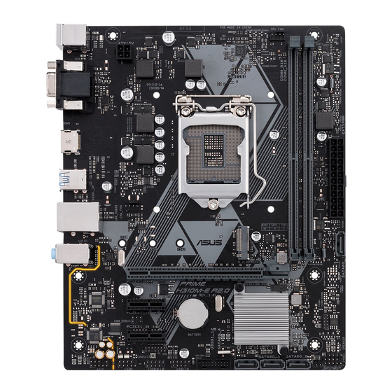
Page 9: Motherboard Overview
CHA_FAN LAN_USB56 M.2(SOCKET3) PCIE SATA IRST SATA6G_1 2280 2260 2242 AUDIO Realtek 8111H PCIEX16 PRIME H310M-E Super PCIEX1_1 Intel ® 128Mb H310 BIOS PCIEX1_2 U31G1_12 USB914 USB1011 SATA6G_4 SATA6G_3 SATA6G_2 SPEAKER AAFP CLRTC F_PANEL 13 12 Scan the QR code to get the detailed pin definitions. ASUS PRIME H310M-E... - Page 10 For a fully configured system, we recommend that you use a power supply unit (PSU) that complies with ATX 12 V Specification 2.0 (or later version) and provides a minimum power of 350 W. Ensure this PSU type has 24-pin and 4-pin power plugs. • We recommend that you use a PSU with higher power output when configuring a system with more power-consuming devices or when you intend to install additional devices. The system may become unstable or may not boot up if the power is inadequate. • DO NOT forget to connect the 4-pin ATX +12V power plug. Otherwise,the system will not boot up. • If you are uncertain about the minimum power supply requirement for your system, refer to the Recommended Power Supply Wattage Calculator at http://support. asus.com/PowerSupplyCalculator/PSCalculator.aspx?SLanguage=en-us for details. CPU and chassis fan connectors (4-pin CPU_FAN, 4-pin CHA_FAN) Connect the fan cables to the fan connectors on the motherboard, ensuring that the black wire of each cable matches the ground pin of the connector. Do not forget to connect the fan cables to the fan connectors. Insufficient air flow inside the system may damage the motherboard components. These are not jumpers! Do not place jumper caps on the fan connectors! The CPU_FAN connector supports a CPU fan of maximum 0.5A (6 W) fan power. Intel LGA1151 CPU socket ® Install Intel LGA1151 CPU into this surface mount LGA1151 socket, which is ®...
- Page 11 Speaker connector (4-pin SPEAKER) The 4-pin connector is for the chassis-mounted system warning speaker. The speaker allows you to hear system beeps and warnings. System panel connector (10-1 pin F_PANEL) This connector supports several chassis-mounted functions. Clear RTC RAM (2-pin CLRTC) CLRTC This header allows you to clear the CMOS RTC RAM data of the system setup information such as date, time, and system passwords. To erase the RTC RAM: PIN 1 Turn OFF the computer and unplug the power cord. Use a metal object such as a screwdriver to short the two pins. Plug the power cord and turn ON the computer. Hold down the <Del> key during the boot process and enter BIOS setup to re-enter data. If the steps above do not help, remove the onboard battery and short the two pins again to clear the CMOS RTC RAM data. After clearing the CMOS, reinstall the battery. ASUS PRIME H310M-E...
- Page 12 USB 3.1 Gen 1 (up to 5Gb/s) connector (20-1 pin U31G1_12) Connect a USB 3.1 Gen 1 module to this connector for additional USB 3.1 Gen 1 front or rear panel ports. This connector complies with USB 3.1 Gen 1 specifications and provides faster data transfer speeds of up to 5 Gbps, faster charging time for USB-chargeable devices, optimized power efficiency, and backward compatibility with USB 2.0. USB 2.0 connectors (10-1 pin USB78, USB914) Connect a USB module cable to any of these connectors, then install the module to a slot opening at the back of the system chassis. These USB connectors comply with USB 2.0 specifications and supports up to 480Mbps connection speed. Digital audio connector (4-1 pin SPDIF_OUT) Connect the S/PDIF Out module cable to this connector, then install the module to a slot opening at the back of the system chassis. PIN 1 SPDIF_OUT Serial port connector (10-1 pin COM) Connect the serial port module cable to this connector, then install the module to a slot opening at the back of the system chassis.
-
Page 13: Rear Panel Connectors
LAN (RJ-45) port. This port allows Gigabit connection to a Local Area Network (LAN) through a network hub. LAN port LED indications Speed Activity Link Activity/Link LED Speed LED Status Description Status Description No link 10Mbps connection Orange Linked ORANGE 100Mbps connection Orange Data activity GREEN 1Gbps connection (Blinking) LAN port Orange Ready to wake (Blinking then up from S5 mode steady) ASUS PRIME H310M-E... - Page 14 Line In port (light blue). This port connects to the tape, CD, DVD player, or other audio sources. Line Out port (lime). This port connects to a headphone or a speaker. In the 4.1, 5.1and 7.1-channel configurations, the function of this port becomes Front Speaker Out. Microphone port (pink). This port connects to a microphone. Refer to the audio configuration table for the function of the audio ports in 2.1, 4.1, 5.1, or 7.1-channel configuration. Audio 2.1, 4.1, 5.1 or 7.1-channel configuration Headset Port 4.1-channel 5.1-channel 7.1-channel 2.1-channel Light Blue (Rear Rear Speaker Rear Speaker Line In Rear Speaker Out panel) Front Speaker Front Speaker Lime (Rear panel) Line Out Front Speaker Out Pink (Rear panel) Mic In...
-
Page 15: Central Processing Unit (Cpu)
Central Processing Unit (CPU) This motherboard comes with a surface mount LGA1151 socket designed for the 8th Generation Intel Core™ i7 / Core™ i5 / Core™ i3, ® Pentium , and Celeron processors. ® ® Unplug all power cables before installing the CPU. • Ensure that you install the correct CPU designed for the LGA1151 socket only. DO NOT install a CPU designed for LGA1150, LGA1155 and LGA1156 sockets on the LGA1151 socket. • Upon purchase of the motherboard, ensure that the PnP cap is on the socket and the socket contacts are not bent. Contact your retailer immediately if the PnP cap is missing, or if you see any damage to the PnP cap/socket contacts/motherboard components. • Keep the cap after installing the motherboard. ASUS will process Return Merchandise Authorization (RMA) requests only if the motherboard comes with the cap on the LGA1151 socket. • The product warranty does not cover damage to the socket contacts resulting from incorrect CPU installation/removal, or misplacement/loss/incorrect removal of the PnP cap. Installing the CPU Apply the Thermal Interface Material to the CPU heatsink and CPU before you install the heatsink and fan if necessary. ASUS PRIME H310M-E... -
Page 16: System Memory
Channel A DIMM_A1* DIMM_A1* Channel B DIMM_B1* • You may install varying memory sizes in Channel A and Channel B. The system maps the total size of the lower-sized channel for the dual-channel configuration. Any excess memory from the higher-sized channel is then mapped for single-channel operation. • Always install DIMMs with the same CAS latency. For optimal compatibility, we recommend that you install memory modules of the same version or date code (D/C) from the same vendor. Check with the retailer to get the correct memory modules. • DDR4 2666MHz and higher memory modules will run at max. 2666MHz on Intel® 8th Generation 6-core or higher processors; DDR4 2400MHz and higher memory modules will run at max. 2400MHz on Intel® 8th Generation 4-core processors. • Memory modules with memory frequency higher than 2133 MHz and its corresponding timing or the loaded X.M.P. Profile is not the JEDEC memory standard. The stability and compatibility of these memory modules depend on the CPU’s capabilities and other installed devices. • The default memory operation frequency is dependent on its Serial Presence Detect (SPD), which is the standard way of accessing information from a memory module. Under the default state, some memory modules for overclocking may operate at a lower frequency than the vendor-marked value. • For system stability, use a more efficient memory cooling system to support a full memory load (2 DIMMs). • Refer to www.asus.com for the latest Memory QVL (Qualified Vendors List) Recommended memory configuration Chapter 1: Product introduction... -
Page 17: M.2 Anchor Installation
Installing a DIMM To remove a DIMM M.2 Anchor Installation The M.2 Anchor is a tool-less design to easily fasten and secure your M.2 SSD card to your motherboard without using extra tools. To install the M.2 SSD card using the M.2 Anchor: Locate the M.2 mounting hole on your motherboard and firmly insert the M.2 Anchor into the hole. Insert the M.2 SSD card into the M.2 slot. The notch at the end of the M.2 SSD card shall align with the rod of the M.2 Anchor. ASUS PRIME H310M-E... - Page 18 Firmly insert the pin on the M.2 Anchor into the hole on itself. To uninstall the M.2 SSD card: Pull up the ring on the M.2 Anchor until it is separated from the hole. Remove the M.2 SSD card from the M.2 slot. 1-10 Chapter 1: Product introduction...
-
Page 19: Chapter 2 : Bios Information
The BIOS setup screens shown in this section are for reference purposes only, and may not exactly match what you see on your screen. Visit the ASUS website at www.asus.com to download the latest BIOS file for this • motherboard. -
Page 20: Ez Mode
EZ Mode By default, the EZ Mode screen appears when you enter the BIOS setup program. The EZ Mode provides you an overview of the basic system information, and allows you to select the display language, system performance mode, fan profile and boot device priority. To access the Advanced Mode, click Advanced Mode(F7) or press <F7>. -
Page 21: Advanced Mode
Q-Fan control Menu bar MyFavorite Search Language Return to EZ Mode Pop-up window Searches Sub-menu items General help Menu items Last modified Configuration settings fields Scroll bar Hot Keys Displays the CPU temperature, CPU and memory voltage output ASUS PRIME H310M-E... -
Page 22: Exit Menu
Search on FAQ Move your mouse over this button to show a QR code. Scan this QR code with your mobile device to connect to the ASUS BIOS FAQ web page. You can also scan the QR code below. Exit menu The Exit menu items allow you to load the optimal default values for the BIOS items, and save or discard your changes to the BIOS items. -
Page 23: Appendix
Consult the dealer or an experienced radio/TV technician for help. The use of shielded cables for connection of the monitor to the graphics card is required to assure compliance with FCC regulations. Changes or modifications to this unit not expressly approved by the party responsible for compliance could void the user’s authority to operate this equipment. ASUS PRIME H310M-E... - Page 24 Compliance Statement of Innovation, Science and Economic Development Canada (ISED) This device complies with Innovation, Science and Economic Development Canada licence exempt RSS standard(s). Operation is subject to the following two conditions: (1) this device may not cause interference, and (2) this device must accept any interference, including interference that may cause undesired operation of the device.
- Page 25 ASUS Recycling/Takeback Services ASUS recycling and takeback programs come from our commitment to the highest standards for protecting our environment. We believe in providing solutions for you to be able to responsibly recycle our products, batteries, other components as well as the packaging materials.
- Page 26 доступний на: www.asus.com/support Cijeli tekst EU izjave o sukladnosti dostupan je na: www.asus.com/support Türkçe AsusTek Computer Inc., bu aygıtın temel gereksinimlerle ve ilişkili Čeština Společnost ASUSTeK Computer Inc. tímto prohlašuje, že toto Yönergelerin diğer ilgili koşullarıyla uyumlu olduğunu beyan eder.
-
Page 27: Asus Contact Information
+1-510-739-3777 +1-510-608-4555 Web site http://www.asus.com/us/ Technical Support Support fax +1-812-284-0883 Telephone +1-812-282-2787 Online support http://qr.asus.com/techserv ASUS COMPUTER GmbH (Germany and Austria) Address Harkort Str. 21-23, 40880 Ratingen, Germany +49-2102-959931 Web site http://www.asus.com/de Online contact http://eu-rma.asus.com/sales Technical Support Telephone +49-2102-5789555 Support Fax... -
Page 28: Declaration Of Conformity
CA 94539. Phone/Fax No: (510)739-3777/(510)608-4555 hereby declares that the product Product Name : Motherboard Model Number : PRIME H310M-E Conforms to the following specifications: FCC Part 15, Subpart B, Unintentional Radiators Supplementary Information: This device complies with part 15 of the FCC Rules. Operation is subject to the...
Need help?
Do you have a question about the PRIME H310M-E and is the answer not in the manual?
Questions and answers