Airo A Series Use And Maintenance Manual
Self propelled work platforms
Hide thumbs
Also See for A Series:
- Use and maintenance manual (122 pages) ,
- Use and maintenance manual (102 pages) ,
- Use and maintenance manual (163 pages)
Table of Contents
Advertisement
Quick Links
PIATTAFORME AEREE SEMOVENTI
SELF-PROPELLED WORK-PLATFORMS
PLATES-FORMES DE TRAVAIL AUTOMOTRICES
SELBSTFAHRENDE HUBARBEITSBÜHNEN
PLATAFORMAS ELEVADORAS AUTOPROPULSADAS
ZELFRIJDENDE HOOGWERKERS
SJÄLVGÅENDE ARBETSPLATTFORMAR
SAMOKRETNE RADNE PLATFORME
"A" SERIES
A21 J
A23 J
USE AND MAINTENANCE MANUAL
- ENGLISH - ORIGINAL INSTRUCTIONS
AIRO is a division of TIGIEFFE SRL
Via Villasuperiore, 82 - 42045 Luzzara (RE) ITALY-
℡ +39-0522-977365 -
+39-0522-977015
WEB:
www.airo.com
035.20.UEM-EN
2018-05
Advertisement
Table of Contents

Related Manuals for Airo A Series


Summary of Contents for Airo A Series
- Page 1 SAMOKRETNE RADNE PLATFORME "A" SERIES A21 J A23 J USE AND MAINTENANCE MANUAL - ENGLISH - ORIGINAL INSTRUCTIONS AIRO is a division of TIGIEFFE SRL Via Villasuperiore, 82 - 42045 Luzzara (RE) ITALY- ℡ +39-0522-977365 - +39-0522-977015 WEB: www.airo.com 035.20.UEM-EN...
- Page 2 Revision date Description of revision • Update due to new machine directive 2006/42/EC. 2010-01 • Model names updated. • Biodegradable oil instructions introduced. 2010-11 • Temperatures and oil list updated. • Amended information on “Commissioning and first inspection, subsequent inspections and title transfer report”.
-
Page 3: Table Of Contents
Tigieffe Here you can find all the necessary thanks you for purchasing a product of its range, and invites you to read this manual. information for a correct use of the purchased machine; therefore, you are advised to follow the instructions carefully and to read the manual thoroughly. - Page 4 5.1.2.9. Platform levelling ..............................37 5.1.3. Other functions of the platform control panel ........................38 5.1.3.1. Electric/thermic power selection, electrical ac/electrical dc ..................38 5.1.3.2. Electric power selector 12V (Battery) or 230V/380V three-phase (power mains) - (OPTIONAL) ......38 5.1.3.3. Electrical pump start button 12V (Battery) or 230V/380V three-phase mains (power mains) - (OPTIONAL) ..
- Page 5 7.2.4.1.2. Filter of electrical pumps, 380V (OPTIONAL) and 12V (emergency on Diesel models) ........65 7.2.4.2. Return filter ................................66 7.2.5. Turret rotation reduction gear oil level check and change ....................67 7.2.5.1 Checks in the use of synthetic biodegradable oil in turret rotation reduction gears ......... 67 7.2.6.
-
Page 6: Introduction
Therefore the description of their components, as well as control and safety systems, may include parts not present on Your machine since supplied on request or not available. In order to keep pace with the technical development AIRO-Tigieffe s.r.l. -
Page 7: Further Periodical Checks
1.1.2.2. Further periodical checks Yearly checks are compulsory. In Italy the owner of the Aerial Platform must apply for a periodical check by sending a registered letter to the local competent inspection board (ASL/USL or other qualified public or private services) at least twenty days before the expiry of the year from the last check. -
Page 8: Leaving At Height
Do not use the machine for purposes other than those for which it was designed, except after making a request and having obtained written permission in this sense from the manufacturer 1.3.1. Leaving at height The work elevating platforms are not designed by taking into account the risks of the “leaving at height” because the only access position considered is when the platform is completely lowered. -
Page 9: Control Panels
The hydraulic cylinders which move the articulated structure (except for the boom inclination sensor cylinder) are provided with over-centre valves directly flanged on the same. These devices allow the booms to remain in position even if one of the supply tubes accidentally breaks. -
Page 10: Identification
1.8. Identification In order to identify the machine, when spare parts and service are required, always mention the information given in the serial number plate. Should this plate (as well as the various stickers applied on the machine) be lost or illegible, it is to be replaced as soon as possible. -
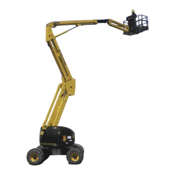
Page 11: Location Of Main Components
1.9. Location of main components The picture shows the machine and its own components. Control panel Electric control unit Hydraulic oil tank 1-13-18 Diesel tank (models "D") Diesel Engine (models "D") Drive pump Movement pump 12V emergency electrical pump (optional on models “D”) 380V three-phase electrical pump (optional) 10) Hydraulic drive motors... -
Page 12: Technical Features Of Standard Machines
TECHNICAL FEATURES OF STANDARD MACHINES THE TECHNICAL FEATURES OF THE PRODUCTS IN THE FOLLOWING PAGES CAN BE MODIFIED WITHOUT PRIOR NOTICE 2.1. Model A21 JRTD A21 JRTD Dimensions: Maximum working height 20.55 67’ 5” Max. platform height 18.55 60’ 10” Ground clearance 1.6”... - Page 13 Battery power: Battery capacity and voltage V/Ah V/Ah Battery weight Single-phase battery charger (HF) Max. current absorbed by the battery charger Max. installed power Electrical pump power 1 Max. absorbed current Power electric pump 2 Max. absorbed current Power electric pump 3 Max.
-
Page 14: Model A21 Jrte
2.2. Model A21 JRTE A21 JRTE Dimensions: Maximum working height 20.55 67’ 5” Max. platform height 18.55 60 ‘10” Ground clearance 1.6” Max. outreach from turntable centre 11.3 37” Turret rotation (continuous) ° ° Platform rotation ° ° Platform height for safety speed activation <... - Page 15 Diesel Power HATZ Diesel engine type Motor power Starter battery V/Ah V/Ah Diesel oil tank capacity Diesel Power ISUZU Diesel engine type Motor power Starter battery V/Ah V/Ah Diesel oil tank capacity 380V three-phase electrical pump (optional) Motor power Max. absorbed current Max.
- Page 16 A 2 1 J R T D A 2 1 J R T E Use and Maintenance Manual – A21 J A23 J Series Page 16...
-
Page 17: Model A23 Jrtd
2.3. Model A23 JRTD A23 JRTD Dimensions: Maximum working height 23.1 75’ 9” Max. platform height 21.1 69‘ 2” Ground clearance 1’ 6” Max. outreach from turntable centre 13.9 45’ 7” Turret rotation (continuous) ° ° Platform rotation ° ° Platform height for safety speed activation <... - Page 18 Diesel Power HATZ Diesel engine type HATZ HATZ 3L41C 3L41C Max. motor power 38.8 52.0 Adjusted Power 35.5 47.6 Starter battery V/Ah 12 / 12 / 180 V/Ah Total electrolyte quantity Diesel oil tank capacity 18.4 Diesel Power ISUZU Diesel engine type ISUZU ISUZU 4LE1 4LE1...
-
Page 19: Model A23 Jrte
2.4. Model A23 JRTE A23 JRTE Dimensions: Maximum working height 23.1 75’ 9” Max. platform height 21.1 69 ‘2” Ground clearance 18.8” Max. outreach from turntable centre 13.9 45 ‘6” Turret rotation (continuous) ° ° Platform rotation ° ° Platform height for safety speed activation <... - Page 20 Diesel Power HATZ Diesel engine type Motor power Starter battery V/Ah V/Ah Diesel oil tank capacity Diesel Power ISUZU Diesel engine type Motor power Starter battery V/Ah V/Ah Diesel oil tank capacity 380V three-phase electrical pump (optional) Motor power Max. absorbed current Max.
- Page 21 A 2 3 J R T D A 2 3 J R T E Use and Maintenance Manual – A21 J A23 J Series Page 21...
-
Page 22: Vibrations And Noise
2.5. Vibrations and noise Noise tests have been carried out under the most unfavourable conditions to study the effects on the operator. The level of acoustic pressure weighed (A) at work places does not exceed 70dB(A) for each electrical models. For the Diesel engine models, the level of acoustic pressure weighed (A) at work places does not exceed 106dB(A), the level of acoustic pressure at ground control panel does not exceed 85dB(A), the level of acoustic pressure at platform control panel does not exceed 78bD(A). -
Page 23: Safety Precautions
SAFETY PRECAUTIONS 3.1. Personal protective equipment (PPE) Always wear personal protective equipment according to current regulations concerning industrial health and safety (in particular, hard hat and safety shoes are COMPULSORY). It is the operator or safety manager’s responsibility to choose the personal protective equipment (PPE) depending on the activity to be carried out. -
Page 24: Use Instructions
3.3. Use instructions 3.3.1. General The electric and hydraulic circuits are provided with safety devices, calibrated and sealed by the manufacturer: DO NOT TAMPER WITH AND MODIFY THE CALIBRATION OF ANY COMPONENT OF THE ELECTRIC AND HYDRAULIC SYSTEMS. The machine must be used only in areas well lit up, checking that the ground is flat and firm. The machine may not be used if the lighting conditions are not sufficient. - Page 25 Check that in the operating area there are not obstacles or other dangerous elements. Pay particular attention to the area above the machine during lifting to avoid any crushing and collisions. During operation keep your hands in safety position, the driver has to place them as shown in picture A or B while the transported operator has to keep them as shown in picture C.
-
Page 26: Operating Procedures
3.3.3. Operating procedures The machine is equipped with a chassis inclination control system disabling lifting operations in case of unstable positioning. Working operations can be resumed only after placing the machine in a steady position. If the audible alarm and the red light on the platform control panel turn on, the machine is not correctly positioned (see paragraphs relevant to “Use instructions”). -
Page 27: Wind Speed According To Beaufort Scale
3.3.4 Wind speed according to Beaufort scale You can use the table below for a simple assessment of the wind speed. We remember that the max. limit for each machine model is indicated in the table TECHNICAL FEATURES OF STANDARD MACHINES. The machines for which the max. -
Page 28: Pressure Of The Machine On Ground And Load-Bearing Capacity Of Ground
3.3.5 Pressure of the machine on ground and load-bearing capacity of ground Before using the machine, the operator must make sure the floor is suitable for withstanding the specific loads and pressures on the ground with a certain safety margin. The following chart provides the parameters in play and two examples of calculation of the average pressure on the ground below the machine and max pressure underneath the wheels or stabiliser outriggers (p1 and p2). -
Page 29: High-Voltage Power Lines
The table below shows the load-bearing capacity of the ground split up by ground type. Refer to the data contained in the specific tables of each model (chapter 2, TECHNICAL FEATURES OF STANDARD MACHINES) to obtain the figure relating to the max pressure on the ground caused by the single wheel. Using the machine is forbidden if the max pressure on the ground per wheel is above the load-bearing capacity of the specific type of ground on which the machine is to be used. -
Page 30: Installation And Preliminary Checks
INSTALLATION AND PRELIMINARY CHECKS The machine is supplied completely assembled, therefore it can perform all functions in full safety as provided for by the manufacturer. No preliminary operation is required. To unload the machine, follow the instructions in chapter “Handling and carrying”. -
Page 31: How To Use
HOW TO USE Before using the machine read this chapter thoroughly. WARNING! Follow exclusively the instructions given in the next paragraphs and the safety rules described both hereafter and in the previous paragraphs. Read the next paragraphs carefully in order to properly understand the on/off procedures as well as all operations and their correct use. - Page 32 Power selector: Diesel/Electrical or Electrical DC (48Vdc battery)/Electrical AC (mains) Electric power selector 12V (Battery) or 380V (three-phase mains) – if both installed – O) Starter button electrical pump 12V (Battery) or 380V (three-phase mains) – if both installed – Electrical pump starter button 12V (Battery) or 380V (three-phase mains) –...
-
Page 33: Drive And Steering
5.1.1. Drive and steering Before carrying out any displacement operation, verify that no people are in proximity of the machine and in any case proceed with the utmost caution. IT IS FORBIDDEN to drive the machine when the platform is lifted unless the chassis is flat and steady with no holes and steps. - Page 34 NOTE FOR MACHINES WITH OSCILLATING AXLE: A sensor controls the swinging of the oscillating axle. With platform raised (booms up and jib at a height over +10° with respect to the horizontal axis) if the wheels of the oscillating axle are not on the same ideal plane as those of the fixed axle (with some tolerance) drive is prevented and a red light will turn on to warn of this condition (ZC).
-
Page 35: Platform Positioning Movements
5.1.2. Platform Positioning Movements To carry out all movements other than drive, use proportional levers B, C, D, E, F, G, H and switches I and L. To achieve the movement it is necessary to carry out the following operations in sequence: a) Press dead-man pedal located on the platform;... -
Page 36: Telescopic Boom Extension/Retraction
5.1.2.4. Telescopic boom extension/retraction To extend/retract the telescopic boom, use the proportional lever E. Set the proportional lever E forward for extension or backward for retraction. This manoeuvre does not work while turret rotation is taking place. 5.1.2.5. QUICK UP/QUICK DOWN (OPTIONAL) This lever controls the quick lifting/lowering of the platform, while simultaneously controlling the following manoeuvres: Pantograph lifting/lowering. -
Page 37: Platform Rotation
5.1.2.8. Platform rotation To rotate the platform, use the switch l. Set the switch I on the right for right rotation, or on the left for left rotation. This manoeuvre cannot be carried out when other operations are taking place. 5.1.2.9. -
Page 38: Other Functions Of The Platform Control Panel
5.1.3. Other functions of the platform control panel 5.1.3.1. Electric/thermic power selection, electrical ac/electrical dc On a few models the type of power can be selected using the selector M. On models equipped with heat engine, set it to Electric position to use the electric power (12V battery for boom emergency operations or 380V three-phase for boom work operations - OPTIONAL);... -
Page 39: Manual Horn
5.1.3.6. Manual horn The horn warns that the machine is moving; press button S to activate it. 5.1.3.7. Emergency stop button By pressing the red emergency STOP R button all control functions are stopped. Normal functions are enabled by rotating the button of 1/4 turn clockwise. -
Page 40: Danger Red Warning Light (Zd)
(pedal, joystick control, switches, etc). It flashes with a series of three flashes If the platform when the chains of extraction and/or retraction are slackened or faulty ( A23 J ONLY). -
Page 41: Ground Control Panel (Electric Control Unit)
5.2. Ground control panel (electric control unit) The ground control panel (or electric control unit) contains the main electronic boards necessary to operate the machine and to carry out safety checks. The ground control panel is located on the rotating turret (see paragraph "Location of main components") and is used to: Turn the machine ON/OFF. -
Page 42: On-Off Key And Control Panel Selector (A)
A) ON-OFF key and ground/platform control panel selector B) Emergency STOP button C) Selector for Diesel power for work or 12V electric power for emergency operations D) Heat engine start button (models “D” and “ED”) E) User interface display F) Battery charger warning light (models “E” and “ED”) G) Powered-on machine warning light H) Alternator warning light (models “D”... -
Page 43: User Interface Display (E)
5.2.5. User interface display (E) The multifunction display for machine/user interface is used to: Display the operation parameters of the machine during normal functioning or in the event of a fault. Working hours of Diesel engine (when Diesel power is selected the working hours are displayed in the format HOURS: MINUTES and final letter D). -
Page 44: Platform Access
5.3. Platform access The “access position” is the only one from which loading or unloading of persons and materials is allowed. The “access position” to the work platform is the completely lowered configuration. To get on the platform: Get on the platform hanging on to the entry guard rails. -
Page 45: Diesel Engine Start-Up
On dual propulsion models (Electric/Diesel) (models “ED” or “EB”), it is necessary to select the power supply type by means of the selector. To use the electric drive power once this option has been selected the operator can start performing the various functions by following the instructions given in the previous paragraphs. To use the thermic drive power read the next paragraphs to start the heat engine. -
Page 46: Start-Up Of 380V Work Electrical Pump (Optional)
5.4.2. Start-up of 380V work electrical pump (OPTIONAL) Both Diesel-powered and 48Vdc battery powered models can be equipped, on request, with a 380V three-phase electric pump for the operations of the booms (lifting, lowering, rotation). To start the three-phase electrical pump: Insert the 380 V plug of the power cable into socket (A) on the chassis. -
Page 47: Start-Up Of 12V Emergency Electric Pump (Optional For Models "D")
5.4.3. Start-up of 12V emergency electric pump (OPTIONAL for models “D”) Diesel power models are equipped with a 12V electrical pump for the operation of the booms (lifting, lowering, rotation) in the event of an emergency. To start the emergency electrical pump by means of the platform control panel: Select the platform control panel with the locking key switch on the ground control unit. -
Page 48: Machine Stop
5.5. Machine stop 5.5.1. Normal stop In normal operating conditions: By releasing the controls the operation is stopped. Stop occurs within a time limit set in the factory, which guarantees smooth braking. By releasing the dead-man pedal located on the platform, the operation is immediately stopped. In the event of an immediate stop, braking is sudden. -
Page 49: Stopping The 380V Three-Phase Or 230V Single-Phase Electrical Pump (Optional)
5.5.4. Stopping the 380V three-phase or 230V single-phase electrical pump (optional) To stop the electrical pump (optional): On the platform control panel: Press the stop button. Otherwise, press the emergency stop button. On the ground control panel: Press the emergency stop button. Use and Maintenance Manual –... -
Page 50: Emergency Manual Controls
5.6. Emergency manual controls This function is to be used only in emergency situations, when no motive power is available. fig. 11 In case of fault in the electric or hydraulic system, carry out the following emergency procedures: 1) Screw the read tap completely (behind solenoid valve EV11). 2) Screw the knurled knob of the solenoid valve corresponding to the desired movement. -
Page 51: Socket For Electric Tool Connection (Optional)
WARNING: The emergency control can be stopped at any moment by releasing the knob or by stopping the pump. Once this emergency manoeuvre has been carried out, the knurled knobs and the tap must be set to their initial position again in order to resume the operations (in normal position the knobs are completely unscrewed). -
Page 52: End Of Work
5.9. End of work After stopping the machine according to the instructions given in the previous paragraphs: Always set the machine to rest position (platform completely lowered). Press the emergency Stop button on the ground control panel. Remove the keys from the control panel to prevent unauthorized people from using the machine. Recharge the battery according to the instructions given in section "Maintenance"... -
Page 53: Handling And Carrying
HANDLING AND CARRYING 6.1. Handling Before using the machine, make sure that the mechanical lock device of the turret is disabled (see figure aside). To handle the machine in normal operating conditions follow the instructions given in chapter "USE INSTRUCTIONS" under paragraph "Drive and steering”. -
Page 54: Carrying
6.2. Carrying In order to carry the machine to the various working sites, follow the instructions given below. Considering the large dimensions of some models, before carrying, it is recommended to inquire about the overall dimension limits for road transport in force in your country. Before carrying the machine, turn it off and remove the keys from the control panels. - Page 55 Should these stickers be not available, DO NOT lift the machine by means of a lift truck. Lifting the machine by means of a lift truck is a dangerous operation, which must be carried out by qualified operators only. After placing the machine onto the carrying vehicle, fasten it by means of the same holes used for lifting.
-
Page 56: Emergency Towing Of The Machine
6.3. Emergency towing of the machine In the event of a fault, carry out the following operations to tow the machine: Hook the machine to the provided holes. Loosen the three fixing screws of the central covers of all drive reduction gears (the reduction gears are 2 if the machine has two driving wheels or 4 if it has four driving wheels). -
Page 57: Maintenance
The maintenance operations described below refer to a machine with ordinary working use. In case of difficult conditions of use (extreme temperatures, corrosive environments, etc.) or following long machine inactivity, it will be necessary to contact the AIRO assistance service to change the intervention schedule. -
Page 58: General Maintenance
7.2. General maintenance Below are listed the main maintenance jobs to be done and the relevant schedule (the machine features an hour meter). Operation Frequency Screw tightening (see paragraph "Various adjustments") After the first 10 working hours Oil level check in hydraulic tank After the first 10 working hours Check of the battery state (charge and liquid level) Every day... -
Page 59: Various Adjustments
7.2.1. Various adjustments Check the conditions of the following components and, necessary, tighten after the first 10 working hours and, afterwards, at least once a year: 1) Wheel screws 2) Drive motor fixing screws 3) Steering cylinder fixing screws 4) Fixing screws of steering hub pins 5) cage fixing screws 6) Hydraulic fittings... -
Page 60: Greasing
7.2.2. Greasing Grease all articulated joints equipped with greaser (or predisposition for greaser) at least every month. At least once a month, using a spatula or a brush, lubricate the telescopic extension. Moreover, always remember to grease the articulated joints: After washing the machine. -
Page 61: Hydraulic Circuit Oil Level Check And Change
7.2.3. Hydraulic circuit oil level check and change Check after the first 10 working hours and, afterwards, once a month the level by means of the provided indicator (detail A in the picture aside) and make sure that the level always lies between the max. -
Page 62: Biodegradable Hydraulic Oil (Optional)
Do not dispose of used oil in the environment. Comply with the current local standards. The lubricants, hydraulic oils, electrolytes and all detergent products should be handled with care and disposed of in safety according to the current regulations. A prolonged contact with the skin may cause irritations and dermatosis; wash with water and soap and rinse thoroughly. -
Page 63: Mix
The fluid state is therefore constantly monitored, thus allowing its use until its features decay. Normally, in the absence of contaminating agents, the oil is never completely changed, but only occasionally topped-up. The oil samples (at least 500ml) must be taken with the system at operating temperature. It is recommended to use new and clean containers. -
Page 64: Hydraulic Filter Replacement
7.2.4. Hydraulic filter replacement 7.2.4.1. Suction filters 7.2.4.1.1. Main gear pump filter All models are equipped with a suction filter installed inside the tank at the base of the suction tube, which has to be replaced at least every two years. To replace the suction filters installed inside the tank (see figure): Stop the machine by pressing the emergency... -
Page 65: Filter Of Electrical Pumps, 380V (Optional) And 12V (Emergency On Diesel Models)
7.2.4.1.2. Filter of electrical pumps, 380V (OPTIONAL) and 12V (emergency on Diesel models) The models equipped with a 380V electrical pump (OPTIONAL) and/or a 12V emergency pump have an extra suction filter inside the suction tube, which has to be replaced at least every two years. To replace the suction filters installed inside the tank (see figure): Stop the machine by pressing the emergency... -
Page 66: Return Filter
7.2.4.2. Return filter The return filter directly flanged on the tank is equipped with a visual clogging indicator. During normal operation, the visual indicator is in the green zone. When the indicator is in the red zone, the filtering cartridge is to be replaced. -
Page 67: Turret Rotation Reduction Gear Oil Level Check And Change
7.2.5. Turret rotation reduction gear oil level check and change The oil level should be checked at least once a year. Check the level by means of cap (A). Oil check must be carried out when the oil is hot. The level is correct when the reduction gear body is full of oil up to the cap limit. -
Page 68: Drive Reduction Gear Oil Level Check And Change
7.2.6. Drive reduction gear oil level check and change The oil level should be checked at least once a year. Position the machine until the two caps (A and B) reach the position indicated in the picture aside. Check the level by means of cap (A). -
Page 69: Air Purging From Oscillating Axle Locking Cylinders
7.2.7. Air purging from oscillating axle locking cylinders Once drive has been stopped and with raised platform, the axle locking cylinders are locked in position thus increasing the machine stability. Check that no air is present inside the oscillating axial cylinders every year. -
Page 70: Turret Rotation Clearance Adjustment
7.2.8. Turret rotation clearance adjustment Check the coupling between the rotation pinion and the turntable should be carried out every year. In normal operating conditions, the coupling clearance must be minimum. Otherwise, adjust according to the following instructions: Unscrew the four cylinder head screws (A) which fix the reduction gear support to the turret. -
Page 71: Visual Check Of Wear Condition Of Chains Of Boom Extraction (A23 J Only)
7.2.10. Visual check of wear condition of chains of boom extraction (A23 J only) Every year check the wear condition of chains of extraction of the telescopic boom. The type of chain used is Fleyer BL466, the pitch 12.7 mm (*). The check is to be carried out by measuring 10 pitches. -
Page 72: Check/Adjustment Of Tension Of Chains Of Telescopic Boom Extraction (A23 J Only)
7.2.11. Check/adjustment of tension of chains of telescopic boom extraction (A23 J only) Every year check the tension of chains of the telescopic boom extraction. The correct tension is achieved when the two telescopic deck extensions start simultaneously during extraction (or retraction). -
Page 73: Circuit Movements Pressure Relief Valve Operation Check
7.2.12. Circuit movements pressure relief valve operation check The main pressure relief valve controls the maximum pressure of the circuit movements. (lifting operations/lowering/rotation). Normally, this valve does not require any adjustment, since it is calibrated at the factory before the machine is delivered. -
Page 74: Operation Check Of The Turret Inclinometer
7.2.13. Operation check of the turret inclinometer WARNING! Usually the inclinometer does not need to be adjusted unless the electronic control unit is replaced. The equipment necessary for the replacement and adjustment of this component is such that these operations should be carried out by skilled personnel. AS THIS OPERATION IS VERY IMPORTANT IT IS TO BE CARRIED OUT BY SKILLED TECHNICIANS ONLY. - Page 75 If the alarm does not go off CALL THE TECHNICAL ASSISTANCE. MODELS SHIMS A21 JRTD A21 JRTE A23 JRTD A23 JRTE A [mm] B [mm] WARNING! The dimensions of shims A and B refer to max. allowed inclination as indicated in table “TECHNICAL FEATURES”.
-
Page 76: Operation Check And Adjustment Of Platform Overload Controller
7.2.14. Operation check and adjustment of platform overload controller The AIRO self-propelled articulated boom aerial platforms are equipped with a sophisticated overload controller. Normally the overload controller does not require any adjustments, since it is calibrated in the factory before the machine is delivered. - Page 77 Calibration depends on the type of fitted device. If the board is the one shown in fig.31a: Switch off the machine. Open the box which contains electronic board C. Without any load on the platform, fit the bridge between the two pins of the connector G. Switch on the machine.
-
Page 78: Overload Controller By-Pass - Only For Emergency Operations
7.2.15. Overload controller by-pass – ONLY FOR EMERGENCY OPERATIONS In case of fault and impossibility to calibrate the device, a by-pass of the system is possible by means of locking key switch (A) under the control panel. Keep the locking key switch active for 5 seconds and release to get the BY-PASS condition. -
Page 79: Operation Check Of M1 Microswitches
7.2.16. Operation check of M1 microswitches The lifting booms and the telescopic extraction are controlled by microswitches: M1A on the pantograph. M1B on the boom. M1C on the Jib. M1D on the telescopic extraction. Once a year check the working conditions of the microswitches M1. The functions of the microswitches M1A- M1B- M1BB are the following: with platform not in rest position (at least one of the microswitches... -
Page 80: Operation Check Of Microswitch M9 (Optional)
7.2.17. Operation check of microswitch M9 (OPTIONAL) The position of the swinging turret with respect to the chassis can be controlled by the microswitch M9 (OPTIONAL). This microswitch at the centre of the turret will allow the operator on board to have the drive and steer direction always consistent with the platform position. -
Page 81: Operation Check Of Proximity Sensors M11 And M12 (Optional)
7.2.19. Operation check of proximity sensors M11 and M12 (OPTIONAL) The proximity sensors M11 and M12 (OPTIONAL) control the positioning of the 4 steering wheels (OPTIONAL). The presence of the sensors M11 and M12 is tied to the option “4WS”. The sensors are located: One on the front steering axle. -
Page 82: Operation Check Of Dead-Man Pedal Safety System
7.2.22. Operation check of dead-man pedal safety system The platform dead-man pedal is for enabling the operation controls of the machine on the platform control panel. Check operation at least once a year. To check the dead-man PEDAL: Move the drive joystick forward and backward in sequence, WITHOUT PRESSING THE dead-man PEDAL. Check that the machine does not perform any movement. -
Page 83: Starting Battery
7.3. Starting battery The battery is one of the most important elements of the machine. It is recommended to keep it in an efficient condition to increase its useful life, to avoid faults and to reduce the management costs of the machine. 7.3.1. -
Page 84: Drive" Battery For Models "E" And "Ed
7.4. “DRIVE” battery for models “E” and “ED” The battery is one of the most important elements of the machine. It is recommended to keep it in an efficient condition to increase its useful life, to avoid faults and to reduce the management costs of the machine. 7.4.1. -
Page 85: Battery Charger: Drive Battery Recharge
7.4.3. Battery charger: DRIVE battery recharge WARNING! EXPLOSIVE gas is originated during battery charging process. Therefore, charging must take place in airy rooms where no risks of fire and explosion exist and in the presence of fire extinguishers. Connect the battery charger to the power mains having all protections according to the current standards in force and with the following features: Power voltage 380V 380V (400V +/-15%) 50Hz/60Hz. -
Page 86: Battery Charger: Fault Report
Set the on-off switch C of the ground control station to OFF position (machine off), checking battery charger connection by means of LED D (red) (if it is on, connection is on-line). If led E (yellow) lights up, battery charger is approximately 80%. If led Led F (green) lights up, battery charge is over;... - Page 87 AS THIS OPERATION IS VERY IMPORTANT IT IS TO BE CARRIED OUT BY SKILLED TECHNICIANS ONLY. CALL THE TECHNICAL SUPPORT Use and Maintenance Manual – A21 J A23 J Series Page 87...
-
Page 88: Marks And Certifications
MARKS AND CERTIFICATIONS The models of self-propelled aerial platform described in this manual were subjected to the CE type test according to the Directive 2006/42/EC. The certification was issued by: ICE Spa Via Garibaldi, 20 40011 Anzola Emilia – BO (Italy) Test carrying out is shown by the above plate with CE mark applied on the machine and by the declaration of conformity enclosed in this user manual. -
Page 89: Plates And Stickers
23** 001.10.098 STOP sticker I-D-F-NL-B-GB 24** 001.10.242 Emergency stop button yellow sticker 001.10.175 AIRO pre-spaced yellow sticker <530x265> 035.10.023 Pre-spaced sticker A21 JRTE BLACK 035.10.024 Pre-spaced sticker A21 JRTD BLACK 036.10.007 Pre-spaced sticker A23 JRTD BLACK 036.10.008 Pre-spaced sticker A23 JRTE BLACK 27*** 045.10.010... - Page 90 Use and Maintenance Manual – A21 J A23 J Series Page 90...
-
Page 91: 0 . Check Register
1 0 . CHECK REGISTER The check register is released to the user of the platform in conformance with annex 1 of Directive 2006/42/EC. This register is to be considered an integral part of the equipment and must accompany the machine for its entire life until its final disposal. - Page 92 REQUIRED PERIODIC INSPECTIONS BY THE REGULATORY AGENCY Date Observations Signature + Stamp Use and Maintenance Manual – A21 J A23 J Series Page 92...
- Page 93 REQUIRED PERIODIC INSPECTIONS BY THE OWNER STRUCTURAL CHECK DESCRIPTION OF OPERATIONS TO BE PERFORMED Check the integrity of the guardrails; the harness anchoring points; any access ladders; state of the lifting structure; rust; state of the VISUAL CHECK tyres; oil leaks; locking pins on the structure. DATE REMARKS SIGNATURE + STAMP...
- Page 94 REQUIRED PERIODIC INSPECTIONS BY THE OWNER STRUCTURAL CHECK DESCRIPTION OF OPERATIONS TO BE PERFORMED VARIOUS ADJUSTMENTS See chapter 7.2.1 DATE REMARKS SIGNATURE + STAMP 1st YEAR 2nd YEAR 3rd YEAR 4th YEAR 5th YEAR 6th YEAR 7th YEAR 8th YEAR 9th YEAR 10th YEAR See chapter 7.2.2...
- Page 95 REQUIRED PERIODIC INSPECTIONS BY THE OWNER CHECK DESCRIPTION OF OPERATIONS TO BE PERFORMED See chapter 7.2.3. HYDRAULIC TANK OIL LEVEL Daily operation. It is not necessary to indicate its execution every day, CHECK but at least every year when the other operations are carried out. DATE REMARKS SIGNATURE + STAMP...
- Page 96 REQUIRED PERIODIC INSPECTIONS BY THE OWNER CHECK DESCRIPTION OF OPERATIONS TO BE PERFORMED CALIBRATION CHECK OF MOVEMENT CIRCUIT RELIEF See chapter 7.2.12 PRESSURE VALVE DATE REMARKS SIGNATURE + STAMP 1st YEAR 2nd YEAR 3rd YEAR 4th YEAR 5th YEAR 6th YEAR 7th YEAR 8th YEAR 9th YEAR...
- Page 97 REQUIRED PERIODIC INSPECTIONS BY THE OWNER CHECK DESCRIPTION OF OPERATIONS TO BE PERFORMED See chapter 7.3 and 7.4. BATTERY STATE Daily operation. It is not necessary to indicate its execution every day, but at least every year when the other operations are carried out. DATE REMARKS SIGNATURE + STAMP...
- Page 98 REQUIRED PERIODIC INSPECTIONS BY THE OWNER CHECK DESCRIPTION OF OPERATIONS TO BE PERFORMED TOTAL OIL CHANGE IN THE HYDRAULIC TANK FROM DRIVE See chapters 7.2.3, 7.2.5, 7.2.6 AND ROTATION REDUCTION GEARS (EVERY TWO YEARS) DATE REMARKS SIGNATURE + STAMP 2nd YEAR 4th YEAR 6th YEAR 8th YEAR...
- Page 99 REQUIRED PERIODIC INSPECTIONS BY THE OWNER CHECK DESCRIPTION OF OPERATIONS TO BE PERFORMED AIR PURGING FROM OSCILLATING See chapter 7.2.7. AXLE CYLINDERS DATE REMARKS SIGNATURE + STAMP 1st YEAR 2nd YEAR 3rd YEAR 4th YEAR 5th YEAR 6th YEAR 7th YEAR 8th YEAR 9th YEAR 10th YEAR...
- Page 100 REQUIRED PERIODIC INSPECTIONS BY THE OWNER SAFETY SYSTEM CHECK DESCRIPTION OF OPERATIONS TO BE PERFORMED OPERATION CHECK OF THE See chapter 7.2.13 TURRET INCLINOMETER DATE REMARKS SIGNATURE + STAMP 1st YEAR 2nd YEAR 3rd YEAR 4th YEAR 5th YEAR 6th YEAR 7th YEAR 8th YEAR 9th YEAR...
- Page 101 REQUIRED PERIODIC INSPECTIONS BY THE OWNER SAFETY SYSTEM CHECK DESCRIPTION OF OPERATIONS TO BE PERFORMED VISUAL CHECK OF WEAR CONDITION OF CHAINS OF BOOM See chapter 7.2.10 EXTRACTION/BOOM RETRACTION (A23 J ONLY) DATE REMARKS SIGNATURE + STAMP 1st YEAR 2nd YEAR 3rd YEAR 4th YEAR 5th YEAR...
- Page 102 REQUIRED PERIODIC INSPECTIONS BY THE OWNER SAFETY SYSTEM CHECK DESCRIPTION OF OPERATIONS TO BE PERFORMED EFFICIENCY CHECK OF PLATFORM See chapter 7.2.14 OVERLOAD CONTROLLER DATE REMARKS SIGNATURE + STAMP 1st YEAR 2nd YEAR 3rd YEAR 4th YEAR 5th YEAR 6th YEAR 7th YEAR 8th YEAR 9th YEAR...
- Page 103 REQUIRED PERIODIC INSPECTIONS BY THE OWNER SAFETY SYSTEM CHECK DESCRIPTION OF OPERATIONS TO BE PERFORMED OPERATION CHECK MICROSWITCH See chapter 7.2.17 DATE REMARKS SIGNATURE + STAMP 1st YEAR 2nd YEAR 3rd YEAR 4th YEAR 5th YEAR 6th YEAR 7th YEAR 8th YEAR 9th YEAR 10th YEAR...
- Page 104 REQUIRED PERIODIC INSPECTIONS BY THE OWNER SAFETY SYSTEM CHECK DESCRIPTION OF OPERATIONS TO BE PERFORMED OPERATION CHECK PROXIMITY See chapter 7.2.19 SENSOR M10 and M!" DATE REMARKS SIGNATURE + STAMP 1st YEAR 2nd YEAR 3rd YEAR 4th YEAR 5th YEAR 6th YEAR 7th YEAR 8th YEAR...
- Page 105 REQUIRED PERIODIC INSPECTIONS BY THE OWNER SAFETY SYSTEM CHECK DESCRIPTION OF OPERATIONS TO BE PERFORMED OPERATION CHECK OPERATION CHECK OF MICROSWITCHES M15 See chapter 7.2.21 AND M14 (A23 J ONLY) DATE REMARKS SIGNATURE + STAMP 1st YEAR 2nd YEAR 3rd YEAR 4th YEAR 5th YEAR 6th YEAR...
- Page 106 REQUIRED PERIODIC INSPECTIONS BY THE OWNER SAFETY SYSTEM CHECK DESCRIPTION OF OPERATIONS TO BE PERFORMED DEAD-MAN SYSTEM CHECK See chapter 7.2.22 DATE REMARKS SIGNATURE + STAMP 1st YEAR 2nd YEAR 3rd YEAR 4th YEAR 5th YEAR 6th YEAR 7th YEAR 8th YEAR 9th YEAR 10th YEAR...
- Page 107 REQUIRED PERIODIC INSPECTIONS BY THE OWNER CHECK OF EMERGENCY DEVICES DESCRIPTION OF OPERATIONS TO BE PERFORMED MANUAL EMERGENCY LOWERING See chapter 5.6 CHECK DATE REMARKS SIGNATURE + STAMP 1st YEAR 2nd YEAR 3rd YEAR 4th YEAR 5th YEAR 6th YEAR 7th YEAR 8th YEAR 9th YEAR...
- Page 108 COMPANY DATE MODEL SERIAL NUMBER DELIVERY DATE AIRO – Tigieffe S.r.l. SUBSEQUENT TRANSFERS OF OWNERSHIP COMPANY DATE We affirm that, as of the date quoted above, the technical, dimensional and functional features of this machine were in conformance with what was originally required and that any changes have been recorded in this Register.
- Page 109 SUBSEQUENT TRANSFERS OF OWNERSHIP COMPANY DATE We affirm that, as of the date quoted above, the technical, dimensional and functional features of this machine were in conformance with what was originally required and that any changes have been recorded in this Register. THE SELLER THE PURCHASER SUBSEQUENT TRANSFERS OF OWNERSHIP...
- Page 110 IMPORTANT BREAKDOWNS DATE DESCRIPTION OF BREAKDOWN SOLUTION SPARE PARTS USED DESCRIPTION CODE QUANTITY SERVICE SAFETY MANAGER DATE DESCRIPTION OF BREAKDOWN SOLUTION SPARE PARTS USED DESCRIPTION CODE QUANTITY SERVICE SAFETY MANAGER Use and Maintenance Manual – A21 J A23 J Series Page 110...
- Page 111 IMPORTANT BREAKDOWNS DATE DESCRIPTION OF BREAKDOWN SOLUTION SPARE PARTS USED DESCRIPTION CODE QUANTITY SERVICE SAFETY MANAGER DATE DESCRIPTION OF BREAKDOWN SOLUTION SPARE PARTS USED DESCRIPTION CODE QUANTITY SERVICE SAFETY MANAGER Use and Maintenance Manual – A21 J A23 J Series Page 111...
-
Page 112: Wiring Diagrams
11. W IRING DIAGRAMS A21 JRTE A21 JRTE A21 JRTD A21 JRTD ELECTRIC Macchina / Machine ELECTRIC DIESEL DIESEL A23 JRTE A23 JRTD A23 JRTD A23 JRTE Codice / Code Descrizione / Description ELECTRIC ELECTRIC DIESEL DIESEL 4WS Chassis junction box - wired 035.08.028 4WS fixed structure derivation box - cabled... - Page 113 035.08.028 Use and Maintenance Manual – A21 J A23 J Series Page 113...
- Page 114 035.08.050 Use and Maintenance Manual – A21 J A23 J Series Page 114...
- Page 115 035.08.017 Use and Maintenance Manual – A21 J A23 J Series Page 115...
- Page 116 035.08.025 Use and Maintenance Manual – A21 J A23 J Series Page 116...
- Page 117 035.08.072 Use and Maintenance Manual – A21 J A23 J Series Page 117...
- Page 118 035.08.034 Use and Maintenance Manual – A21 J A23 J Series Page 118...
- Page 119 035.08.069 Use and Maintenance Manual – A21 J A23 J Series Page 119...
- Page 120 035.08.053 Use and Maintenance Manual – A21 J A23 J Series Page 120...
- Page 121 035.08.068 Use and Maintenance Manual – A21 J A23 J Series Page 121...
- Page 122 035.08.024 Use and Maintenance Manual – A21 J A23 J Series Page 122...
- Page 123 Use and Maintenance Manual – A21 J A23 J Series Page 123...
-
Page 124: Hydraulic Diagram
12. H YDRAULIC DIAGRAM No. 035.07.086 DRIVE MOTOR REDUCER ROTATING DISTRIBUTOR FILTER QUICK COUPLING FILLER CAP COMBINED PUMP FILTER FILTER MANUAL PUMP EMERGENCY ELECTROPUMP STEERING CYLINDER STEERING HYDRAULIC BLOCK SWING AXLE CYLINDER 15-18-22-29 OVER-CENTER VALVE HYDRAULIC BLOCK STEERING SELECTION / MOVEMENTS MOVEMENT SOLENOID VALVE BLOCK SCISSOR CYLINDER TELESCOPIC BOOM EXTENSION CYLINDER... - Page 125 Use and Maintenance Manual – A21 J A23 J Series Page 125...
- Page 126 Use and Maintenance Manual – A21 J A23 J Series Page 126...
-
Page 127: Conformity Declaration
13. CONFORMITY DECLARATION AIRO è una Divisione TIGIEFFE SRL − Via Villa superiore, 82 −42045 Luzzara (RE) Tel. +39 0522 977365 Fax +39 0522 977015 DICHIARAZIONE CE DI CONFORMITA' - CE DECLARATION OF CONFORMITY - DECLARATION CE DE CONFORMITE' - EG KONFORMITÄTSERKLÄRUNG - DECLARACION CE DE CONFORMIDAD- ЗАЯВЛЕНИЕ... - Page 128 AIRO è una Divisione TIGIEFFE SRL − Via Villa superiore, 82 −42045 Luzzara (RE) Tel. +39 0522 977365 Fax +39 0522 977015 DICHIARAZIONE CE DI CONFORMITA' - CE DECLARATION OF CONFORMITY - DECLARATION CE DE CONFORMITE' - EG KONFORMITÄTSERKLÄRUNG - DECLARACION CE DE CONFORMIDAD- ЗАЯВЛЕНИЕ О КОНФОРМНОСТИ EC...
- Page 129 AIRO è una Divisione TIGIEFFE SRL − Via Villa superiore, 82 −42045 Luzzara (RE) Tel. +39 0522 977365 Fax +39 0522 977015 DICHIARAZIONE CE DI CONFORMITA' - CE DECLARATION OF CONFORMITY - DECLARATION CE DE CONFORMITE' - EG KONFORMITÄTSERKLÄRUNG - DECLARACION CE DE CONFORMIDAD- ЗАЯВЛЕНИЕ О КОНФОРМНОСТИ EC...
- Page 130 AIRO è una Divisione TIGIEFFE SRL − Via Villa superiore, 82 −42045 Luzzara (RE) Tel. +39 0522 977365 Fax +39 0522 977015 DICHIARAZIONE CE DI CONFORMITA' - CE DECLARATION OF CONFORMITY - DECLARATION CE DE CONFORMITE' - EG KONFORMITÄTSERKLÄRUNG - DECLARACION CE DE CONFORMIDAD- ЗАЯВЛЕНИЕ О КОНФОРМНОСТИ EC...
- Page 132 AIRO is a division of TIGIEFFE SRL Via Villasuperiore, 82 - 42045 Luzzara (RE) ITALIA- +39-0522-977365 - +39-0522-977015 WEB: www.airo.com – e-mail: info@airo.com...
Need help?
Do you have a question about the A Series and is the answer not in the manual?
Questions and answers