Sign In
Upload
Manuals
Brands
Airo Manuals
Boom Lifts
A Series
User Manuals: Airo A Series Self-propelled boom lift
Manuals and User Guides for Airo A Series Self-propelled boom lift. We have
4
Airo A Series Self-propelled boom lift manuals available for free PDF download: Use And Maintenance Manual
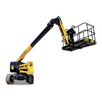
Airo A Series Use And Maintenance Manual (163 pages)
SELF-PROPELLED WORK-PLATFORMS
Brand:
Airo
| Category:
Boom Lifts
| Size: 7 MB
Table of Contents
Table of Contents
3
Introduction
7
Legal Aspects
7
Receiving of the Machine
7
Declaration of Commissioning, First Check, Further Periodical Checks and Transfers of Ownership
7
Declaration of Commissioning and First Check
7
Subsequent Periodic Checks
8
Transfers of Ownership
8
Education, Information and Operators Training
8
Tests Carried out Prior to Delivery by the Manufacturer
8
Intended Use
8
Leaving at Height
9
Description of the Machine
9
Control Panels
11
Power Supply
11
Machine Life, Demolition and Decommissioning
11
Identification
12
Location of Main Components
13
Technical Features of Standard Machines
14
A18 JRTD PLUS Model
14
Model A18 JRTH PLUS
16
A18 JRTE PLUS Model
19
Vibrations and Noise
22
Safety Precautions
23
Personal Protective Equipment (PPE)
23
General Safety Norms
23
Use Instructions
24
General
24
Handling
24
Operating Procedures
25
Wind Speed According to Beaufort Scale
26
Ground Pressure and Load-Bearing Capacity
27
High-Voltage Power Lines
28
Dangerous Situations And/Or Accidents
28
Installation and Preliminary Checks
29
Familiarisation
29
Preliminary Operation Checks
29
Use Instructions
30
Platform Control Panel
30
Drive
32
Steering
33
Platform Positioning Movements
34
Pantograph (Lower Boom) Up/Down
34
Upper Boom Up/Down
34
Jib Up/Down
34
Telescopic Boom In/Out
34
Quick Up/Quick down (Optional)
35
Turret Orientation (Rotation)
35
JIB Rotation (Optional)
35
Platform Rotation
35
Platform Levelling
35
Other Functions of the Platform Control Panel
36
Working Capacity Selector
36
FULL ELECTRIC / HYBRID AUTOMATIC Mode Selector (A18 JRTH Model)
36
Diesel Engine START/STOP Button
36
DIESEL Engine START/STOP for DIESEL Machines (A18 JRTD)
36
DIESEL Motor Generator START/STOP for HYBRID Machines (A18 JRTH)
36
Current Generator START/STOP Button for Power Line on the Platform
37
Current Generator START/STOP for DIESEL Machines (OPTIONAL for A18 JRTD)
37
Current Generator START/STOP for HYBRID Machines (Standard for A18 JRTH)
37
Emergency Electric Pump START/STOP Button (OPTIONAL)
37
Manual Horn
37
Emergency Stop
37
ETHERNET RJ45 Plug for Diagnostics and Calibration
37
USB Plug for Mobile Devices Charging (OPTIONAL)
37
Warning Lights
38
Enabled Control Panel Green Warning Light (ZA)
38
Low Battery Red Warning Light (ZB) - (A18 JRTH)
38
Diesel Engine Fault / Low Fuel Red Warning Light (ZC)
38
Danger Red Warning Light (ZD)
39
Overload Red Warning Light (ZE)
39
Reached Outreach Limit Red Warning Light (ZF)
39
Anti-Trapping System "AIRO SENTINEL" - OPTIONAL
40
SENTINEL Control Logic
41
Ground Control Panel and Electric Control Unit
42
On/Off Key and Control Panel Selector (A)
43
Emergency Stop Button (B)
43
User Interface Display (C)
44
Display Functions
44
Key Set on PLATFORM CONTROLS
45
Key Set on GROUND CONTROLS
47
Key Set on off with MAINS POWERED BATTERY CHARGER (A18 JRTH and A18 JRTE Models)
48
Key Set on UNATTENDED CHARGING by Motor Generator (A18 JRTH Models Only)
49
EMERGENCY OVERRIDE Activation Key (D)
50
Platform Access
51
Machine Start-Up
52
Diesel Motor Generator Start-Up (A18 JRTH Model)
52
Diesel Engine Start-Up (A18 JRTD Model)
52
Machine Stop
53
Normal Stop
53
Emergency Stop
53
Diesel Motor Generator Stop (A18 JRTH Model)
54
Diesel Engine Stop (A18 JRTD)
54
Emergency Manual Controls
55
Emergency Manual Control: Use of the Ground Control Panel
55
Emergency Manual Control: EMERGENCY OVERRIDE
55
Emergency Manual Controls: Manual Pump Activation
56
Socket for Electric Tool Connection (Optional)
58
115-230V Power Line from Diesel Generator (A18 JRTH Only)
58
115-230V Power Line from the Mains (Optional for A18 JRTD and A18 JRTE; Standard for A18 JRTH)
59
115-230V Power Line from Hydraulic Generator (Optional for A18 JRTD)
59
Fuel Level and Re-Fuelling
60
End of Work
60
Handling and Carrying
61
Handling
61
Transportation
62
Emergency Towing of the Machine
64
Maintenance
65
Machine Cleaning
65
General Maintenance
66
Greasing
66
Various Settings
67
Hydraulic Circuit Oil Level Check and Change
69
Biodegradable Hydraulic Oil (Optional)
70
Emptying
70
Filters
70
Washing
70
Filling
70
Commissioning / Check
70
Mixing
71
Microfiltration
71
Disposal
71
Topping up
71
Replacement of Hydraulic Filters
72
Suction Filters
72
Return Filter
72
Discharge Filter
73
Greasing the Turntable for Turret Rotation
74
Check Level and Replacement of Drive Axle Oil
75
Level Check and Oil Change from Electric Motor Reduction Gear (A18 JRTH PLUS and A18 JRTE PLUS Only)
76
Checks in the Use of Synthetic Biodegradable Oil in Drive Reduction Gears
77
Oscillating Axle Locking System Efficiency Check
78
Telescopic Boom Sliding Blocks Clearance Adjustment
79
Circuit Movements Pressure Relief Valve Operation Check
80
Proportional Movement Circuit Pressure Relief Valve
80
Pressure Relief Valve of the Circuit of ON-OFF Movements
81
Operation Check of the Turret Inclinometer
82
Adjustment of the Overload Controller (Load Cell)
84
Overload Controller By-Pass - ONLY for EMERGENCY OPERATIONS
85
Operation Check of M1 Microswitches
86
Check Operation of Proximity Sensors M2A + M2B - Turret Rotation Limit Switch
87
Operation Check of Dead-Man Pedal Safety System
88
Battery
89
Starter Battery (A18 JRTD PLUS and A18 JRTH PLUS Models)
89
Starter Battery Maintenance
89
Normal Charging of the Starter Battery
89
Emergency Charging of Starter Battery (A18 JRTD PLUS and A18 JRTH PLUS Models)
90
Starter Battery Replacement
90
Lithium Battery (A18 JRTH PLUS Model)
91
Lithium Battery General Warnings
91
Maintenance of the Lithium Battery
91
Recharging the Lithium Battery (A18 JRTH PLUS)
93
Charging by 115-230V Mains Current
93
Recharging by UNATTENDED CHARGING
94
Lead Acid Drive Battery (A18 JRTE PLUS Model)
95
Lead Acid Battery General Warnings
95
Lead Acid Battery Maintenance
96
Lead Acid Battery Charging
96
Battery Replacement (All Models)
98
Marks and Certifications
99
Plates and Stickers
100
Check Register
102
Wiring Diagrams
120
Wiring Diagram A18 JRTD PLUS - 078.08.028
120
Wiring Diagram A18 JRTH PLUS - 078.08.029
130
Wiring Diagram A18 JRTE PLUS - 078.08.057
141
Hydraulic Diagram
155
Hydraulic Diagram A18 JRTD PLUS - 078.07.001
155
Hydraulic Diagram A18 JRTH PLUS - A18 JRTE PLUS - 078.07.003
158
Declaration of Conformity Ec Facsimile
160
Advertisement
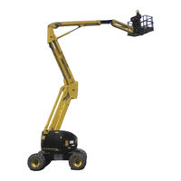
Airo A Series Use And Maintenance Manual (132 pages)
Self Propelled Work Platforms
Brand:
Airo
| Category:
Boom Lifts
| Size: 7 MB
Table of Contents
Table of Contents
3
1 Introduction
6
Legal Aspects
6
Delivery of the Machine
6
Declaration of Commissioning, First Check, Further Periodical Checks and Transfers of Ownership
6
Declaration of Commissioning and First Check
6
Further Periodical Checks
7
Transfers of Ownership
7
Operator Training and Information
7
Tests Performed before Delivery
7
Intended Use
7
Leaving at Height
8
Description of the Machine
8
Control Panels
9
Drive Power
9
Machine Life, Demolition and Decommissioning
9
Identification
10
Location of Main Components
11
2 Technical Features of Standard Machines
12
Model A21 Jrtd
12
Model A21 Jrte
14
Model A23 Jrtd
17
Model A23 Jrte
19
Vibrations and Noise
22
3 Safety Precautions
23
Personal Protective Equipment (Ppe)
23
General Safety Norms
23
Use Instructions
24
General
24
Handling
24
Operating Procedures
26
Wind Speed According to Beaufort Scale
27
Pressure of the Machine on Ground and Load-Bearing Capacity of Ground
28
High-Voltage Power Lines
29
Hazardous Situations And/Or Accidents
29
4 Installation and Preliminary Checks
30
Becoming Acquainted with the Machine
30
Preliminary Operation Checks
30
5 How to Use
31
Platform Control Panel
31
Drive and Steering
33
Platform Positioning Movements
35
Jib Lifting/Lowering
35
Pantograph (Lower Boom) Lifting/Lowering
35
Upper Boom Lifting/Lowering
35
Jib Rotation (OPTIONAL)
36
Quick Up/Quick down (Optional)
36
Telescopic Boom Extension/Retraction
36
Turret Orientation (Rotation)
36
Platform Levelling
37
Platform Rotation
37
Other Functions of the Platform Control Panel
38
Electric Power Selector 12V (Battery) or 230V/380V Three-Phase (Power Mains) - (OPTIONAL)
38
Electric/Thermic Power Selection, Electrical Ac/Electrical DC
38
Electrical Pump Start Button 12V (Battery) or 230V/380V Three-Phase Mains (Power Mains) - (OPTIONAL)
38
Heat Engine Start Switch ( "ED", "D" Models)
38
Three-Phase 380V Electric Pump Warning Light Lit up
38
Diesel Engine Fault / Low Fuel Red Warning Light (ZC)
39
Emergency Stop Button
39
Enabled Control Panel Green Warning Light (ZA)
39
Flat Battery Red Warning Light (ZB) - Electric Models Only
39
Manual Horn
39
Warning Lights
39
Danger Red Warning Light (ZD)
40
Overload Red Warning Light (ZE)
40
Ground Control Panel (Electric Control Unit)
41
On-Off Key and Control Panel Selector (A)
42
Emergency Stop Button (B)
42
Diesel/Electric Drive Power Selector (C)
42
Heat Motor Start Button (D)
42
User Interface Display (E)
43
Battery Charger Warning Light (F)
43
Enabled Control Panel Warning Light (G)
43
Diesel Engine Warning Lights (H L M N)
43
Platform Control Levers
43
Platform Access
44
Machine Start-Up
44
Diesel Engine Start-Up
45
Start-Up of 380V Work Electrical Pump (OPTIONAL)
46
Start-Up of 12V Emergency Electric Pump (OPTIONAL for Models "D")
47
Machine Stop
48
Normal Stop
48
Emergency Stop Button
48
Diesel Engine Stop
48
Stopping the 380V Three-Phase or 230V Single-Phase Electrical Pump (Optional)
49
Emergency Manual Controls
50
Socket for Electric Tool Connection (Optional)
51
Fuel Level and Re-Fuelling (Models "ED", "D")
51
End of Work
52
6 Handling and Carrying
53
Handling
53
Carrying
54
Emergency Towing of the Machine
56
7 Maintenance
57
Machine Cleaning
57
General Maintenance
58
Various Adjustments
59
Greasing
60
Hydraulic Circuit Oil Level Check and Change
61
Biodegradable Hydraulic Oil (Optional)
62
Commissioning / Check
62
Emptying
62
Filling
62
Filters
62
Washing
62
Disposal
63
Micro-Filtration
63
MIX
63
Topping up
63
Hydraulic Filter Replacement
64
Main Gear Pump Filter
64
Suction Filters
64
Filter of Electrical Pumps, 380V (OPTIONAL) and 12V (Emergency on Diesel Models)
65
Return Filter
66
Turret Rotation Reduction Gear Oil Level Check and Change
67
Checks in the Use of Synthetic Biodegradable Oil in Turret Rotation Reduction Gears
67
Drive Reduction Gear Oil Level Check and Change
68
Checks in the Use of Synthetic Biodegradable Oil in Drive Reduction Gears
68
Air Purging from Oscillating Axle Locking Cylinders
69
Turret Rotation Clearance Adjustment
70
Telescopic Boom Sliding Blocks Clearance Adjustment
70
Visual Check of Wear Condition of Chains of Boom Extraction (A23 J Only)
71
Check/Adjustment of Tension of Chains of Telescopic Boom Extraction (A23 J Only)
72
Circuit Movements Pressure Relief Valve Operation Check
73
Operation Check of the Turret Inclinometer
74
Operation Check and Adjustment of Platform Overload Controller
76
Overload Controller By-Pass - ONLY for EMERGENCY OPERATIONS
78
Operation Check of M1 Microswitches
79
Operation Check of Microswitch M9 (OPTIONAL)
80
Operation Check of Microswitch and Proximity Sensor M10
80
Operation Check of Proximity Sensors M11 and M12 (OPTIONAL)
81
Operation Check of Proximity Sensor M13 (OPTIONAL)
81
Operation Check of Microswitches M14 and M15 (SG2100-J Only)
81
Operation Check of Dead-Man Pedal Safety System
82
Starting Battery
83
Starter Battery Models "D" "ED
83
Starter Type Battery for Models "E
83
Starter Battery Maintenance
83
Starter Battery Recharge
83
Drive" Battery for Models "E" and "Ed
84
General Instructions for DRIVE Battery
84
DRIVE Battery Maintenance
84
Battery Charger: DRIVE Battery Recharge
85
Battery Charger: Fault Report
86
Battery Replacement
86
8 Marks and Certifications
88
9 Plates and Stickers
89
0 . Check Register
91
11 Wiring Diagrams
112
12 Hydraulic Diagram
124
13 Conformity Declaration
127
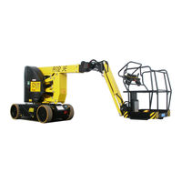
Airo A Series Use And Maintenance Manual (122 pages)
Self-Propelled Work Platforms
Brand:
Airo
| Category:
Construction Equipment
| Size: 7 MB
Table of Contents
Table of Contents
3
1 Introduction
6
Legal Aspects
6
Delivery of the Machine
6
Declaration of Commissioning, First Check, Further Periodical Checks and Transfers of Ownership
6
Declaration of Commissioning and First Check
6
Further Periodical Checks
7
Transfers of Ownership
7
Operator Training and Information
7
Tests Performed before Delivery
7
Intended Use
7
Leaving at Height
8
Description of the Machine
8
Control Panels
9
Drive Power
9
Machine Life, Demolition and Decommissioning
9
Identification
10
Location of Main Components
11
2 Technical Features of Standard Machines
12
Model A12 JE
12
Model A15 JE
15
Model A17 JE
18
Model A12 JED
21
Model A15 JED
24
Vibrations and Noise
27
3 Safety Precautions
28
Personal Protective Equipment (PPE)
28
General Safety Norms
28
Use Instructions
29
General
29
Handling
29
Operating Procedures
30
Wind Speed According to Beaufort Scale
31
Pressure of the Machine on Ground and Load-Bearing Capacity of Ground
32
High-Voltage Power Lines
33
Dangerous Situations And/Or Accidents
33
4 Installation and Preliminary Checks
34
Becoming Acquainted with the Machine
34
Preliminary Operation Checks
34
5 Use Instructions
35
Platform Control Panel
35
Drive and Steering
37
Platform Positioning Movements
38
Pantograph (Lower Boom) Lifting/Lowering
38
Upper Boom Lifting/Lowering
38
Jib Lifting/Lowering
38
Telescopic Boom Extension/Retraction
38
QUICK UP/QUICK down (Optional)
39
Turret Orientation (Rotation)
39
Jib Rotation (Optional)
39
Platform Rotation
39
Platform Levelling
39
Other Functions of the Platform Control Panel
40
Manual Horn
40
Emergency Stop Button
40
Motor Generator Operation Mode Selector
40
Warning Lights
40
Enabled Control Panel Green Warning Light (ZA)
40
Red Warning Light: Flat Battery (ZB)
40
Drive Controller Fault Warning Light / Diesel Motor Generator Fault / Low Fuel Red Warning Light - OPTIONAL (ZC)
41
Danger Red Warning Light (ZD)
41
Overload Red Warning Light (ZE)
41
AIRO SENTINEL" Anti-Trapping System - OPTIONAL
42
SENTINEL Logic Movements
43
Ground Control Panel and Electric Control Unit
44
On-Off Key and Control Panel Selector (A)
45
Emergency Stop Button (B)
45
Diesel Motor Generator Start Button (C) (Models A12 JED - A15 JED)
45
User Interface Display (D)
45
Powered-On Machine Warning Light (E)
46
Battery Recharge Indicator (F)
46
Diesel Motor Generator Warning Lights (G H L M) - OPTIONAL
46
Levers of Movement of the Platform (N O P Q R S T U)
46
Platform Access
47
Machine Start-Up
47
Diesel Motor Generator Start-Up
48
Machine Stop
48
Normal Stop
48
Emergency Stop Button
48
Diesel Motor Generator Stop
49
Emergency Manual Controls
49
Socket for Electric Tool Connection (Optional)
50
Level and Refuelling (Models A12 JED - A15 JED)
51
End of Work
51
6 Handling and Carrying
52
Handling
52
Carrying
53
Emergency Towing of the Machine
54
7 Maintenance
55
Machine Cleaning
55
General Maintenance
56
Various Adjustments
57
Greasing
58
Hydraulic Circuit Oil Level Check and Change
59
Biodegradable Hydraulic Oil (Optional)
60
Emptying
60
Filters
60
Washing
60
Filling
60
Commissioning / Check
60
MIX
61
Micro-Filtration
61
Disposal
61
Topping up
61
Hydraulic Filter Replacement
62
Suction Filter
62
Return Filter
62
Drive Reduction Gear Oil Level Check and Change
63
Checks in the Use of Synthetic Biodegradable Oil in Drive Reduction Gears (Optional)
63
Telescopic Boom Sliding Blocks Clearance Adjustment
64
Circuit Movements Pressure Relief Valve Operation Check
65
Pressure Relief Valve of Proportional Movement Circuit
65
Pressure Relief Valve of ON-OFF Movement Circuit
66
Operation Check of the Turret Inclinometer
67
Adjustment of the Overload Controller (Load Cell)
69
Overload Controller By-Pass - ONLY for EMERGENCY OPERATIONS
70
Operation Check of M1 Microswitches
71
Operation Check of Microswitches MPT1-MPT2 for A12 JE - A12 JED - A15 JE - A15 JED
72
Operation Check of MPT1-MPT2 Microswitches and PS1A-PS1B Proximity Sensors for A17 JE
73
Operation Check of Dead-Man Pedal Safety System
75
Battery
75
General Instructions for Battery
75
Battery Maintenance
76
Accessing the Battery Compartment
76
Closing the Battery Compartment
77
Battery Maintenance
77
Battery Recharge
77
Battery Charger: Fault Report
79
Battery Replacement
79
8 Marks and Certifications
80
9 Plates and Stickers
81
10 Check Register
83
11 Wiring Diagram
101
12 Hydraulic Diagram
110
13 Declaration of Conformity
112
Advertisement
Airo A Series Use And Maintenance Manual (102 pages)
SELF-PROPELLED WORK-PLATFORMS
Brand:
Airo
| Category:
Boom Lifts
| Size: 5 MB
Table of Contents
Table of Contents
4
Introduction
7
Legal Aspects
7
Delivery of the Machine
7
Declaration of Commissioning, First Check, Further Periodical Checks and Transfers of Ownership
7
Declaration of Commissioning and First Check
7
Further Periodical Checks
8
Transfers of Ownership
8
Operator Training and Information
8
Tests Performed before Delivery
8
Intended Use
8
Leaving at Height
9
Description of the Machine
9
Control Panels
10
Power Supply
10
Machine Life, Demolition and Decommissioning
10
Identification
11
Location of Main Components
12
Technical Features of Standard Machines
13
Model A12 JRTD
13
Model A15 JRTD
16
Vibrations and Noise
19
Safety Precautions
20
Personal Protective Equipment (PPE)
20
General Safety Norms
20
Use Instructions
21
General
21
Handling
21
Operating Procedures
22
Wind Speed According to Beaufort Scale
23
Pressure of the Machine on Ground and Load-Bearing Capacity of Ground
24
High-Voltage Power Lines
25
Dangerous Situations And/Or Accidents
25
Installation and Preliminary Checks
26
Becoming Acquainted with the Machine
26
Preliminary Operation Checks
26
Use Instructions
27
Platform Control Panel
27
Drive and Steering
29
Platform Positioning Movements
30
Pantograph (Lower Boom) Lifting/Lowering
30
Upper Boom Lifting/Lowering
30
Jib Lifting/Lowering
30
Telescopic Boom Extension/Retraction
30
QUICK UP/QUICK down (Optional)
31
Turret Orientation (Rotation)
31
Jib Rotation (Optional)
31
Platform Rotation
31
Platform Levelling
31
Other Functions of the Platform Control Panel
32
Manual Horn
32
Emergency Stop
32
Warning Lights
32
Enabled Control Panel Green Warning Light (ZA)
32
Flat Battery Red Warning Light (ZB) - (Only Active on Electric Models)
32
Diesel Engine Fault / Low Fuel Red Warning Light (ZC)
33
Danger Red Warning Light (ZD)
33
Overload Red Warning Light (ZE)
33
Ground Control Panel and Electric Control Unit
34
Ground Control Panel and Electrical Control Unit OPTIONAL for TIER 4 FINAL and STAGE 5 Engines
35
On-Off Key and Control Panel Selector (A)
36
Emergency Stop Button (B)
36
Diesel Heat Engine Start Button (C)
36
User Interface Display (D)
37
MURPHY Display and DPF Regeneration
37
Powered-On Machine Warning Light (E)
40
Diesel Engine Warning Lights (G, H, L, M)
40
Levers of Movement of the Platform (N, O, P, Q, R, S, T, U)
40
Platform Access
41
Machine Start-Up
41
Diesel Engine Start-Up
42
Machine Stop
42
Normal Stop
42
Emergency Stop
42
Diesel Engine Stop
43
Emergency Manual Controls
44
Hydraulic Block of Type a
44
Hydraulic Block of Type B
45
Socket for Electric Tool Connection (Optional)
46
Fuel Level and Re-Fuelling (Models "ED", "D")
47
End of Work
47
Handling and Carrying
48
Handling
48
Transportation
49
Emergency Towing of the Machine
50
Machine Emergency Towing (Standard)
50
Machine Emergency Towing (Optional)
51
Maintenance
52
Machine Cleaning
52
General Maintenance
53
Various Adjustments
54
Greasing
55
Hydraulic Circuit Oil Level Check and Change
56
Biodegradable Hydraulic Oil (Optional)
57
Emptying
57
Filters
57
Washing
57
Filling
57
Commissioning / Check
57
MIX
58
Micro-Filtration
58
Disposal
58
Topping up
58
Hydraulic Filter Replacement
59
Suction Filter
59
Return Filter
59
Discharge Filter
60
Telescopic Boom Sliding Blocks Clearance Adjustment
60
Circuit Movements Pressure Relief Valve Operation Check
61
Pressure Relief Valve of Proportional Movement Circuit
61
Pressure Relief Valve of ON-OFF Movement Circuit
62
Operation Check of the Turret Inclinometer
63
Adjustment of the Overload Controller (Load Cell)
65
Overload Controller By-Pass - ONLY for EMERGENCY OPERATIONS
66
Operation Check of M1 Microswitches
67
Operation Check of Dead-Man Pedal Safety System
68
Starter Battery
69
Battery Maintenance
69
Starter Battery Recharge
69
Battery Replacement
69
Marks and Certifications
70
Plates and Stickers
71
Check Register
73
Electric Diagrams
88
Hydraulic Diagram
97
Declaration of Conformity Ec Facsimile
99
Advertisement
Related Products
Airo A21J
Airo A23 J
Airo A12 JRTD
Airo A15 JRTD
Airo A18 JRTD PLUS
Airo A18 JRTH PLUS
Airo A18 JRTE PLUS
Airo AIRO-KJR120N
Airo AOD24
Airo AYALA 36 INT
Airo Categories
Lifting Systems
Boom Lifts
Air Conditioner
Construction Equipment
Multi-service Platforms
More Airo Manuals
Login
Sign In
OR
Sign in with Facebook
Sign in with Google
Upload manual
Upload from disk
Upload from URL