Table of Contents
Advertisement
Quick Links
PIATTAFORME AEREE SEMOVENTI
SELF-PROPELLED WORK-PLATFORMS
PLATES-FORMES DE TRAVAIL AUTOMOTRICES
SELBSTFAHRENDE HUBARBEITSBÜHNEN
PLATAFORMAS ELEVADORAS AUTOPROPULSADAS
ZELFRIJDENDE HOOGWERKERS
SJÄLVGÅENDE ARBETSPLATTFORMAR
SAMOKRETNE RADNE PLATFORME
"A" SERIES
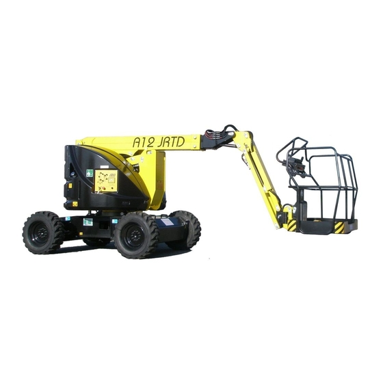
A12 JRTD
A15 JRTD
USE AND MAINTENANCE MANUAL
- ENGLISH - ORIGINAL INSTRUCTIONS
AIRO is a division of TIGIEFFE SRL
Via Villa superiore, 82 - 42045 Luzzara (RE) ITALY-
+39-0522-977365 -
+39-0522-977015
WEB:
www.airo.com
057.20.UEM-EN
2020 - 12
Advertisement
Table of Contents

Related Manuals for Airo A12 JRTD


Summary of Contents for Airo A12 JRTD
- Page 1 SAMOKRETNE RADNE PLATFORME "A" SERIES A12 JRTD A15 JRTD USE AND MAINTENANCE MANUAL - ENGLISH - ORIGINAL INSTRUCTIONS AIRO is a division of TIGIEFFE SRL Via Villa superiore, 82 - 42045 Luzzara (RE) ITALY- +39-0522-977365 - +39-0522-977015 WEB: www.airo.com...
- Page 3 Revision date Description of revision • 2010-01 Manual issue. • Biodegradable oil instructions introduced. 2010-11 • Temperatures and oil list updated. 2010-12 • Instructions for emergency towing with optional pump introduced. • Amended information on “Commissioning and first inspection, subsequent inspections and title transfer report”.
-
Page 4: Table Of Contents
Tigieffe thanks you for purchasing a product of its range, and invites you to read this manual. Here you can find all the necessary information for a correct use of the purchased machine; therefore, you are advised to follow the instructions carefully and to read the manual thoroughly. - Page 5 5.1.3. Other functions of the platform control panel ....................32 5.1.3.1. Manual horn ..............................32 5.1.3.2. Emergency stop .............................. 32 5.1.3.3. Warning lights..............................32 5.1.3.3.1. Enabled control panel green warning light (ZA) ....................32 5.1.3.3.2. Flat battery red warning light (ZB) – (Only active on electric models) ............. 32 5.1.3.3.3.
- Page 6 7.2.5. Telescopic boom sliding blocks clearance adjustment ................... 60 7.2.6. Circuit movements pressure relief valve operation check ................61 7.2.6.1 Pressure relief valve of proportional movement circuit ................... 61 7.2.6.2. Pressure relief valve of ON-OFF movement circuit ..................62 7.2.7. Operation check of the turret inclinometer ......................
-
Page 7: Introduction
Your machine since supplied on request or not available. In order to keep pace with the technical development AIRO-Tigieffe s.r.l. reserves the right to modify the product and/or the use and maintenance manual at any time without updating the units already delivered. -
Page 8: Further Periodical Checks
1.1.2.2. Further periodical checks Yearly checks are compulsory. In Italy it is necessary that the owner of the Aerial Platform must apply for a periodical check by sending a registered letter to the local competent inspection board (ASL/USL or ARPA or other qualified public or private services) at least twenty days before the expiry of the year from the last check. -
Page 9: Leaving At Height
All types of machine use other than those for which it was designed must be approved in writing by the machine manufacturer following a specific request on the part of the user. Do not use the machine for purposes other than those for which it was designed, except after making a request and having obtained written permission in this sense from the manufacturer 1.3.1. -
Page 10: Control Panels
The platform, hinged to the end of the “jib”, can be rotated by 180° totally (90° on the right and 90° on the left) by means of a rotary actuator fitted with over-centre valve. It is fitted with rails and toe boards of prescribed height (the rails height 1100 mm;... -
Page 11: Identification
Identification 1.8. In order to identify the machine, when spare parts and service are required, always mention the information given in the serial number plate. Should this plate (as well as the various stickers applied on the machine) be lost or illegible, it is to be replaced as soon as possible. -
Page 12: Location Of Main Components
Location of main components 1.9. The picture shows the machine and its own components. 1) Control panel 2) Ground controls 3) Electric control unit 4) Hydraulic oil tank 5) Diesel fuel tank 6) Diesel Engine 7) Drive pump 8) Movement pump 9) Hydraulic drive motors 10) Turret rotation hydraulic motor 11-12... -
Page 13: Technical Features Of Standard Machines
TECHNICAL FEATURES OF STANDARD MACHINES THE TECHNICAL FEATURES OF THE PRODUCTS IN THE FOLLOWING PAGES CAN BE MODIFIED WITHOUT PRIOR NOTICE Model A12 JRTD 2.1. A12 JRTD Dimensions: Maximum working height 12.2 40’ Max. platform height 10.2 33' 5" Ground clearance 9.8"... - Page 14 Diesel Power YANMAR “Stage III” Diesel engine type 3TNV-88 3TNV-88 Max. motor power 28.2 37.8 Adjusted Power 33.5 Starter battery 12 / 132 V/Ah 12 / 132 V/Ah Total electrolyte quantity of battery 1.85 Diesel oil tank capacity 18.5 Diesel Power YANMAR “Stage V / Tier 4 final” Diesel engine type 3TNV-88 3TNV-88...
- Page 15 Use and Maintenance Manual – A12 JRTD A15 JRTD Series Page 15...
-
Page 16: Model A15 Jrtd
Model A15 JRTD 2.2. A15 JRTD Dimensions: Maximum working height 15.1 49’ 6” Max. platform height 13.1 42’ 11” Ground clearance 9.8” Max. outreach from turntable centre 28' 10" Turret rotation (not continuous) ° ° Platform rotation ° ° Platform height for safety speed activation <... - Page 17 Diesel Power YANMAR “Stage III” Diesel engine type 3TNV-88 3TNV-88 Motor power 37.5 Starter battery 12 / 132 V/Ah 12 / 132 V/Ah Total electrolyte quantity of battery 1.85 Diesel oil tank capacity 18.5 Diesel Power YANMAR “Stage V / Tier 4 final” Diesel engine type 3TNV-88 3TNV-88...
- Page 18 Use and Maintenance Manual – A12 JRTD A15 JRTD Series Page 18...
-
Page 19: Vibrations And Noise
Vibrations and noise 2.3. Noise tests have been carried out under the most unfavourable conditions to study the effects on the operator. The level of acoustic pressure weighed (A) at work places does not exceed 70dB(A) for each electrical model. For the Diesel engine models, the level of acoustic pressure weighed (A) at work places does not exceed 106dB(A), the level of acoustic pressure at ground control panel does not exceed 85dB(A), the level of acoustic pressure at platform control panel does not exceed 78dB(A). -
Page 20: Safety Precautions
SAFETY PRECAUTIONS Personal protective equipment (PPE) 3.1. Always wear personal protective equipment according to current regulations concerning industrial health and safety (in particular, hard hat and safety shoes are COMPULSORY). It is the operator or safety manager’s responsibility to choose the personal protective equipment (PPE) depending on the activity to be carried out. -
Page 21: Use Instructions
Use instructions 3.3. 3.3.1. General The electric and hydraulic circuits are provided with safety devices, calibrated and sealed by the manufacturer: DO NOT TAMPER WITH AND MODIFY THE CALIBRATION OF ANY COMPONENT OF THE ELECTRIC AND HYDRAULIC SYSTEMS. ▪ The machine must be used only in areas well lit up, checking that the ground is flat and firm. The machine may not be used if the lighting conditions are not sufficient. -
Page 22: Operating Procedures
Pay particular attention to the area above the machine during lifting to avoid any crushing and collisions. ▪ During operation keep your hands in safety position, the driver has to place them as shown in picture A or B ▪ while the transported operator has to keep them as shown in picture C. -
Page 23: Wind Speed According To Beaufort Scale
3.3.4. Wind speed according to Beaufort scale You can use the table below for a simple assessment of the wind speed. We remember that the max. limit for each machine model is indicated in the table TECHNICAL FEATURES OF STANDARD MACHINES. The machines for which the max. -
Page 24: Pressure Of The Machine On Ground And Load-Bearing Capacity Of Ground
3.3.5. Pressure of the machine on ground and load-bearing capacity of ground Before using the machine, the operator must make sure the floor is suitable for withstanding the specific loads and pressures on the ground with a certain safety margin. The following chart provides the parameters in play and two examples of calculation of the average pressure on the ground below the machine and max pressure underneath the wheels or stabilizers (p1 and p2). -
Page 25: High-Voltage Power Lines
The table below shows the load-bearing capacity of the ground split up by ground type. Refer to the data contained in the specific tables of each model (chapter 2, TECHNICAL FEATURES OF STANDARD MACHINES) to obtain the figure relating to the max pressure on the ground caused by the single wheel. Using the machine is forbidden if the max ground pressure per wheel is higher than the bearing capacity of the specific type of ground on which the machine is to be used. -
Page 26: Installation And Preliminary Checks
INSTALLATION AND PRELIMINARY CHECKS The machine is supplied completely assembled, therefore it can perform all functions in full safety as provided for by the manufacturer. No preliminary operation is required. To unload the machine, follow the instructions in chapter “Handling and carrying”. -
Page 27: Use Instructions
USE INSTRUCTIONS Before using the machine read this chapter thoroughly. WARNING! Follow exclusively the instructions given in the next paragraphs and the safety rules described both hereafter and in the previous paragraphs. Read the next paragraphs carefully in order to properly understand the on/off procedures as well as all operations and their correct use. - Page 28 Drive proportional joystick control Proportional lever control pantograph up/down Proportional lever control boom up/down Proportional lever control jib up/down Proportional lever control telescopic boom out/in Proportional lever control QUICK UP/QUICK DOWN (OPTIONAL) Proportional lever control turret rotation Proportional lever control jib rotation (OPTIONAL) Platform rotation switch Platform level switch Diesel engine start button...
-
Page 29: Drive And Steering
5.1.1. Drive and steering Before carrying out any displacement operation, verify that no people are in proximity of the machine and in any case proceed with the utmost caution. IT IS FORBIDDEN to drive the machine when the platform is lifted unless the chassis is flat and steady with no holes and steps. -
Page 30: Platform Positioning Movements
5.1.2. Platform positioning movements To carry out all movements other than drive, use proportional levers B, C, D, E, F, G, H and switches I and L. To achieve the movement, it is necessary to carry out the following operations in sequence: a) Press the dead-man pedal located on the platform;... -
Page 31: Quick Up/Quick Down (Optional)
5.1.2.5. QUICK UP/QUICK DOWN (optional) This lever controls the quick lifting/lowering of the platform, while simultaneously controlling the following manoeuvres: Pantograph lifting/lowering. ▪ ▪ Upper boom lifting/lowering. Jib lifting/lowering. ▪ Telescopic boom extension/retraction. ▪ To carry out the QUICK UP/QUICK DOWN manoeuvre, use the proportional lever F. Set the proportional lever F forward for quick lifting or backward for lowering. -
Page 32: Other Functions Of The Platform Control Panel
5.1.3. Other functions of the platform control panel 5.1.3.1. Manual horn The horn warns that the machine is moving. It is operated by means of button S. 5.1.3.2. Emergency stop By pressing the red emergency STOP R button all control functions are stopped. Normal functions are enabled by rotating the button of 1/4 turn clockwise. -
Page 33: Diesel Engine Fault / Low Fuel Red Warning Light (Zc)
5.1.3.3.3. Diesel engine fault / low fuel red warning light (ZC) This warning light indicates malfunctioning of diesel engine or low fuel. On steady with machine on; platform control panel; Diesel drive power selected. Diesel Engine off ready for start-up. Insufficient motor oil pressure. -
Page 34: Ground Control Panel And Electric Control Unit
Ground control panel and electric control unit 5.2. The ground control station contains some electronic boards necessary to operate the machine and to carry out safety checks. The electric control unit (or electronic control board) is inside the cowling (located on the tank). The ground control panel is located on the rotating turret (see paragraph "Location of main components") and is used to: Turn the machine ON/OFF. -
Page 35: Ground Control Panel And Electrical Control Unit Optional For Tier 4 Final And Stage 5 Engines
ON-OFF key and ground/platform control panel selector Emergency STOP button Diesel heat engine start button User interface display Powered-on machine warning light Oil warning light Alternator warning light Motor head temperature warning light Air filter warning light PANTOGRAPH LIFTING/LOWERING lever BOOM LIFTING/LOWERING lever JIB LIFTING/LOWERING lever TELESCOPIC BOOM OUT/IN lever... -
Page 36: On-Off Key And Control Panel Selector (A)
IT IS FORBIDDEN to use the ground control panel as a workstation when personnel is on the platform. Use the ground controls only to start/stop the machine, to select the control panel, for DPF regeneration (MURPHY display) or in emergency situations to allow the platform to be recovered. Give the key to authorized persons and keep a duplicate in a safe place. -
Page 37: User Interface Display (D)
5.2.5. User interface display (D) The multifunction display for machine/user interface is used to display: The operation parameters of the machine during normal functioning or in the event of a fault. ▪ ▪ The working hours of the Diesel engine (the working hours are displayed in the format HOURS: MINUTES and the final D). - Page 38 CASE 1. If regeneration is requested by the machine, while the machine is being used, the ZC light (Fig. 7) is activated from the platform, together with an audible alarm and a message on the display (see image below). Then carry out the following steps: Set the machine to rest position.
- Page 39 CASE 2. If regeneration is to be forced, the following conditions must be met: Cooling temperature > 60°C (lower right dial). RPM 800 (engine idling speed; large central dial). At least 50 hours after last regeneration. If the conditions are fulfilled, according to Fig.10, press consecutively: Button A.
-
Page 40: Powered-On Machine Warning Light (E)
If the conditions for starting regeneration are not met, the following message appears Fig.12 The regeneration procedure can be locked at any time by pressing the "INHIBIT" button. The user interface display is also used during any interventions by specialized personnel to calibrate/adjust the working parameters of the machine. -
Page 41: Platform Access
Platform access 5.3. The “access position” is the only one from which loading or unloading of persons and materials is allowed. The “access position” to the work platform is the completely lowered configuration. To get on the platform: Get on the platform hanging on to the entry side rails. ▪... -
Page 42: Diesel Engine Start-Up
5.4.1. Diesel engine start-up By turning the starter key on the platform control panel: In “0” position the Diesel engine is off. ▪ ▪ In “3 sec” position the plugs pre-heating takes place (only for engines with plugs). In “Start” position the motor starts. ▪... -
Page 43: Diesel Engine Stop
5.5.3. Diesel engine stop In order to stop the Diesel engine: On the platform control panel: Turn the starter key anticlockwise to position “0”. ▪ Otherwise, press the emergency stop button. ▪ On the ground control panel: Turn the starter key anticlockwise to position “0”. ▪... -
Page 44: Emergency Manual Controls
Emergency manual controls 5.6. This function is to be used only in emergency situations, when no motive power is available. 5.6.1. Hydraulic block of type A Fig. 14-A In case of fault in the electric or hydraulic system, carry out the following emergency procedures: 1) Push and turn the actuator on the solenoid valve EV11B (A). -
Page 45: Hydraulic Block Of Type B
WARNING: The emergency control can be stopped at any moment by releasing the lever or by stopping the pump. Once you have completed the manual emergency operation it is necessary to return everything to the initial conditions and have the lever sealed by an authorized service centre. 5.6.2. -
Page 46: Socket For Electric Tool Connection (Optional)
Correspondence of the solenoid valves and manual operations. Electric valve name Movement Operate the manual operator Pantograph lifting Pull Pantograph lowering Push Telescopic boom extension Pull Telescopic boom retraction Push EV12 Turret anticlockwise rotation Pull EV13 Turret clockwise rotation Push EV14 Upper boom lifting Pull... -
Page 47: Fuel Level And Re-Fuelling (Models "Ed", "D")
Fuel level and re-fuelling (models “ED”, “D”) 5.8. Before using the thermic drive power (diesel engine), check the fuel level in the tank. This operation is to be carried out by visually checking the fuel level via the indicator on the tank visible next to the ground control panel. -
Page 48: Handling And Carrying
HANDLING AND CARRYING Handling 6.1. Before using the machine, make sure that the mechanical lock device of the turret is disabled (see figure aside). To handle the machine in normal operating conditions, follow the instructions given in chapter "USE INSTRUCTIONS" under paragraph "Drive and steering”. When the platform is completely lowered (booms down, telescopic boom completely in and jib at a height between +10°... -
Page 49: Transportation
Transportation 6.2. In order to carry the machine to the various working sites, follow the instructions given below. Considering the large dimensions of some models, before carrying, it is recommended to inquire about the overall dimension limits for road transport in force in your country. Before carrying the machine, turn it off and remove the keys from the control panels. -
Page 50: Emergency Towing Of The Machine
Through a lift truck of a suitable capacity (see machine weight in table “Technical features” at the beginning of this ▪ manual) equipped with forks having at least the same length as the machine width. Insert the forks as indicated by the stickers on the machine. -
Page 51: Machine Emergency Towing (Optional)
6.3.2. Machine emergency towing (optional) In the event of a fault, to carry out the machine emergency towing with the optional device for emergency towing, you must follow the following procedure: 1) Remove the rear protection cover of the chassis by unscrewing no. -
Page 52: Maintenance
The maintenance operations described below refer to a machine with ordinary working use. In case of difficult conditions of use (extreme temperatures, corrosive environments, etc.) or following long machine inactivity, it will be necessary to contact the AIRO assistance service to change the intervention schedule. -
Page 53: General Maintenance
General maintenance 7.2. The table below indicates the main maintenance operations and their frequency. The machine is equipped with a service hour-meter. Operation Frequency Screw tightening (see paragraph "Various adjustments") After the first 10 working hours Oil level check in hydraulic tank After the first 10 working hours Check of the battery state (charge and liquid level) Every day... -
Page 54: Various Adjustments
7.2.1. Various adjustments Check the conditions of the following components and, if necessary, tighten after the first 10 working hours and, afterwards, at least once a year: 1) Wheel screws 2) Drive motor fixing screws 3) Steering cylinder fixing screws 4) Steering hub pin fixing screws 5) Cage fixing screws 6) Hydraulic fittings... -
Page 55: Greasing
7.2.2. Greasing Grease all articulated joints equipped with greaser (or predisposition for greaser) at least every month. At least once a month, using a spatula or a brush, lubricate the telescopic extension. Moreover, always remember to grease the articulated joints: ▪... -
Page 56: Hydraulic Circuit Oil Level Check And Change
7.2.3. Hydraulic circuit oil level check and change After the first 10 working hours and, afterwards, once a month check the oil level in the tank by means of the provided indicator (detail A in the picture aside) and make sure that the level always lies between the max. -
Page 57: Biodegradable Hydraulic Oil (Optional)
7.2.3.1 Biodegradable hydraulic oil (Optional) At the request of the customer, the machines can be supplied with biodegradable hydraulic oil compatible with the environment. Biodegradable hydraulic oil is completely synthetic, without zinc, non-polluting and highly efficient with saturated ester base, combined with special additives. The machines with biodegradable oil use the same component parts as standard machines, but the use of such type of oil is best taken into account from machine construction. -
Page 58: Mix
7.2.3.7 Mix Mixtures with other biodegradable oils are not allowed. The remaining amount of mineral oil must not exceed 5% of total filling quantity as long as the mineral oil is suitable for the same use. 7.2.3.8 Micro-filtration When making the conversion on second-hand machines, always take into account the high dirt dissolution power of biodegradable oil. -
Page 59: Hydraulic Filter Replacement
7.2.4. Hydraulic filter replacement 7.2.4.1. Suction filter All models are equipped with a suction filter installed inside the tank at the base of the suction tube, which has to be replaced at least every two years. To replace the suction filters installed inside the tank (see figure): ▪... -
Page 60: Discharge Filter
7.2.4.3. Discharge filter The discharge filter is represented in the picture to the side. The filtering cartridge should be replaced at least every two years. To replace the filtering cartridge: Stop the machine by pressing the emergency stop ▪ button on the ground control unit. ▪... -
Page 61: Circuit Movements Pressure Relief Valve Operation Check
7.2.6. Circuit movements pressure relief valve operation check 7.2.6.1 Pressure relief valve of proportional movement circuit The pressure relief valve described controls the maximum Type A pressure on the circuit of proportional movements (pantograph, upper boom, telescopic boom, jib, turret rotation, jib rotation). Normally, this valve does not require any adjustment, since it is calibrated at the factory before the machine is delivered. -
Page 62: Pressure Relief Valve Of On-Off Movement Circuit
7.2.6.2. Pressure relief valve of ON-OFF movement circuit The described pressure relief valve controls the maximum Type A pressure of the ON-OFF movement circuit (steering, cage rotation, cage levelling). Normally, this valve does not require any adjustment, since it is calibrated at the factory before the machine is delivered. -
Page 63: Operation Check Of The Turret Inclinometer
7.2.7. Operation check of the turret inclinometer WARNING! Usually the inclinometer does not need to be adjusted unless the electronic control unit is replaced. The equipment necessary for the replacement and adjustment of this component is such that these operations should be carried out by skilled personnel. AS THIS OPERATION IS VERY IMPORTANT IT IS TO BE CARRIED OUT BY SKILLED TECHNICIANS ONLY. - Page 64 SHIMS A12 JRTD - A15 JRTD A [mm] B [mm] WARNING! The dimensions of shims A and B refer to max. allowed inclination as indicated in table “TECHNICAL FEATURES”. To be used during the inclinometer calibration. Use and Maintenance Manual – A12 JRTD A15 JRTD Series Page 64...
-
Page 65: Adjustment Of The Overload Controller (Load Cell)
AS THIS OPERATION IS VERY IMPORTANT IT IS TO BE CARRIED OUT BY SKILLED TECHNICIANS ONLY. The AIRO self-propelled articulated boom aerial platforms are equipped with a sophisticated overload controller. Normally the overload controller does not require any adjustments, since it is calibrated in the factory before the machine is delivered. -
Page 66: Overload Controller By-Pass - Only For Emergency Operations
The system needs calibration: ▪ In case of replacement of one of the items composing the system. When, following an excessive overload or a collision, without the excessive load the danger condition is signalled ▪ anyway. 7.2.9. Overload controller by-pass – ONLY FOR EMERGENCY OPERATIONS In case of fault and impossibility to calibrate the device, a by-pass of the system is possible by means of locking key switch (A) under the control panel. -
Page 67: Operation Check Of M1 Microswitches
7.2.10. Operation check of M1 microswitches The lifting booms are controlled by microswitches: M1A on the pantograph. ▪ M1B on the boom. ▪ ▪ M1C on the Jib. M1E on the telescopic extension. ▪ Once a year check the working conditions of the microswitches M1. -
Page 68: Operation Check Of Dead-Man Pedal Safety System
7.2.11. Operation check of dead-man pedal safety system The platform dead-man pedal is for enabling the operation controls of the machine on the platform control panel. Check operation at least once a year. To check the dead-man PEDAL: ▪ Move the drive joystick forward and backward in sequence, WITHOUT PRESSING THE DEAD-MAN PEDAL. Check that the machine does not perform any movement. -
Page 69: Starter Battery
Starter battery 7.3. The battery is one of the most important elements of the machine. It is recommended to keep it in an efficient condition to increase its useful life, to avoid faults and to reduce the management costs of the machine. On machines with heat engine the starter battery is for: Powering the machine control circuits. -
Page 70: Marks And Certifications
MARKS AND CERTIFICATIONS The models of self-propelled aerial platform described in this manual were subject to the CE type test according to the Directive 2006/42/EC. The certification was issued by: Eurofins Product Testing Italy Srl - 0477 Via Cuorgné, 21 10156 –... -
Page 71: Plates And Stickers
008.10.020 Triangle hot parts sticker 029.10.005 Fuel tank sticker 030.10.008 Sound power level sticker 105 dB 001.10.175 AIRO pre-spaced yellow sticker <530x265> 058.10.001 Pre-spaced sticker A15 JRTD black 057.10.001 Pre-spaced sticker A12 JRTD black 045.10.010 (Optional) electric line plug sticker 001.10.021... - Page 72 Use and Maintenance Manual – A12 JRTD A15 JRTD Series Page 72...
-
Page 73: Check Register
10. CHECK REGISTER The check register is released to the user of the platform in conformance with Attachment 1 of Directive 2006/42/EC. This register is to be considered an integral part of the equipment and must accompany the machine for its entire life until its final disposal. - Page 74 REQUIRED PERIODIC INSPECTIONS BY THE REGULATORY AGENCY Date Observations Signature + Stamp Use and Maintenance Manual – A12 JRTD A15 JRTD Series Page 74...
- Page 75 REQUIRED PERIODIC INSPECTIONS BY THE OWNER STRUCTURAL CHECK DESCRIPTION OF OPERATIONS TO BE PERFORMED Check the integrity of the rails; the harness anchoring points; state of the VISUAL CHECK lifting structure; any access ladders; rust; state of the tyres; oil leaks; locking pins on the structure.
- Page 76 REQUIRED PERIODIC INSPECTIONS BY THE OWNER STRUCTURAL CHECK DESCRIPTION OF OPERATIONS TO BE PERFORMED VARIOUS ADJUSTMENTS See chapter 7.2.1 DATE REMARKS SIGNATURE + STAMP 1st YEAR 2nd YEAR 3rd YEAR 4th YEAR 5th YEAR 6th YEAR 7th YEAR 8th YEAR 9th YEAR 10th YEAR See chapter 7.2.2...
- Page 77 REQUIRED PERIODIC INSPECTIONS BY THE OWNER CHECK DESCRIPTION OF OPERATIONS TO BE PERFORMED See chapter 7.2.3. HYDRAULIC TANK OIL LEVEL Daily operation. It is not necessary to indicate its execution every day, CHECK but at least every year when the other operations are carried out. DATE REMARKS SIGNATURE + STAMP...
- Page 78 REQUIRED PERIODIC INSPECTIONS BY THE OWNER CHECK DESCRIPTION OF OPERATIONS TO BE PERFORMED See chapter 7.3 BATTERY STATE Daily operation. It is not necessary to indicate its execution every day, but at least every year when the other operations are carried out. DATE REMARKS SIGNATURE + STAMP...
- Page 79 REQUIRED PERIODIC INSPECTIONS BY THE OWNER CHECK DESCRIPTION OF OPERATIONS TO BE PERFORMED TOTAL OIL CHANGE IN HYDRAULIC TANK See chapter 7.2.3. (EVERY TWO YEARS) DATE REMARKS SIGNATURE + STAMP 2nd YEAR 4th YEAR 6th YEAR 8th YEAR 10th YEAR HYDRAULIC FILTER REPLACING See chapter 7.2.4.
- Page 80 REQUIRED PERIODIC INSPECTIONS BY THE OWNER SAFETY SYSTEM CHECK DESCRIPTION OF OPERATIONS TO BE PERFORMED OPERATION CHECK OF THE See chapter 7.2.7. TURRET INCLINOMETER DATE REMARKS SIGNATURE + STAMP 1st YEAR 2nd YEAR 3rd YEAR 4th YEAR 5th YEAR 6th YEAR 7th YEAR 8th YEAR 9th YEAR...
- Page 81 REQUIRED PERIODIC INSPECTIONS BY THE OWNER SAFETY SYSTEM CHECK DESCRIPTION OF OPERATIONS TO BE PERFORMED M1 MICROSWITCH OPERATION See chapter 7.2.10 CHECK DATE REMARKS SIGNATURE + STAMP 1st YEAR 2nd YEAR 3rd YEAR 4th YEAR 5th YEAR 6th YEAR 7th YEAR 8th YEAR 9th YEAR 10th YEAR...
- Page 82 REQUIRED PERIODIC INSPECTIONS BY THE OWNER SAFETY SYSTEM CHECK DESCRIPTION OF OPERATIONS TO BE PERFORMED DEAD-MAN SYSTEM CHECK See chapter 7.2.11 DATE REMARKS SIGNATURE + STAMP 1st YEAR 2nd YEAR 3rd YEAR 4th YEAR 5th YEAR 6th YEAR 7th YEAR 8th YEAR 9th YEAR 10th YEAR...
- Page 83 REQUIRED PERIODIC INSPECTIONS BY THE OWNER CHECK OF EMERGENCY DEVICES DESCRIPTION OF OPERATIONS TO BE PERFORMED MANUAL EMERGENCY LOWERING See chapter 5.6 CHECK DATE REMARKS SIGNATURE + STAMP 1st YEAR 2nd YEAR 3rd YEAR 4th YEAR 5th YEAR 6th YEAR 7th YEAR 8th YEAR 9th YEAR...
- Page 84 COMPANY DATE MODEL SERIAL NUMBER DELIVERY DATE AIRO – Tigieffe S.r.l. SUBSEQUENT TRANSFERS OF OWNERSHIP COMPANY DATE We affirm that, as of the date quoted above, the technical, dimensional and functional features of this machine were in conformance with what was originally required and that any changes have been recorded in this Register.
- Page 85 SUBSEQUENT TRANSFERS OF OWNERSHIP COMPANY DATE We affirm that, as of the date quoted above, the technical, dimensional and functional features of this machine were in conformance with what was originally required and that any changes have been recorded in this Register. THE SELLER THE PURCHASER SUBSEQUENT TRANSFERS OF OWNERSHIP...
- Page 86 IMPORTANT BREAKDOWNS DATE DESCRIPTION OF BREAKDOWN SOLUTION SPARE PARTS USED DESCRIPTION CODE QUANTITY SERVICE SAFETY MANAGER DATE DESCRIPTION OF BREAKDOWN SOLUTION SPARE PARTS USED DESCRIPTION CODE QUANTITY SERVICE SAFETY MANAGER Use and Maintenance Manual – A12 JRTD A15 JRTD Series Page 86...
- Page 87 IMPORTANT BREAKDOWNS DATE DESCRIPTION OF BREAKDOWN SOLUTION SPARE PARTS USED DESCRIPTION CODE QUANTITY SERVICE SAFETY MANAGER DATE DESCRIPTION OF BREAKDOWN SOLUTION SPARE PARTS USED DESCRIPTION CODE QUANTITY SERVICE SAFETY MANAGER Use and Maintenance Manual – A12 JRTD A15 JRTD Series Page 87...
-
Page 88: Electric Diagrams
11. ELECTRIC DIAGRAMS 053.08.026 SYMB. DESCRIPTION Pag-Col. 2-26 ROUND AUDIBLE ALARM 6-105 LATFORM AUDIBLE ALARM AIRO S 5-95/97 UMPER FOR ENTINEL BTAV 1-15 ATTERY 6-113 VERLOAD CONTROLLER BY PASS SELECTOR 1-04 LUGS 1-03 LECTRIC ACCELERATOR 1-08 LECTRIC STOP 3-45 ORWARD DRIVE SOLENOID VALVE... - Page 89 5-94 RIVE TOP LIMIT SWITCH 4-64 LOCKWISE TURRET ROTATION TOP LIMIT SWITCH 4-65 NTICLOCKWISE TURRET ROTATION TOP LIMIT SWITCH 1-12 TARTER MPT1 4-65 IGHT POT HOLE LIMIT SWITCH MPT2 4-66 EFT POT HOLE LIMIT SWITCH 1-05 IESEL 1-00 IL PRESSURE SENSOR 1-12 AIN RELAY 1-12...
- Page 90 Use and Maintenance Manual – A12 JRTD A15 JRTD Series Page 90...
- Page 91 Use and Maintenance Manual – A12 JRTD A15 JRTD Series Page 91...
- Page 92 Use and Maintenance Manual – A12 JRTD A15 JRTD Series Page 92...
- Page 93 Use and Maintenance Manual – A12 JRTD A15 JRTD Series Page 93...
- Page 94 Use and Maintenance Manual – A12 JRTD A15 JRTD Series Page 94...
- Page 95 Use and Maintenance Manual – A12 JRTD A15 JRTD Series Page 95...
- Page 96 Use and Maintenance Manual – A12 JRTD A15 JRTD Series Page 96...
-
Page 97: Hydraulic Diagram
12. HYDRAULIC DIAGRAM 057.07.001 DIESEL ENGINE GEAR PUMP (MOVEMENTS) (DRIVE) PISTON PUMP QUICK COUPLING RETURN FILTER SUCTION FILTER EMERGENCY OPERATION HAND PUMP OIL TANK ON-OFF MOVEMENTS HYDRAULIC BLOCK PROPORTIONAL MOVEMENTS HYDRAULIC BLOCK JIB MOVEMENTS HYDRAULIC BLOCK FRONT HYDRAULIC MOTOR REAR HYDRAULIC MOTOR DRIVE HYDRAULIC BLOCK STEERING CYLINDER TELESCOPIC BOOM EXTENSION CYLINDER... - Page 98 Use and Maintenance Manual – A12 JRTD A15 JRTD Series Page 98...
-
Page 99: Declaration Of Conformity Ec Facsimile
13. DECLARATION OF CONFORMITY EC FACSIMILE ORIGINAL EC DECLARATION OF CONFORMITY 2006/42/CE Tigieffe s.r.l. - Via Villa Superiore N.° 82 - Luzzara (Reggio Emilia) - ITALIA Declare under our sole responsibility that the product: Mobile Elevating Work Platform Model Chassis No. - Page 100 ORIGINAL EC DECLARATION OF CONFORMITY 2006/42/CE Tigieffe s.r.l. - Via Villa Superiore N.° 82 - Luzzara (Reggio Emilia) - ITALIA Declare under our sole responsibility that the product: Mobile Elevating Work Platform Model Chassis No. Year A15 JRTD XXXXXXXXXX XXXXXXXXXX To which this declaration refers is in conformity with Directives 2006/42/EC, 2014/30/EC, 2005/88/EC and the model...
- Page 102 TIGIEFFE S.r.l. a socio unico Via Villa Superiore, 82 - 42045 Luzzara (RE) ITALY- +39-0522-977365 - +39-0522-977015 WEB: www.airo.com – e-mail: info@airo.com Use and Maintenance Manual – A12 JRTD A15 JRTD Series Page 102...
Need help?
Do you have a question about the A12 JRTD and is the answer not in the manual?
Questions and answers