Table of Contents
Advertisement
Advertisement
Table of Contents

Subscribe to Our Youtube Channel
Related Manuals for Genius Brain 17


Summary of Contents for Genius Brain 17
- Page 1 BRAIN 17 BRAIN 17...
-
Page 2: Ce Declaration Of Conformity
CE DECLARATION OF CONFORMITY Manufacturer: FAAC S.p.A. Address: Via Calari, 10 - 40069 Zola Predosa BOLOGNA - ITALY Declares that: BRAIN 17 remote Programmer conforms to the essential safety requirements of the following EEC directives 2006/95/EC Low Voltage Directive 2004/108/EC Electromagnetic Compatibility Directive... -
Page 3: Warnings For The Installer
0.03 A is fitted upstream of the system. tions is not permitted. MEANING OF THE SYMBOLS USED Important for the safety of persons and for the Notes on the characteristics and operation of good condition of the automated system. the product. BRAIN 17 732788 - Rev. A_1... -
Page 4: Table Of Contents
7. START-UP ..........................34 7.1 CHECKING THE LEDs ......................34 8. SIGNALLING ERRORS AND ALARMS ................35 8.1 ERRORS ..........................35 8.2 ALARMS ..........................36 9. TROUBLESHOOTING ......................36 10. MANAGING THE CONFIGURATION FILE – J8 USB ............37 11. FUNCTION LOGICS ......................40 BRAIN 17 732788 - Rev. A_1... -
Page 5: Technical Specifications
CONTROL BOARD BRAIN 17 We thank you for having chosen one of our products. GENIUS is certain that from it you will obtain all the performance you require. All our products are the result of years of experience in the field of automated systems. -
Page 6: Preparing For Installation
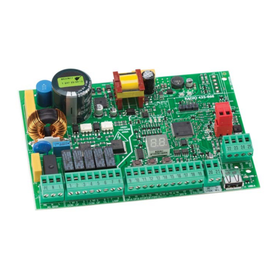
1 2 3 4 5 6 7 8 9 10 11 12 13 14 15 16 17 18 19 20 21 USB-A AC MAIN LAMP OP-A OP-B STOP CL FSW OP TX FSW W.L. LOCK BRAIN 17 732788 - Rev. A_1... - Page 7 W.L. (programmable) and Electric lock (LOCK) output connector DL11 “RADIO1” Signalling LED Motor and power supply safety fuse DL12 “RADIO2” Signalling LED DL13 “ERROR” Error/alarm signalling LED “BUS MON” BUS G-WAY diagnostic signalling DL14 BRAIN 17 732788 - Rev. A_1...
-
Page 8: Electrical Connections
M2 - COM Common contact motor 2 of motor rotation, (see 5.4 TIME LEAR- NING - SETUP) M2 - OP Opening phase motor 2 M2 - CL Closing phase motor 2 LAMP Flashing lamp connection (MAX 60 W) BRAIN 17 732788 - Rev. A_1... -
Page 9: J3 - Low-Voltage Accessories - Inputs/Outputs
FAIL-SAFE safety is not active; otherwise jumper FSW CL and FSW OP and OUT1 (FAIL-SAFE). GND Accessories power supply negative +24 Accessories power supply positive (MAX. load = 500mA) TXFSW FAILSAFE negative Fig. e.g.: Connecting 2 N.O. contacts in parallel. Fig. e.g.: Connecting 2 N.C. contacts in series. BRAIN 17 732788 - Rev. A_1... -
Page 10: J12 - Programmable Outputs - Electric Locks
Fig. Limit switch and TIMECODER connections (maximum configuration: TIMECODER 2 TIMECODER 1 TIMECODER 2 TIMECODER 1 FCA1, FCC1 and TIMECODER1 correspond to LEAF 1; FCA2, FCC2 and TIMECODER2 correspond to LEAF 2. BRAIN 17 732788 - Rev. A_1... -
Page 11: J10 - Bus G-Way Accessories
- suitable for protec- ting the entire movement area from risk of impact. Pulse generators: used as pulse generators for opening the automated system. Closing safety devices Opening safety devices BRAIN 17 732788 - Rev. A_1... - Page 12 Connection of BUS G-WAY photocells For connecting you have to use two cables without polarity (see the specific device instructions). DL1 = Alignment DL2 = BUS G-WAY status/ Power supply DS1 = Programming Dip-switches BUS G-WAY BRAIN 17 732788 - Rev. A_1...
- Page 13 Cable Inversion Note: by inverting the encoder wires, this will switch around the encoder associated with Encoder Encoder leaf 1 and the encoder associated with leaf 2 Leaf 1 Leaf 2 and vice versa. BRAIN 17 732788 - Rev. A_1...
-
Page 14: J5 - Rqfz Module Rapid Connector
FLASHING. 4.7 J5 - RQFZ MODULE RAPID CONNECTOR Plug-in rapid connector dedicated to RQFZ2-chan- nel decoding module. ALWAYS cut off power to the board BE- FORE inserting/removing the module. RADIO1 RADIO2 DL11 DL12 ERROR BRAIN 17 732788 - Rev. A_1... -
Page 15: Traditional Photocells
CL FSW OP TX FSW W.L. LOCK LOCK 9 10 11 12 13 14 15 16 17 18 19 20 21 9 10 11 12 13 14 15 16 17 18 19 20 21 BRAIN 17 732788 - Rev. A_1... - Page 16 OP-A OP-A OP-B OP-B STOP STOP CL FSW OP TX FSW W.L. LOCK LOCK 9 10 11 12 13 14 15 16 17 18 19 20 21 RX CL TX CL Other safety devices BRAIN 17 732788 - Rev. A_1...
- Page 17 9 10 11 12 13 14 15 16 17 18 19 20 21 9 10 11 12 13 14 15 16 17 18 19 20 21 RX CL TX CL Other RX OP TX OP safety devices TX OP/CL RX OP/CL BRAIN 17 732788 - Rev. A_1...
-
Page 18: Programming
DISPLAYED TO VISUALIZE THE FUNCTION DESIRED ONE THE PROGRAMMING AUTOMATED SYSTEM APPEARS +/R1 -/R2 STATUS OTHERWISE SELECT TO EXIT +/R1 THE PROGRAMMING WITHOUT SAVING +/R1 THE FUNCTION IS DISPLAYED UNTIL YOU HOLD BRAIN 17 732788 - Rev. A_1... -
Page 19: Basic Programming Functions
OPEN B inputs will automatically be changed to CLOSE. , if you choose a logic that does not require the use of CLOSE inputs, these inputs will change to OPEN B. For a description of how the logics operate, see the related paragraph. BRAIN 17 732788 - Rev. A_1... - Page 20 If a SETUP is performed with two motors and later only one is used, the board will not signal an error. Only the motor connected to input M1 will move. BRAIN 17 732788 - Rev. A_1...
- Page 21 = the limit switch determines the start of deceleration After having changed the value of this function, SETUP is required: the card will signal error (configuration error) until the SETUP is performed again or until the previous value is restored BRAIN 17 732788 - Rev. A_1...
- Page 22 (separated by a decimal point) and time is adjusted in 10-second steps up to the maximum value of minutes. e.g.: if the display shows , the time is 1 min and 20 sec BUS G-WAY DEVICES ENTRY: See the related paragraph. BRAIN 17 732788 - Rev. A_1...
- Page 23 WARNING If power is lost to the board prior to confirmation (step 2.), all changes made will be lost. You can EXIT programming at any time: press and hold F and then also - to switch directly to -/R2 BRAIN 17 732788 - Rev. A_1...
-
Page 24: Advanced Programming Functions
LEAF 2 DECELERATION (visualised only with the function You can adjust the deceleration space as a percentage of the total travel of leaf 2. Adjustable from %, in 1% steps. = no deceleration = minimum deceleration space = maximum deceleration space BRAIN 17 732788 - Rev. A_1... - Page 25 You can set the output W.L. (open collector N.O.) in one of the following functions: = INDICATOR LIGHT (OFF = closed, ON = during opening and open/ pause, FLASHING = during closing) = COURTESY LIGHT (fixed time 90 seconds) BRAIN 17 732788 - Rev. A_1...
- Page 26 WARNING If power is lost to the board prior to confirmation (step 2.), all changes made will be lost. You can EXIT programming at any time: press and hold F and then also - to switch directly to -/R2 BRAIN 17 732788 - Rev. A_1...
-
Page 27: Bus G-Way Device Installation
OPEN photocell: ON = entered and engaged Closing photocells: ON = entered and engaged Fig. Visualising the BUS G-WAY status in the function : each segment of the display shows one type of device. BRAIN 17 732788 - Rev. A_1... - Page 28 - That there are no more than one device in the system with the same Rapid blinking (blink every 0.5 sec) address. - Calling error (number > or < the connected BUS devices). - FAIL SAFE error on the BUS device. Board in Sleep mode (if used). BRAIN 17 732788 - Rev. A_1...
-
Page 29: Time Learning - Setup
(the limit switch determines the stopping of motion) the OPEN A pulse for stopping motion is ignored. (the limit switch determines the start of deceleration) send an OPEN A pulse only after involving the opening limit switch. BRAIN 17 732788 - Rev. A_1... -
Page 30: Testing The Automated System
Once installation and programming is completed, ensure that the system is operating correctly. Be especially careful that the safety devices operate correctly and ensure that the system complies with all current safety regulations. Close the cover in the provided seat with gasket. BRAIN 17 732788 - Rev. A_1... -
Page 31: Memorising The Radio Code
Ensure that there are no obstacles (by people or things) during the automated system movement. 5” 5” 2 x 2” > 30 cm 2” P1 + P2 > 5” +/R1 +/R1 1” 1” DL11 20” 20” RADIO 1 BRAIN 17 732788 - Rev. A_1... -
Page 32: Memorising Rc Radio Controls (Only 433 Mhz)
When the 20 sec have elapsed, the LED will turn off, indicating that the procedure has been completed. 4. To add other radio controls, repeat the procedure from point 1. > 30 cm > 5” +/R1 +/R1 1” DL11 20” 20” 20” 20” RADIO 1 BRAIN 17 732788 - Rev. A_1... -
Page 33: Remote Memorisation Of Rc Radio Controls
Once rapid flashing has stopped, LEDs DL11 and DL12 will go on steady, confirming the cancellation of all the radio codes (OPEN A and OPEN B/CLOSE) from the board memory. 2. Release -/R2 . The LEDs will go off, indicating correct cancellation. -/R2 BRAIN 17 732788 - Rev. A_1... -
Page 34: Start-Up
DL2 FCA2 OPEN limit switch clear engaged movement of leaf 2. When the leaf is stationary, they can both CLOSE limit switch DL1 FCC2 CLOSE limit switch clear be either on or off engaged BRAIN 17 732788 - Rev. A_1... -
Page 35: Signalling Errors And Alarms
Motor 1 encoder fault Check the connections or replace motor 1 encoder Motor 2 encoder fault Check the connections or replace motor 2 encoder Incorrect memory data Repeat BUS G-WAY device entry and/or re-program the board BRAIN 17 732788 - Rev. A_1... -
Page 36: Alarms
Check that the photocell wiring and alignment is correct • Check that there is no OPEN signal active The gate will not close • Check which function logic has been chosen (automatic or semi-automatic) BRAIN 17 732788 - Rev. A_1... -
Page 37: Managing The Configuration File - J8 Usb
Once updating is completed, will be displayed if it has been done correctly, otherwise the writing will appear again. The upgrade is carried out correctly only if the USB memory contains a valid file named exactly BRN17SW.bin BRAIN 17 732788 - Rev. A_1... - Page 38 Once updating is completed will be displayed if it has been done correctly, otherwise the writing will appear again. The upgrade is carried out correctly only if the USB memory contains a valid file named exactly BRN17.rad BRAIN 17 732788 - Rev. A_1...
- Page 39 Press + and - to select the desired parameter and, by pressing F, the board will proceed to save the file and display when done correctly, or in case of errors during saving. BRAIN 17 732788 - Rev. A_1...
-
Page 40: Function Logics
Logic with two separate An OPEN-A pulse During motion, the (OPEN-B commands: a held during closing opens, photocells reverse inputs become OPEN-A pulse opens; a CLOSE pulse during CLOSE) a held CLOSE pulse opening closes closes BRAIN 17 732788 - Rev. A_1... - Page 41 OPPOSITE DIRECTION CLOSES OPEN CLOSE OPEN CLOSE OPEN STOPS ALWAYS CLOSES AFTER STOP DISABLED DISABLED DISABLED SAVES CLOSE if the cycle began with OPEN-B, opens totally operation can be modified by programming BRAIN 17 732788 - Rev. A_1...
- Page 42 NO EFFECT NO EFFECT NO EFFECT OPEN STOPPED CLOSES OPEN CLOSE OPEN CLOSE CLOSE DISABLED DISABLED DISABLED DISABLED if the cycle began with OPEN-B, opens totally operation can be modified by programming BRAIN 17 732788 - Rev. A_1...
- Page 43 NO EFFECT NO EFFECT NO EFFECT OPEN STOPPED OPENS CLOSES OPEN CLOSE OPEN CLOSE CLOSE DISABLED DISABLED DISABLED DISABLED if the cycle began with OPEN-B, opens totally operation can be modified by programming BRAIN 17 732788 - Rev. A_1...
- Page 44 NO EFFECT NO EFFECT NO EFFECT OPEN STOPPED OPENS CLOSES OPEN CLOSE OPEN CLOSE CLOSE DISABLED DISABLED DISABLED DISABLED if the cycle began with OPEN-B, opens totally operation can be modified by programming BRAIN 17 732788 - Rev. A_1...
- Page 45 Sede legale / Registered offi ce: FAAC SpA - Via Calari, 10 40069 Zola Predosa (BO) - Italy Tel. + 39 051 61724 - Fax. +39 051 758518 Supporto tecnico Italia : 051 6172505 www.geniusg.com 732788 - Rev. A_1...
Need help?
Do you have a question about the Brain 17 and is the answer not in the manual?
Questions and answers