Advertisement
CONSTANT
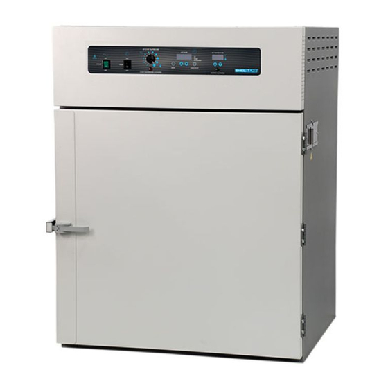
TEMPERATURE OVEN
MICROPROCESSOR
CONTROLLED
FLOOR MODELS:
FX14-2 & FX28-2
02/13
4861581-2
INSTALLATION AND OPERATIONAL MANUAL
Sheldon Manufacturing Inc. P.O. Box 627 Cornelius, Oregon 97113
EMAIL:
tech@Shellab.com
INTERNET:
http://www.Shellab.com/~Shellab
1-800-322-4897
(503) 640-3000
FAX (503) 640-1366
Advertisement
Table of Contents

Related Manuals for Shel lab FX14-2


Summary of Contents for Shel lab FX14-2
- Page 1 CONSTANT TEMPERATURE OVEN MICROPROCESSOR CONTROLLED FLOOR MODELS: FX14-2 & FX28-2 02/13 4861581-2 INSTALLATION AND OPERATIONAL MANUAL Sheldon Manufacturing Inc. P.O. Box 627 Cornelius, Oregon 97113 EMAIL: tech@Shellab.com INTERNET: http://www.Shellab.com/~Shellab 1-800-322-4897 (503) 640-3000 FAX (503) 640-1366...
-
Page 2: Table Of Contents
TABLE OF CONTENTS SECTION 1.0 RECEIVING AND INSPECTION SECTION 2.0 GRAPHIC SYMBOLS SECTION 3.0 INSTALLATION SECTION 4.0 PRECAUTIONS SECTION 5.0 CONTROL PANEL OVERVIEW SECTION 6.0 OPERATION SECTION 7.0 MAINTENANCE SECTION 8.0 TROUBLESHOOTING SECTION 9.0 PARTS LIST UNIT SPECIFICATIONS SCHEMATICS This unit is a special purpose oven for professional, industrial or educational use where the preparation or testing of materials is done at approximately atmospheric pressure and no flammable volatile or combustible materials are being heated or placed near or on top of unit. -
Page 3: Receiving And Inspection
Accessories: Verify that all of the equipment indicated on the packing slip is included with the unit. Carefully check all packaging before discarding. The FX14-2 is equipped with 3 shelves, 12 shelf clips and 4 leveling feet. The FX28- 2 is equipped with 6 shelves, 24 shelf clips and 4 leveling feet. -
Page 4: Graphic Symbols
Section GRAPHIC SYMBOLS Your oven is provided with a display of graphic symbols which should help in identifying the use and function of the available user adjustable components. This symbol indicates that you should consult your manual for further description or discussion of a control or user item. -
Page 5: Installation
Installation of the FX28-2 requires hard wiring and should be performed by a qualified electrical technician. The next higher circuit breaker value above the data plate amperage may be used provided the requirements in article 422 of the National Electric Code are met (USA). The FX14-2 can be installed by the end user without a technician. -
Page 6: Precautions
Section PRECAUTIONS The bottom surface of the chamber should not be used as a work surface. These units have been designed with dampered vents from the chamber. In order to work effectively and safely, some precautions will need to be taken by the operator. -
Page 7: Control Panel Overview
Section CONTROL PANEL OVERVIEW Power Switch: The main power switch on the control panel (green lighted I/O) controls all power to the unit and must be in the I/ON position before any systems are operational. The switch will be lighted when in the I/ON position. Timer Switch: The black I/O switch marked TIMER is located to the right of the power switch. -
Page 8: Operation
Section OPERATION Connection to Power Supply: Assure that the electrical power supply is properly configured and rated for the oven. The FX28-2 must be hard wired as stated in Section 3.0, Installation. Push the POWER switch to the ON position. The digital temperature display will indicate a temperature value. - Page 9 Ten Minute Function: After the correct value for hours is set, push the RESET pad again. The blinking decimal will now move one digit to the right between digits 3 and 4. Pushing the UP or DOWN arrow pads will increase or decrease the ten minute function allowing values between 0 to 5 to be set (digit 3).
-
Page 10: Maintenance
Section MAINTENANCE Cleaning: Clean the oven interior and remove and clean shelves on a regular basis. Use a disinfectant that is suitable for your application. DO NOT USE chlorine-based bleaches or abrasives, as this will damage the stainless steel interior. DO NOT USE spray cleaners that might leak through openings and cracks and get on electrical parts or that may contain solvents that will harm the coatings. -
Page 11: Troubleshooting
Section TROUBLESHOOTING TEMPERATURE Temperature too high. 1/ Controller set too high-see section 6.3 2/ Controller failed on – call Customer Service. 3/ Wiring error – call Customer Service. Display reads "HI" or "400"+. Probe is unplugged, is broken or wire to sensor is broken – trace wire from display to probe;... - Page 12 3/ Is ambient room temperature radically changing – either door opening or room airflow from heaters or air conditioning ? – stabilize ambient conditions. 4/ This may happen if exhaust stack is 100% open or if power exhaust is cycling – adjust stack to at least ¼ closed. 5/ Sensor miss-located, damaged or wires may be damaged - check mounts for control and OTP sensors, then trace wires or tubing between sensors and controls.
- Page 13 2/ Confirm that unit has not been damaged and body is not out of square. 3/ Check physical condition of gasket for tears or punctures. OTHER Controller on at all times - "locked-up" 1/ Adjust set point to room temperature. If the unit is still heating, replace the solid state relay.
-
Page 14: Parts List
EMI Filter FX28-2 2800504 Fuse, 10amp 5 x 20mm 3300516 Green I/O Switch, Power 7850570 Knob, OTP 4450506 Pilot Light, Heating 4650554 Pilot Light, OTP 4650553 OTP Thermostat 1750648 Shelf Clip 1250512 Shelf FX14-2 & FX28-2 5130581 Temp/Time Control 1750613... -
Page 15: Unit Specifications
These units are 240 volt. Please refer to the unit data plate for its individual specifications. Dimensions WxDxH Weight Capacity Unit Exterior Interior Shipping Cubic Ft FX14-2 37X34X47 30.75x24.75x47 490 lbs. 280 lbs. FX28-2 37.5x24.75x78.25 30.75x24.75x62.5 550 lbs. 390 lbs. Heat-up Temp. - Page 16 WIRE DIAGRAM FX14-2 9851289 FUSED INLET 4200505 2800502 FILTER BLACK HT RED HT GREEN LIGHTED SWITCH 7850570 BLUE BLACK BLOWER MOTOR 4880548 WHITE RED HT TEMP BLACK HT 37.0 TEMOERATURE TIMER SWITCH NEUTRAL 7850579 CONTROL WITH TIMER TIMER 1750613 GROUND LOAD ...
- Page 17 WIRE DIAGRAM FX28-2 9851291 2800504 FILTER BLACK 10G BLACK 10G BLACK HT RED HT ½ R1 RELAY ½ R1 RELAY 7030525 7030525 BLACK HT RED HT R1 COIL BLUE BLACK BLOWER MOTOR 4880548 WHITE RED HT TEMP BLACK HT 37.0 NEUTRAL TIMER TEMOERATURE...
- Page 18 SHELDON MANUFACTURING, INC. LIMITED WARRANTY (Parts only, exclusive of labor) Sheldon Manufacturing, Inc., (“Manufacturer”) warrants for the original user of this product that all parts, not including finished goods products, it manufactures or resells will be free from defects in material and workmanship for a period of one year from the date of delivery of this product to the original user (the “Warranty Period”).
Need help?
Do you have a question about the FX14-2 and is the answer not in the manual?
Questions and answers