Advertisement
Quick Links
Sheldon Manufacturing Inc. P.O. Box 627 Cornelius, Oregon 97113
EMAIL:
tech@Shellab.com
1-800-322-4897
I
NSTALLATION
INTERNET:
http://www.Shellab.com/~Shellab
(503) 640-3000
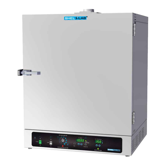
MICROPROCESSOR
CONTROLLED OVEN
SGO5 SGO5-2
P
REVIOUSLY DESIGNATED
CE5G CE5G-2
Revised 12/2013
A
O
ND
PERATION
FAX (503) 640-1366
4861568
M
ANUAL
Advertisement

Subscribe to Our Youtube Channel
Related Manuals for Shel lab SGO5-2


Summary of Contents for Shel lab SGO5-2
- Page 1 MICROPROCESSOR CONTROLLED OVEN SGO5 SGO5-2 REVIOUSLY DESIGNATED CE5G CE5G-2 Revised 12/2013 4861568 NSTALLATION PERATION ANUAL Sheldon Manufacturing Inc. P.O. Box 627 Cornelius, Oregon 97113 EMAIL: tech@Shellab.com INTERNET: http://www.Shellab.com/~Shellab 1-800-322-4897 (503) 640-3000 FAX (503) 640-1366...
- Page 2 TABLE OF CONTENTS SECTION 1.0 RECEIVING AND INSPECTION SECTION 2.0 GRAPHIC SYMBOLS SECTION 3.0 INSTALLATION SECTION 4.0 PRECAUTIONS SECTION 5.0 CONTROL PANEL OVERVIEW SECTION 6.0 OPERATION SECTION 7.0 MAINTENANCE SECTION 8.0 TROUBLESHOOTING SECTION 9.0 PARTS LIST, UNIT SPECIFICATIONS, SCHEMATICS These units are TUV CUE listed as forced air ovens for professional, industrial, or educational use where the preparation or testing of materials is done at approximately atmospheric pressure and no flammable, volatile, or combustible materials are being heated.
- Page 3 Section RECEIVING AND INSPECTION Your satisfaction and safety require a complete understanding of this unit. Read the instructions thoroughly and be sure that all users are given adequate training before attempting to use this unit. Note: This equipment must be used only for its intended purpose;...
- Page 4 Section GRAPHIC SYMBOLS Your oven has been provided with a display of graphic symbols which should help in identifying the use and function of the available user adjustable components. This symbol indicates that you should consult your manual for further description or discussion of a control or user item.
- Page 5 Section INSTALLATION Local city, county or other ordinances may govern the use of this equipment. If you have any questions about local requirements, please contact the appropriate local agency. Installation may be performed by the end user. Under normal circumstance this unit is intended for use indoors, at room temperatures between 5 and 40 C, at no greater than 80% Relative Humidity ( at 25C ) and with a supply voltage that does not vary by more than 10%.
- Page 6 Section PRECAUTIONS The bottom surface of the chamber should not be used as a work surface. This unit has been designed with a dampered vent from the chamber. In order to work effectively and safely, some precautions will need to be taken by the operator.
- Page 7 Section CONTROL PANEL OVERVIEW Power Switch: The main power switch on the control panel (green lighted I/O) controls all power to the oven. It must be in the I/On position before any systems are operational. The green pilot light in the switch will be lighted when the switch is in the ON position. Timer Switch: The black I/O power switch marked TIMER is located to the right of the main power switch.
- Page 8 Section OPERATION Connection to Power Supply: Assure that the electrical power supply is properly configured and rated for the oven and plug the unit cord into the receptacle. Push the main power switch to the On position. The digital temperature display will indicate a temperature value.
- Page 9 values between 0 and 5 to be set (digit 3). One Minute Function: After the correct ten minutes value is set, push the RESET pad again. The blinking decimal point will move one digit to the right beyond digit 4 and be located at the extreme bottom right of the display.
- Page 10 Section MAINTENANCE Note: Disconnect the power cord from the power source before performing any service or maintenance on this unit. Cleaning: Cleaning and decontamination are recommended on a regular basis. To prepare the unit for cleaning, remove all interior parts if assembled, such as shelves and shelf clips.
- Page 11 Section TROUBLESHOOTING TEMPERATURE Temperature too high. 1/ Controller set too high-see section 6.3 2/ Controller failed on – call Customer Service. 3/ Wiring error – call Customer Service. Display reads "HI" or "400"+. Probe is unplugged, is broken or wire to sensor is broken – trace wire from display to probe;...
- Page 12 1/ Check amperage – amperage should be virtually at maximum rated (data plate) amperage. 2/ do all controller functions work? 3/ Is the Safety Thermostat set high enough? – for diagnostics, should be fully clockwise with the OTP light never on. 4/ Has the fuse/circuit breaker blown? 5/ Has timer turned unit off? Indicated chamber temperature...
- Page 13 1) Make sure that the fan or blower wheel is not contacting its housing. Adjust the motor mounting bracket position to re-center the fan or blower wheel, if necessary. 2) Check the fan or blower wheel for damage or out of balance condition.
- Page 14 Section PARTS LIST 115v Description 220V EMI Filter 2800503 2800502 2700512 Adjustable Feet 2700512 4450506 Control Knob 4450506 1800510 Cord Set 1800500 3800605 Door Latch 3800605 Fuse Holder 3300501 Fuse, 10 Amp 250V 3300516 3300513 Fuse, 16 Amp 7850570 I/O (On/Off) Power Switch 7850570 1750615 Overtemperature Safety Thermostat...
- Page 15 UNIT SPECIFICATIONS Weight Shipping All Models 200 lbs. 93 lbs. Dimensions Exterior WxDxH (in.) Interior WxDxH (in.) All Models 30.00 x 25.563 x 38.0 21.00 x 19.50 x 21.00 Capacity Cubic Feet All Models Temperature Range Uniformity Recovery All Models 10...
- Page 16 WIRING DIAGRAM Models...
Need help?
Do you have a question about the SGO5-2 and is the answer not in the manual?
Questions and answers