Table of Contents
Advertisement
U.S. Patent Nos. D730,614; D733,389; D733,390; D734,589; 9,440,830 B2 and 10,214,402
NOTE:This vehicle is for indoor and level surface use only.
NOTE:For the most current parts information and service updates,
please refer to the Big Joe Support site at
Big Lift LLC
www.bigjoeforklifts.com
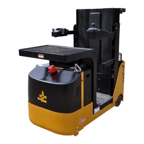
J1 SERIES
(J1-86 / J1-126 / J1-162)
TASK SUPPORT
VEHICLE
Maintenance
Repair Parts Manual
www.bigjoesupport.com
MANUAL NO. BL-J1-0315 - 11-19-2019
Advertisement
Table of Contents
Troubleshooting

Related Manuals for Big Joe Joey J1 Series

Summary of Contents for Big Joe Joey J1 Series
- Page 1 Repair Parts Manual NOTE:This vehicle is for indoor and level surface use only. NOTE:For the most current parts information and service updates, please refer to the Big Joe Support site at www.bigjoesupport.com Big Lift LLC MANUAL NO. BL-J1-0315 - 11-19-2019...
- Page 2 WARNING Do not operate this vehicle unless you have been Before elevating platform be sure guardrail access authorized and trained to do so, and have read all gates are in place and lowered. Keep feet on platform warnings and instructions in Operator’s Manual and on floor at all times while using vehicle, never climb onto this vehicle.
- Page 3 TABLE OF CONTENTS Section Page Section Page LIFT CHAIN LENGTH ADJUSTMENT ..7-1 1 DESCRIPTION ............1-1 LIFT CHAIN WEAR INSPECTION ....7-2 INTRODUCTION ..........1-1 LIFT CHAIN REPLACEMENT...... 7-2 GENERAL DESCRIPTION ......1-1 7-4.1 Telescopic..........7-2 DATA PLATE AND WARNING DECAL ..1-2 7-4.2 Three Stage Mast ........
- Page 4 BL-J1-0315 - 11-19-2019...
- Page 5 SECTION 1 DESCRIPTION 1-1. INTRODUCTION. 1-2. GENERAL DESCRIPTION. This publication describes the 24 volt J1 task support The self-propelled J1 task support vehicle lifts and vehicle by Big Lift LLC. Included are planned mainte- transports up to 1,000 pounds capacity including load nance instructions, lubrication procedures, corrective and operator.
- Page 6 The AC motor propels the vehicle in forward or If the data plate or warning decals are lost or damaged reverse direction. The vehicle can be driven with the they MUST be replaced immediately. Have your platform raised or lowered; however the speed is supervisor or the designated authority contact Big Lift restricted above 24”.
- Page 7 page 1-3 BL-J1-0315 - 11-19-2019...
- Page 8 NOTES BL-J1-0315 - 11-19-2019...
- Page 9 SECTION 2 PLANNED MAINTENANCE 2-1. GENERAL. 2-4. ANNUAL INSPECTIONS. Planned maintenance consists of periodic visual and The owner and user are required by ANSI A92.6 to operational checks, inspection, lubrication, and sched- ensure annual inspections of the J1 Task Support uled maintenance designed to catch an issue in the Vehicle occur and are performed no later than 13 early hours or discover malfunctions and defective...
- Page 10 2-5.2. Safety Rules Charge the battery only in areas designated for that use. • Wear protective clothing, such as rubber apron, Battery terminals should be checked and cleaned gloves, boots and goggles when performing any of corrosion regularly. Good battery terminal con- maintenance on batteries.
- Page 11 OFF. Dispose in accordance with national environmental protection regulations or disposal laws. The manufac- Apply the emergency parking brake. turer’s disposal instructions must be followed * Please refer to the Big Joe Support site at www.bigjoesupport.com BL-J1-0315 - 11-19-2019...
- Page 12 R6115 2-8. LUBRICATION. Refer to Table 2-2 for the recommended types of Table 2-2 Recommended Lubricants grease and oil. Table 2-3 in conjunction with (See Table 2-3 for Application) Figure 2-3 identifies the items requiring lubrication. No. 1 Grease—Polylub GA352P 2-9.
- Page 13 R6988 Figure 2-3 Lubrication Diagram Table 2-3 Lubrication Chart FIG 3-2 LOCATION METHOD OF TYPE APPLICATION INDEX APPLICATION (Table 2-3) LUBRICANT Mast Spray No. 1 Full length of channel where rollers operate. Hydraulic Reservoir No. 2 With platform fully lowered, fill res- ervoir with hydraulic oil to level on dip stick.
- Page 14 Big Lift LLC. J1 - Task Support Vehicle (TSV) www.bigjoesupport.com 1060 N. Garfield St. Annual Inspection Report Lombard, IL 60148 Page 2-6 DEALER INFORMATION OWNER / END USER INFORMATION COMPANY: COMPANY: ADDRESS: ADDRESS: CITY/STATE/ZIP: CITY/STATE/ZIP: VEHICLE INFORMATION: MODEL: SERIAL: MAST SIZE: HOUR METER: BATTERY SPEC.: OPTIONS:...
- Page 15 Big Lift LLC. J1 - Task Support Vehicle (TSV) www.bigjoesupport.com 1060 N. Garfield St. Annual Inspection Report Lombard, IL 60148 VEHICLE INFORMATION: MODEL: SERIAL: MAST SIZE: HOUR METER: DEALER: OWNER / END USER: HYDRAULIC SYSTEM Lift cylinder is free of damage, no evidence of leaks and that all hardware is secure and undamaged. All hydraulic hoses, fittings and components are properly secured and that there is no evidence of leaks.
- Page 16 NOTES BL-J1-0315 - 11-19-2019...
- Page 17 SECTION 3 TROUBLESHOOTING 3-1. GENERAL Operate: Vehicle Does Not Operate Forward or Reverse: Trouble With Braking: Trouble With Lifting Or Table 3-1 as a guide to determine possible Lowering, and Miscellaneous malfunctions. causes of trouble. The table is divided into five main categories: Vehicle and Hydraulic System Will Not Table 3-1 Troubleshooting Chart MALFUNCTION...
- Page 18 Table 3-1 Troubleshooting Chart - Continued MALFUNCTION PROBABLE CAUSE CORRECTIVE ACTION TROUBLE WITH LIFTING OR LOWERING Oil sprays or flows from the top of Defective packing in lift cylinder Repair lift cylinder. the lift cylinder. Squealing sounds when lifting a. Oil level too low. Identify oil leak and fill reservoir.
- Page 19 Table 3-1 Troubleshooting Chart - Continued MALFUNCTION PROBABLE CAUSE CORRECTIVE ACTION TROUBLE WITH LIFTING OR LOWERING - Continued Forks drifts down under load when Leak in hydraulic system, lift cylin- Check for leaking fitting in hydrau- in a raised position. der or lowering valve.
- Page 20 3-2. CONTROLLER TROUBLESHOOTING 3-2.2.2. Logbook Access To view the alarm logbook proceed as follows: 3-2.1. Zapi Handset Connect the Zapi Handset, refer to paragraph A Zapi Handset is available that is designed specifi- 2.1. cally for use with the Zapi controller. It serves multiple functions of reading diagnostic data, testing truck Press the ENTER button (3, Figure...
- Page 21 3-2.4. Factory Settings Press the ROLL down button (2) or the ROLL up button (1) to find the parameter to be checked. Parameter setting are not to be changed from fac- Press the SET up button (5) or the SET down but- tory settings without explicit written permission ton (6) until the factory setting is reached.
- Page 22 Table 3-3 Troubleshooting Chart (Traction/Lift Controller) ERROR ERROR TEXT POSSIBLE CAUSE FAULT CLEARANCE WRONG CONFIG This alarm occurs the first time a control- The AC TYPE 0 setting must be factory ler is switched on when the non volatile adjusted and so the alarm should eeprom memory is not initialized yet.
- Page 23 Table 3-3 Troubleshooting Chart (Traction/Lift Controller) - Continued ERROR ERROR TEXT POSSIBLE CAUSE FAULT CLEARANCE LOGIC FAILURE #1 This alarm signals that an overvoltage/ Normally the overvoltage occurs due to undervoltage protection operation has the regenerative braking energy occurred. increasing the battery voltage; the under voltage of the logic supply, can be due to a depletion in the key volt- age.
- Page 24 Table 3-3 Troubleshooting Chart (Traction/Lift Controller) - Continued ERROR ERROR TEXT POSSIBLE CAUSE FAULT CLEARANCE I=0 EVER This test is carried out when the motor is If everything is OK for the motor, the running, and it verifies that the current problem could be in the related circuit.
- Page 25 Table 3-3 Troubleshooting Chart (Traction/Lift Controller) - Continued ERROR ERROR TEXT POSSIBLE CAUSE FAULT CLEARANCE CAPACITOR CHARGE In working condition, a resistance con- The possibilities: nected between the key and the Rail Capacitors, keeps the Rail Capacitors Another device, connected in charged before the Main Contactor parallel with the Rail Capacitors, closes.
- Page 26 Table 3-3 Troubleshooting Chart (Traction/Lift Controller) - Continued ERROR ERROR TEXT POSSIBLE CAUSE FAULT CLEARANCE DRIVER SHORTED This alarm occurs when the voltage on Replace the controller. the main contactor is higher than expected. This means that the main contactor coil has a high voltage although it is not supplied.
- Page 27 Table 3-3 Troubleshooting Chart (Traction/Lift Controller) - Continued ERROR ERROR TEXT POSSIBLE CAUSE FAULT CLEARANCE PEDAL WIRE KO The SW continuously checks for the Check the voltage on NPOT (CNB#11) connection of the two supply ends of and the potentiometer connections. the potentiometer in the accelerator.
- Page 28 Table 3-3 Troubleshooting Chart (Traction/Lift Controller) - Continued ERROR ERROR TEXT POSSIBLE CAUSE FAULT CLEARANCE LIFT LOW ACTIVE This is just a warning when a lifting/low- The possible reasons for this alarm are ering request is active at key-on. (use the readings in the TESTER to facilitate the troubleshooting): •...
- Page 29 Table 3-4 Troubleshooting Chart (EPS-AC0 Controller) ERROR ERROR TEXT POSSIBLE CAUSE FAULT CLEARANCE SERIAL ERR #1 Main uC and Slave uC communicate via Replace the controller. a local serial interface. This alarm occurs when the slave uC does not receive the communication from the main uC through the serial interface.
- Page 30 Table 3-4 Troubleshooting Chart (EPS-AC0 Controller) - Continued ERROR ERROR TEXT POSSIBLE CAUSE FAULT CLEARANCE HIGH TEMPERATURE This alarm occurs if the temperature od Improve the cooling of the controller; the controller base plate overtakes 75 otherwise replace the controller. degrees.
- Page 31 Table 3-4 Troubleshooting Chart (EPS-AC0 Controller) - Continued ERROR ERROR TEXT POSSIBLE CAUSE FAULT CLEARANCE CLOCK PAL NOT OK The main uC send an analog signal Replace the controller. towards the salve uC to reset the slave uC on demand. When the slave uC detects this analog signal external to a window from 2.2 to 2.8 and not in the range to generate the reset on...
- Page 32 Table 3-4 Troubleshooting Chart (EPS-AC0 Controller) - Continued ERROR ERROR TEXT POSSIBLE CAUSE FAULT CLEARANCE FB POT LOCKED In application with a feedback potenti- In application with the feedback with the ometer, this alarm occurs if the feed- feedback potentiometrer, verify the back potentiometer (CPOT on CNB#6) feedback potentiometer is not mechan- does not change (or changes in the...
- Page 33 Table 3-4 Troubleshooting Chart (EPS-AC0 Controller) - Continued ERROR ERROR TEXT POSSIBLE CAUSE FAULT CLEARANCE POSITION ERROR This alarm occurs for an error in the Check the potentiometer connected to redundant test o the feedback sensors. CNB#6 is working correctly. If toggle switches are connected to CNA#2 and CNA#3, verify that they are working cor- rectly and setting AUX FUNCTION 11 is...
- Page 34 DATA ACQUISITION This alarm occurs when acquiring the Recycle the key. motor resistance or when adjusting the parameters to compensate for the gain of the current amplifiers (maximum current factory adjusted). GAIN EEPROM KO The parameter to compensate for the Replace the controller.
- Page 35 MICRO SLAVE It occurs when the information on the Replace the controller. status bus between the main uC and the slave uC is frozen to the 0xFF value (the slave uC does not update the status bus configuration). KM OPEN This alarm occurs if the slave uC detects Replace the controller.
- Page 36 NOTES 3-20 BL-J1-0315 - 11-19-2019...
- Page 37 SECTION 4 STEERING SYSTEM 4-1. CONTROL ARM Remove four screws (24, Figure 4-1) and two screws (26). Separate lower cover (23) and upper 4-1.1. Steering Control Removal. cover (12). Engage the emergency power disconnect switch Figure 11-8) and turn off key switch (3). R7009 Figure 4-1 Control Arm (Left) BL-J1-0315 - 11-19-2019...
- Page 38 Disconnect harness (22) from harness (25) and 4-2. COMPARTMENT COVER potentiometer (20). 4-2.1. Cover Removal. Remove button plug, nut (3), lock washer (4), Engage the emergency power disconnect switch handle (2) and shims (8). Figure 11-8) and turn off key switch (3). Remove four screws (7), four lock washers (6) Remove two screws (1, Figure...
- Page 39 R7007 R7007A Figure 4-3 Drive System Disconnect harness (1, Figure 11-14) and cables Secure the motor with two screws (7, Figure 4-3) (6, 7 and 8, Figure 11-15 Figure 11-16) from the two lock washers (6) and two flat washers (5) steer motor.
- Page 40 NOTES BL-J1-0315 - 11-19-2019...
- Page 41 SECTION 5 BRAKE SERVICING 5-1. BRAKES. Disconnect electric brake from harness (1, Figure 11-14). The brake system consists of a drive motor mounted Remove the mounting screws and brake (1, Fig- brake. This brake is spring applied and electrically 5-1). released.
- Page 42 R7008 Figure 5-1 Transmission, Motor & Brake Assembly - Used up to Serial # S2213285 BL-J1-0315 - 11-19-2019...
- Page 43 R7030 Figure 5-2 Transmission, Motor & Brake Assembly - Used from Serial # S2213286 BL-J1-0315 - 11-19-2019...
- Page 44 BL-J1-0315 - 11-19-2019...
- Page 45 SECTION 6 TRANSMISSION, DRIVE WHEEL, LOAD WHEEL, CASTERS 6-1. Transmission and Drive Motor. Disconnect electric brake (1, Figure 6-3) from har- ness (1, Figure 11-14). Engage the emergency power disconnect switch Disconnect cables (3, 4 and 5, Figure 11-15 Figure 11-8) and turn off key switch (3).
- Page 46 6-2. Load Wheel. is a slight drag on load wheel (3). Secure nut (6) with tab on washer (5). 6-2.1. Removal Install cover (7) and secure with four screws (8). Engage the emergency power disconnect switch Remove the blocking from under the vehicle and Figure 11-8) and turn off key switch (3).
- Page 47 R7005 Figure 6-2 Frame BL-J1-0315 - 11-19-2019...
- Page 48 R7008 Figure 6-3 Transmission, Motor & Brake Assembly - Used up to Serial # S2213285 BL-J1-0315 - 11-19-2019...
- Page 49 R7030 Figure 6-4 Transmission, Motor & Brake Assembly - Used from Serial # S2213286 BL-J1-0315 - 11-19-2019...
- Page 50 BL-J1-0315 - 11-19-2019...
- Page 51 SECTION 7 ELEVATION SYSTEM SERVICING 7-1. GENERAL. The elevation system includes the outer mast, inner mast, lift linkage, drag chains, lift chains, lift cylinder and ram head. 7-2. LIFT CHAIN LENGTH ADJUSTMENT. Fully lower the Platform (11, Figure 7-5). Engage the emergency power disconnect switch Figure 11-8) and turn off key switch (3).
- Page 52 7-3. LIFT CHAIN WEAR INSPECTION. Engage the emergency power disconnect switch Figure 11-8) and turn off key switch (3). The lift chain should be replaced when it is worn enough to increase it’s length by 3% or more. On Tele- WARNING: Before attempting any replacement, cospic vehicles, Both chains should be replaced at the make certain power is disconnected.
- Page 53 R7018 Figure 7-2 Elevation System (Telescopic) BL-J1-0315 - 11-19-2019...
- Page 54 7-4.2. Three Stage Mast 7-4.2.2.Platform Lifting Chain With the vehicle wheels securely blocked, raise 7-4.2.1.Mast Lifting Chain the Platform (49, Figure 7-3) approximately three With the vehicle wheels securely blocked, raise feet and position blocks or strong supports under the inner mast (49, Figure 7-3) approximately Platform (49).
- Page 55 R7019 Figure 7-3 Elevation System (Three Stage Mast - Part 1) BL-J1-0315 - 11-19-2019...
- Page 56 R7020 Figure 7-4 Elevation System (Three Stage Mast - Part 2) BL-J1-0315 - 11-19-2019...
- Page 57 R7027 Figure 7-5 Platform Installation BL-J1-0315 - 11-19-2019...
- Page 58 7-5. LIFT CYLINDERS. NOTE: Removal and repair of lift cylinders are cov- ered in SECTION BL-J1-0315 - 11-19-2019...
- Page 59 SECTION 8 HYDRAULIC SYSTEM SERVICING 8-1. LINES AND FITTINGS 8-2. HYDRAULIC PUMP, MOTOR, AND RESER- VOIR ASSY WARNING: When the platform is raised, pressure The hydraulic pump/motor assembly can be disas- exists in the hydraulic system lines and sembled and repaired. However, a defective pump, fittings.
- Page 60 R7011 Figure 8-1 Hydraulic System BL-J1-0315 - 11-19-2019...
- Page 61 8-2.3. Installation Position pump/motor assembly (1, Figure 8-1) on reservoir (2) and install four screws (8), four lock washers (9) and four flat washers (7). Reconnect hose (13) to pump/motor assembly (1). Connect electrical leads to motor and solenoid of pump/motor assembly (1).
- Page 62 R7018 Figure 8-3 Elevation System (Telescopic) BL-J1-0315 - 11-19-2019...
- Page 63 Coat all parts with hydraulic oil (Table 2-2). Install guide ring (10) and new seal (11) on piston (2). 10. Install new O-ring (3) on rod (1). 11. Install piston (2) on rod (1). 12. Install bearing (5) and bushing (4). 13.
- Page 64 Remove screw (8), lock washer (9), flat washer (10), angle (11), bracket (34) and header (15) from cylinder (18). Disconnect the hose (13, Figure 8-6) from tube (14). Remove screw (16), lock washer (17), flat washer (18) and disconnect tube (14) from connector (15).
- Page 65 R7022 Figure 8-6 Hydraulic Lift (Three Stage Mast) BL-J1-0315 - 11-19-2019...
- Page 66 R7019 Figure 8-7 Elevation System (Three Stage Mast - Part 1) BL-J1-0315 - 11-19-2019...
- Page 67 R7020 Figure 8-8 Elevation System (Three Stage Mast - Part 2) BL-J1-0315 - 11-19-2019...
- Page 68 11. Operate the lift and lower buttons to refill the Remove screw (11, Figure 8-9) and washer (12). cylinder and lines with hydraulic oil. Remove gland nut (3). 12. Check level of hydraulic oil. If required, add Remove wiper ring (1), packing (2) and O-rings (4 hydraulic oil to bring to proper level.
- Page 69 Figure 8-9 Lift Cylinder (Three Stage Mast Second- Fill the hydraulic reservoir. Use hydraulic oil listed ary) Table 2-2. Disengage the emergency power disconnect 8-5.3. Installation switch (6, Figure 11-8) and turn on key switch (3). Position the cylinder (6, Figure 8-7) on the frame.
- Page 70 NOTES 8-12 BL-J1-0315 - 11-19-2019...
- Page 71 SECTION 9 ELECTRICAL COMPONENTS 9-1. ELECTRICAL CONTROL PANEL Tag and disconnect all electrical cables and har- ness from control panel (5, Figure 9-1). 9-1.1. Maintenance Remove four screws (1), four lock washers (2), four flat washers (3) and panel (5). NOTE: Erratic operation of the vehicle may be caused by defective controller components.
- Page 72 R7013 Figure 9-1 Electrical System BL-J1-0315 - 11-19-2019...
- Page 73 9-3. LOWERING BUZZER REPLACEMENT. Position new sensor (18) on mounting plate (19) and secure with four screws (22). Engage the emergency power disconnect switch Install mounting plate (19) with sensor (18) and Figure 11-8) and turn off key switch (3). secure with four screws (20), four lock washers Remove the compartment cover as described in (13) and four flat washers (28).
- Page 74 R7014 Figure 9-2 Battery Assembly BL-J1-0315 - 11-19-2019...
- Page 75 9-8.2. Installation. Disconnect harness (3, Figure 11-14) from har- ness (1). Position new charger (17, Figure 9-2) in frame (3) Disconnect harness (3, Figure 11-14) from har- and secure with two screws (6) two lock washers ness (25, Figure 11-7). (6), two flat washers (8).
- Page 76 R7018 Figure 9-3 Elevation System (Telescopic) BL-J1-0315 - 11-19-2019...
- Page 77 9-9.2. Three Stage Mast 11. Remove two screws (23, Figure 9-5) and discon- nect mount (25) from bracket (26). NOTE: The Three Stage Mast version uses two pro- 12. Disconnect protective chain (30) from mount (25). tective chains on harness (3, Figure 11-14).
- Page 78 R7019 Figure 9-4 Elevation System (Three Stage Mast - Part 1) BL-J1-0315 - 11-19-2019...
- Page 79 R7020 Figure 9-5 Elevation System (Three Stage Mast - Part 2) BL-J1-0315 - 11-19-2019...
- Page 80 R7027 Figure 9-6 Platform Installation 9-10 BL-J1-0315 - 11-19-2019...
- Page 81 R7028 Figure 9-7 Platform Assembly BL-J1-0315 - 11-19-2019 9-11...
- Page 82 NOTES 9-12 BL-J1-0315 - 11-19-2019...
- Page 83 SECTION 10 OPTIONAL EQUIPMENT 10-1. INDUSTRIAL BATTERY Contact you authorized Big Joe dealer for information on optional batteries and battery chargers. BL-J1-0315 - 11-19-2019 10-1...
- Page 84 NOTES 10-2 BL-J1-0315 - 11-19-2019...
- Page 85 SECTION 11 ILLUSTRATED PARTS BREAKDOWN Following is an illustrated parts breakdown of assemblies and parts associated with the J1 task support vehicle. BL-J1-0315 - 11-19-2019 11-1...
- Page 86 DG_0001 Figure 11-1 Frame 11-2 BL-J1-0315 - 11-19-2019...
- Page 87 Frame QTY. POS. PART NUMBER DESCRIPTION NOTES REQD. 0000-000877-00 SEAL WASHER 60×85×8 0000-000961-00 BEARING CK11-140001-10 LOAD WHEEL Non Marking Rubber 0000-000936-00 BEARING 0000-000928-00 CHECK WASHER Ø36 0000-000927-00 NUT M36×1.5 CK11-100005-00 COVER 0000-000021-00 SCREW M6×12 Used up to Serial Number 1118-140000-00 CASTER ASSEMBLY 225170105 Used from Serial Number...
- Page 88 DG_0001 Figure 11-2 Frame - Continued 11-4 BL-J1-0315 - 11-19-2019...
- Page 89 Frame - Continued QTY. POS. PART NUMBER DESCRIPTION NOTES REQD. 0000-000006-00 SCREW M6×30 Used up to Serial # S2211058 CK10-120000-00 MAST COVER Used up to Serial # S2211058 Used between Serial # S2211059 & CK10-120000-0A MAST COVER S2211064 Used between Serial # S2211065 & CK10-120000-0B MAST COVER 226150242...
- Page 90 R7006 Figure 11-3 Caster Assembly - Used up to Serial Number 225170105 11-6 BL-J1-0315 - 11-19-2019...
- Page 91 Caster Assembly - Used up to Serial Number 225170105 QTY. POS. PART NUMBER DESCRIPTION NOTES REQD. 1118-140000-00 CASTER ASSEMBLY 2 per truck 0000-000985-00 SCREW M10×20 1118-140003-00 PLATE 1118-140001-00 CASTER SUPPORT 0000-000986-00 BEARING 1118-140002-00 CASTER SUPPORT 0000-000168-00 BOLT M10×90 1120-140003-00 PU BLOCK 1120-142000-00 WHEEL BRACKET 0000-000495-00...
- Page 92 R8263 Figure 11-4 Caster Assembly - Used from Serial Number 225170106 11-8 BL-J1-0315 - 11-19-2019...
- Page 93 Caster Assembly - Used from Serial Number 225170106 QTY. POS. PART NUMBER DESCRIPTION NOTES REQD. CK10-170000-00 CASTER ASSEMBLY 2 per truck 0000-000294-00 RETAINER RING Ø25 CK10-171001-00 CASTER SUPPORT 0000-000100-00 BEARING 0000-000758-00 ELASTIC COLLAR Φ52 1115-032300-A0 CASTER SUPPORT 0000-000281-00 BOLT M8×80 0000-000373-00 FLATWASHER Ø12 Used between Serial Number...
- Page 94 R7007 Figure 11-5 Drive System - Used up to Serial # S2213285 11-10 BL-J1-0315 - 11-19-2019...
- Page 95 Drive System - Used up to Serial # S2213285 QTY. POS. PART NUMBER DESCRIPTION NOTES REQD. CK11-210000-00 DRIVE ASSEMBLY 0000-000922-00 SCREW M10×35 0000-000063-00 LOCKWASHER Ø10 0000-000007-00 FLATWASHER Ø10 0000-000176-00 FLATWASHER Ø8 0000-000159-00 LOCKWASHER Ø8 0000-000322-00 SCREW M8×25 1280-520009-10-01 SWITCH WIRE HARNESS BL-J1-0315 - 11-19-2019 11-11...
- Page 96 R7007A Figure 11-6 Drive System - Used from Serial # S2213286 11-12 BL-J1-0315 - 11-19-2019...
- Page 97 Drive System - Used from Serial # S2213286 QTY. POS. PART NUMBER DESCRIPTION NOTES REQD. Used from serial number CK10-200000-10 DRIVE ASSEMBLY S2213286 to S2215145 Used from serial number CK10-200000-1A DRIVE ASSEMBLY S2215146 to 224190036 Used from serial number CK10-200000-1B DRIVE ASSEMBLY 224190037 Used up to Serial...
- Page 98 R7008 Figure 11-7 Transmission, Motor & Brake Assembly - Used up to Serial # S2213285 11-14 BL-J1-0315 - 11-19-2019...
- Page 99 Transmission, Motor & Brake Assembly - Used up to Serial # S2213285 QTY. POS. PART NUMBER DESCRIPTION NOTES REQD. CK11-210037-00 BRAKE CK11-210036-00 DRIVE MOTOR 0000-000063-00 LOCKWASHER Ø10 0000-000251-00 BOLT M10×25 CK11-210033-00 DRIVE WHEEL CK11-210039-00 STEER MOTOR 0000-000322-00 SCREW M8×25 CK11-210038-00 MOTOR GEAR CK11-210040-00 SNAP RING...
- Page 100 Figure 11-8 Transmission, Motor & Brake Assembly - Used from Serial # S2213286 11-16 BL-J1-0315 - 11-19-2019...
- Page 101 Transmission, Motor & Brake Assembly - Used from Serial # S2213286 QTY. POS. PART NUMBER DESCRIPTION NOTES REQD. Used from serial number 0000-001129-10 SCREW M5×45 S2213286 to 224190036 Used from Serial # CK10-250002-20 SCREW M5×55 224190037 Used from serial number CK10-250001-10 BRAKE LINING S2213286 to 224190036...
- Page 102 Figure 11-8Transmission, Motor & Brake Assembly - Used from Serial # S2213286 - Continued 11-18 BL-J1-0315 - 11-19-2019...
- Page 103 Transmission, Motor & Brake Assembly - Used from Serial # S2213286 - Continued QTY. POS. PART NUMBER DESCRIPTION NOTES REQD. 0000-000056-00 LOCKWASHER Ø6 CK10-200002-10 WASHER CK10-220005-10 KB-SENSOR 0000-000013-00 GREASE FITTING M8 0000-000226-00 KEY 6×6×16 0000-000204-00 KEY 3×5×13 0000-000583-00 NUT M12×1.5 Used up to 08-21-2013 0000-000436-00 NUT M12×1.5...
- Page 104 R7009 Figure 11-9 Control Arm (Left) 11-20 BL-J1-0315 - 11-19-2019...
- Page 105 Control Arm (Left) QTY. POS. PART NUMBER DESCRIPTION NOTES REQD. CK10-310000-00 OPERATING CONTROL ASSY. (LEFT) CK11-311000-00 HANDLE BALL CK11-310002-00 STEERING WHEEL 0000-000951-00 NUT M10×1.5 3316-311202-00 ROUND BOTTOM 0000-000702-00 FLATWASHER Ø4 0000-000646-00 SCREW M4×10 3316-311204-00 WASHER A.R. As Required 0000-000035-00 BOLT M5×20 0000-000206-00 LOCKWASHER Ø5 3316-311203-00...
- Page 106 R7010 Figure 11-10 Control Arm (Right) 11-22 BL-J1-0315 - 11-19-2019...
- Page 107 Control Arm (Right) QTY. POS. PART NUMBER DESCRIPTION NOTES REQD. CK11-320000-00 OPERATING CONTROL ASSY. (RIGHT) CK11-520012-00 BUTTON ASSEMBLY 1115-500016-00 2 WAY SWITCH KEY CK11-520009-00 POWER SWITCH ASSEMBLY 0000-000998-00 SCREW M3×8 3218-604000-00 EMERGENCY STOP SWITCH CK11-320001-00 UPPER COVER OF RIGHT ARMREST Used up to Serial # CK11-560003-00 FORWARD AND REVERSE SWITCH...
- Page 108 DG_0007 Figure 11-11 Hydraulic System - Overview 11-24 BL-J1-0315 - 11-19-2019...
- Page 109 Hydraulic System - Overview QTY. POS. PART NUMBER DESCRIPTION NOTES REQD. CK10-490000-30 HYDRAULIC PUMP ASSEMBLY Used up to Serial # S2410170 - CK11-131000-00 TANK No Dipstick on Air Filter Used between Serial # S2410171-227150139 - Fully CK11-131000-10 TANK interchangeable with old tank. This one has a Dipstick on Air Filter CK11-131000-20...
- Page 110 R7012 Figure 11-12 Hydraulic Pump Assembly 11-26 BL-J1-0315 - 11-19-2019...
- Page 111 Hydraulic Pump Assembly QTY. POS. PART NUMBER DESCRIPTION NOTES REQD. 2125-430001-00 ADAPTER CK10-490001-30 PUMP 2125-430003-00 MOTOR 2125-430004-00 BUSH 2125-430005-00 COUPLING 2125-430006-00 SEAL KIT 2125-430007-00 FILTER SCREEN 0000-000077-00 SCREW M6×12 CK10-490002-30 RELEASE VALVE 2125-430010-00 SOLENOID VALVE 2125-430022-00 STEEL CLAMP CK10-490003-30 VALVE 2125-430013-00 VALVE CAVITY PLUG 2130-430008-0A...
- Page 112 R7013 Figure 11-13 Electrical System 11-28 BL-J1-0315 - 11-19-2019...
- Page 113 Electrical System QTY. POS. PART NUMBER DESCRIPTION NOTES REQD. 0000-000255-00 BOLT M8×20 Used up to 03-14-2013 0000-000321-00 SCREW M8×20 Used from 03-15-2013 0000-000159-00 LOCKWASHER Ø8 0000-000194-00 FLATWASHER Ø8 1120-500003-00 HORN CONTROL BOARD ASSEMBLY See Control Panel Section 0000-000118-00 SCREW M8×10 CK11-520011-00 BUZZER (LOWERING) CK10-520015-00...
- Page 114 R7014 Figure 11-14 Battery Assembly - Used up to serial number S2410170 11-30 BL-J1-0315 - 11-19-2019...
- Page 115 Battery Assembly - Used up to serial number S2410170 QTY. POS. PART NUMBER DESCRIPTION NOTES REQD. 0000-000618-00 SCREW M6×12 0000-000056-00 LOCKWASHER Ø6 CK11-121000-00 BATTERY FRAME CK11-123000-00 BATTERY COVER 003232 BATTERY 0000-000242-00 BOLT M 8×16 0000-000159-00 LOCKWASHER Ø8 0000-000176-00 FLATWASHER Ø8 0000-000123-00 FLATWASHER Ø6 CK11-532001-00...
- Page 116 R8083 Figure 11-15 Battery Assembly - Used from serial number S2410171 to F24150003 11-32 BL-J1-0315 - 11-19-2019...
- Page 117 Battery Assembly - Used from serial number S2410171 to F24150003 QTY. POS. PART NUMBER DESCRIPTION NOTES REQD. 0000-000618-00 SCREW M6×12 0000-000056-00 LOCKWASHER Ø6 CK11-121000-00 BATTERY FRAME CK11-123000-00 BATTERY COVER 003232 BATTERY 0000-000242-00 BOLT M8×16 0000-000159-00 LOCKWASHER Ø8 0000-000176-00 FLATWASHER Ø8 0000-000123-00 FLATWASHER Ø6 CK11-532001-00...
- Page 118 R8084 Figure 11-16 Battery Assembly - Used from serial number F24150004 11-34 BL-J1-0315 - 11-19-2019...
- Page 119 Battery Assembly - Used from serial number F24150004 QTY. POS. PART NUMBER DESCRIPTION NOTES REQD. 0000-000618-00 SCREW M6×12 0000-000056-00 LOCKWASHER Ø6 CK11-121000-00 BATTERY FRAME CK11-123000-10 BATTERY COVER 003232 BATTERY 0000-000242-00 BOLT M8×16 0000-000159-00 LOCKWASHER Ø8 0000-000176-00 FLATWASHER Ø8 0000-000123-00 FLATWASHER Ø6 CK11-532001-00 M1 CABLE CK11-532002-00...
- Page 120 R7015 Figure 11-17 Control Panel 11-36 BL-J1-0315 - 11-19-2019...
- Page 121 Control Panel QTY. POS. PART NUMBER DESCRIPTION NOTES REQD. CK10-510001-00 BOARD 1280-560002-00-00 EPS CONTROLLER 0000-000032-00 SCREW M6×25 Please contact Big Lift with a Serial # of the SERIAL # REQUIRED CONTROLLER ACO-SSL150A truck so that the correct part # can be quoted. 0000-000004-00 SCREW M5×12 CK11-510002-00...
- Page 122 R7016 Figure 11-18 Wiring Harness 11-38 BL-J1-0315 - 11-19-2019...
- Page 123 Wiring Harness QTY. POS. PART NUMBER DESCRIPTION NOTES REQD. Used up to Serial # CK10-520001-00 MASTER WIRING HARNESS S2211058 Used from Serial # CK10-520001-0A MASTER WIRING HARNESS S2211059 1120-500010-00 FUSE 10A Wire Harness - Used on CK10-520010-00-01 WIRE HARNESS - TELESCOPIC MAST 86” Telescopic mast (Duplex) - 86"...
- Page 124 R7017 Figure 11-19 Wiring Cables - Used up to Serial Number S2213285 11-40 BL-J1-0315 - 11-19-2019...
- Page 125 Wiring Cables - Used up to Serial Number S2213285 QTY. POS. PART NUMBER DESCRIPTION NOTES REQD. CK10-531009-00 PUMP POWER CABLE PA+ CK10-531010-00 PUMP POWER CABLE PA - CK10-531001-00 DRIVE MOTOR CABLE U CK10-531002-00 DRIVE MOTOR CABLE V CK10-531003-00 DRIVE MOTOR CABLE W CK10-531006-00 STEER MOTOR CABLE W CK10-531005-00...
- Page 126 Figure 11-20 Wiring Cables - Used from Serial Number S2213286 11-42 BL-J1-0315 - 11-19-2019...
- Page 127 Wiring Cables - Used from Serial Number S2213286 QTY. POS. PART NUMBER DESCRIPTION NOTES REQD. CK10-531009-00 PUMP POWER CABLE PA+ CK10-531010-00 PUMP POWER CABLE PA - CK10-531001-00 DRIVE MOTOR CABLE U CK10-531002-00 DRIVE MOTOR CABLE V CK10-531003-00 DRIVE MOTOR CABLE W CK10-531006-10 STEER MOTOR CABLE W CK10-531005-10...
- Page 128 R7018 Figure 11-21 Elevation System (Telescopic) 11-44 BL-J1-0315 - 11-19-2019...
- Page 129 Elevation System (Telescopic) QTY. POS. PART NUMBER DESCRIPTION NOTES REQD. 0000-000183-00 RETAINER RING Ø35 2125-612005-00 DUST SNAP 2125-612001-00 MAIN ROLLER Ø78.3 Used up to 03-14-2013 Used from 03-15-2013 to CK10-612001-00 MAIN ROLLER Ø79.8 Serial # S2318200 Used from Serial # 2125-612001-00 MAIN ROLLER Ø78.3 S2318201...
- Page 130 R7018 Figure 11-22 Elevation System (Telescopic) - Continued 11-46 BL-J1-0315 - 11-19-2019...
- Page 131 Elevation System (Telescopic) - Continued QTY. POS. PART NUMBER DESCRIPTION NOTES REQD. 2125-600005-00 BUFFER BLOCK 0000-000998-00 SCREW M3×8 CK10-510003-00-02 DRAG CHAIN II A.R. As Required CK10-510005-00 DRAG HEAD II 0000-000279-00 BOLT M8×35 0000-000159-00 LOCKWASHER Ø8 0000-000176-00 FLATWASHER Ø8 CK10-510015-00 HARNESS CLAMP Used up to 03-14-2013 Used from 03-15-2013 HARNESS CLAMP...
- Page 132 DG_0015 Figure 11-23 Elevation System (Three Stage Mast 126”- Part 1) 11-48 BL-J1-0315 - 11-19-2019...
- Page 133 Elevation System (Three Stage Mast 126”- Part 1) QTY. POS. PART NUMBER DESCRIPTION NOTES REQD. Used up to Serial # CK10-610000-30 OUTER MAST 225180090 Used from Serial # CK10-610000-40 OUTER MAST 225180091 Used from Serial # CK10-610000-40-LD OUTER MAST 225180091 - Special Color Used up to Serial # CK10-620000-30 MIDDLE MAST...
- Page 134 DG_0015 Figure 11-24 Elevation System (Three Stage Mast 126”- Part 1 - Continued) 11-50 BL-J1-0315 - 11-19-2019...
- Page 135 Elevation System (Three Stage Mast 126”- Part 1 - Continued) QTY. POS. PART NUMBER DESCRIPTION NOTES REQD. CK10-510015-00 HARNESS CLAMP Used up to 03-14-2013 Used from 03-15-2013 0000-001058-00 HARNESS CLAMP to Serial # S2318200 0000-000416-00 SCREW M4×8 0000-000056-00 LOCKWASHER Ø6 0000-000380-00 FLATWASHER Ø6 CK10-510005-00...
- Page 136 DG_0015 Figure 11-25 Elevation System (Three Stage Mast 126”- Part 1 - Continued) 11-52 BL-J1-0315 - 11-19-2019...
- Page 137 Elevation System (Three Stage Mast 126”- Part 1 - Continued) QTY. POS. PART NUMBER DESCRIPTION NOTES REQD. Used up to Serial # 2125-612001-00 MAIN ROLLER Ø78.3 225180090 Used from Serial # CK10-613002-00 ROLLER ASSEMBLY Ø79.9-1S-00 225180091 Used up to Serial # 2125-612007-00 SNAP RING 225180090...
- Page 138 DG_0016 Figure 11-26 Elevation System (Three Stage Mast 126” - Part 2) 11-54 BL-J1-0315 - 11-19-2019...
- Page 139 Elevation System (Three Stage Mast 126” - Part 2) QTY. POS. PART NUMBER DESCRIPTION NOTES REQD. 0000-000183-00 RETAINER RING Ø35 Used up to Serial # 2125-612005-00 DUST SNAP 225180090 Used from Serial # CK10-613004-00 DUST SNAP 225180091 Used up to Serial # 2125-612002-00 ASSISTANT ROLLER 225180090...
- Page 140 R7020 Figure 11-27 Elevation System (Three Stage Mast 126” - Part 2 - Continued) 11-56 BL-J1-0315 - 11-19-2019...
- Page 141 Elevation System (Three Stage Mast 126” - Part 2 - Continued) QTY. POS. PART NUMBER DESCRIPTION NOTES REQD. CK10-600003-3A SEAL PLATE 2214-600001-00 CHAIN ROLLER Used up to Serial # CK10-420000-3A-01 FREE LIFT CYLINDER ASSEMBLY 2281300415 Used from Serial # CK10-420000-3B-01 FREE LIFT CYLINDER ASSEMBLY 2281300416 0000-000179-00...
- Page 142 R8002 Figure 11-28 Elevation System (Three Stage Mast 162”- Part 1) 11-58 BL-J1-0315 - 11-19-2019...
- Page 143 Elevation System (Three Stage Mast 162”- Part 1) QTY. POS. PART NUMBER DESCRIPTION NOTES REQD. CK10-610000-50 OUTER MAST Used up to Serial # S2318200 Used between Serial # CK10-610000-5A OUTER MAST S2318201-F24120093 Used between Serial # CK10-610000-5B OUTER MAST F24120094-226120087 CK10-610000-80 OUTER MAST Used from Serial # 226120088...
- Page 144 R8002 Figure 11-29 Elevation System (Three Stage Mast 162”- Part 1) - Continued 11-60 BL-J1-0315 - 11-19-2019...
- Page 145 Elevation System (Three Stage Mast 162”- Part 1) - Continued QTY. POS. PART NUMBER DESCRIPTION NOTES REQD. 0000-000159-00 LOCKWASHER Ø8 0000-000176-00 FLATWASHER Ø8 CK10-510013-10 FIXED PLATE 0000-000381-00 SCREW M5×10 0000-000206-00 LOCKWASHER Ø5 0000-000390-00 FLATWASHER Ø5 CK10-510018-00 FIXED PLATE 2125-500003-00 PROXIMITY SWITCH 8108 CK10-600006-30 BLOCK 0000-000154-00...
- Page 146 R8003 Figure 11-30 Elevation System (Three Stage Mast 162” - Part 2) 11-62 BL-J1-0315 - 11-19-2019...
- Page 147 Elevation System (Three Stage Mast 162” - Part 2) QTY. POS. PART NUMBER DESCRIPTION NOTES REQD. 0000-000183-00 RETAINER RING Ø35 2125-612005-00 DUST SNAP Used up to Serial # 226120087 CK10-613004-00 DUST SNAP Used from Serial # 226120088 2125-612002-00 ASSISTANT ROLLER Used up to Serial # 226120087 CK10-613003-00 ASSISTANT ROLLER...
- Page 148 R8003 Figure 11-31 Elevation System (Three Stage Mast 162” - Part 2 - Continued) 11-64 BL-J1-0315 - 11-19-2019...
- Page 149 Elevation System (Three Stage Mast 162” - Part 2 - Continued) QTY. POS. PART NUMBER DESCRIPTION NOTES REQD. CK10-510010-00 BOARD CK10-510014-0A DRAG CHAIN MOUNTING PLATE 0000-000109-00 SCREW M8×16 0000-000159-00 LOCKWASHER Ø8 0000-000176-00 FLATWASHER Ø8 0000-000416-00 SCREW M4×8 CK10-510004-00 DRAG HEAD I 0000-000285-00 BOLT M12×35 CK10-510005-00...
- Page 150 R7021 Figure 11-32 Hydraulic Lift (Telescopic) 11-66 BL-J1-0315 - 11-19-2019...
- Page 151 Hydraulic Lift (Telescopic) QTY. POS. PART NUMBER DESCRIPTION NOTES REQD. 2707-141400-00 CONNECTOR G1/4-M14×1.5 0000-000044-00 WASHER Ø14 CK10-420000-00 OIL PIPE Used up to Serial # CK10-401000-00 FLOW CONTROL VALVE S2318199 Used from Serial # CK10-402000-00 FLOW CONTROL VALVE S2318200 0000-000634-00 WASHER Ø18 2402-383500-00 BOLT G3/8×35 0000-000433-00...
- Page 152 R7022 Figure 11-33 Hydraulic Lift (Three Stage Mast) 11-68 BL-J1-0315 - 11-19-2019...
- Page 153 Hydraulic Lift ( Three Stage Mast QTY. POS. PART NUMBER DESCRIPTION NOTES REQD. 0000-000069-00 WASHER Ø16 2701-161600-00 CONNECTOR M16×1.5-M16×1.5 CK10-430000-30 METALLIC OIL PIPE R 2702-381600-10 CONNECTOR G3/8-M16×1.5 0000-000634-00 WASHER Ø18 CK10-401000-00-01 FLOW CONTROL VALVE Used up to Serial # S2318200 CK10-402000-00 FLOW CONTROL VALVE Used from Serial # S2318201...
- Page 154 R7023 Figure 11-34 Lift Cylinder (Telescopic) 11-70 BL-J1-0315 - 11-19-2019...
- Page 155 Lift Cylinder (Telescopic) QTY. POS. PART NUMBER DESCRIPTION NOTES REQD. CK10-410000-00 LIFT CYLINDER ASSEMBLY 2 per truck 2125-ZZG-2A SEAL KIT FOR LIFTING CYLINDER Includes item 8,9,11 2125-410001-00 PISTON ROD 2125-410002-00 PISTON 2125-410003-00 COLLAR 2125-410006-00 BUSHING CK10-411000-00 CYLINDER 2125-410004-00 0000-000084-00 RING WIPER 35×43×5-6.5 0000-000370-00 O-RING 40×3.1 2125-410005-00...
- Page 156 R7031 Figure 11-35 Full Free Lift Cyl. (Three Stage Mast 126” / 162”) - Used up to Serial Number 2281300415 11-72 BL-J1-0315 - 11-19-2019...
- Page 157 Full Free Lift Cyl. (Three Stage Mast 126” / 162”) - Used up to Serial Number 2281300415 QTY. POS. PART NUMBER DESCRIPTION NOTES REQD. CK10-420000-3A-01 LIFT CYLINDER Used on Lift Height 126” CK10-420000-3A-03 LIFT CYLINDER Used on Lift Height 162” Includes items 2, 4, 6, CK10-ZZG-3A SEAL KIT FOR FREE LIFT CYLINDER...
- Page 158 DG_0042 Figure 11-36 Full Free Lift Cyl. (Three Stage Mast 126” / 162”) - Used from Serial Number 2281300416 11-74 BL-J1-0315 - 11-19-2019...
- Page 159 Full Free Lift Cyl. (Three Stage Mast 126” / 162”) - Used from Serial Number 2281300416 QTY. POS. PART NUMBER DESCRIPTION NOTES REQD. CK10-420000-3B-01 LIFT CYLINDER Used on Lift Height 126” CK10-420000-3B-03 LIFT CYLINDER Used on Lift Height 162” Includes items CK10-ZZG-3B SEAL KIT FOR FREE LIFT CYLINDER 1,2,3,4,5,6,7,8,9,10 &...
- Page 160 R7025 Figure 11-37 Lift Cylinder, Secondary (Three Stage Mast) - Used up to Serial Number 2281500212 11-76 BL-J1-0315 - 11-19-2019...
- Page 161 Lift Cylinder, Secondary (Three Stage Mast) - Used up to Serial Number 2281500212 QTY. POS. PART NUMBER DESCRIPTION NOTES REQD. CK10-410000-3A-01 LIFT CYLINDER ASSEMBLY Used on Lift Height 126” CK10-410000-3A-03 LIFT CYLINDER ASSEMBLY Used on Lift Height 162” 2125-ZBG-3A SEAL KIT FOR LIFTING CYLINDER Includes Item 1, 2, 4,&...
- Page 162 DG_0041 Figure 11-38 Lift Cylinder, Secondary (Three Stage Mast) - Used from Serial Number 2281500213 11-78 BL-J1-0315 - 11-19-2019...
- Page 163 Lift Cylinder, Secondary (Three Stage Mast) - Used from Serial Number 2281500213 QTY. POS. PART NUMBER DESCRIPTION NOTES REQD. CK10-410000-3B-01 LIFT CYLINDER ASSEMBLY Used on Lift Height 126” CK10-410000-3B-03 LIFT CYLINDER ASSEMBLY Used on Lift Height 162” RING WIPER 35×43×5-6.5 ROD PACKING 35×45×6 O-RING 52.5×3.1 O-RING 48×3.1...
- Page 164 R7026 Chain Assembly Figure 11-39 Chain Assembly 11-80 BL-J1-0315 - 11-19-2019...
- Page 165 Chain Assembly QTY. POS. PART NUMBER DESCRIPTION NOTES REQD. 2125-640001-00 BOLT Used up to Serial # 0000-000187-00 NUT M16×1.5 226170084 Used from Serial # 3030-250000-01 SPHERICAL NUT M16×1.5 226170085 - Only use the two bottom nuts. 3070-010000-12 COTTER PIN Ø2.5×30 2125-640002-00 Used on Telescopic CK10-630000-00...
- Page 166 DG_0023 Figure 11-40 Platform Installation 86” / 126” 11-82 BL-J1-0315 - 11-19-2019...
- Page 167 Platform Installation 86” / 126” QTY. POS. PART NUMBER DESCRIPTION NOTES REQD. Used up to Serial # 0000-000183-00 RETAINER RING Ø35 225180090 Used from Serial # 0000-001145-00 RETAINER RING Ø45 225180091 Used up to Serial # 2125-612005-00 DUST SNAP 225180090 Used from Serial # CK10-613004-00 DUST SNAP...
- Page 168 DG_0023 Figure 11-41 Platform Installation - Continued 86” / 126” 11-84 BL-J1-0315 - 11-19-2019...
- Page 169 Platform Installation - Continued 86” / 126” QTY. PART NUMBER DESCRIPTION POS. NOTES REQD. 0000-000109-00 SCREW M8×16 0000-000159-00 LOCKWASHER Ø8 0000-000176-00 FLATWASHER Ø8 0000-000004-00 SCREW M5×12 0000-000618-00 SCREW M6×12 0000-000056-00 LOCKWASHER Ø6 0000-000651-00 SCREW M4×8 CK10-510004-00 DRAG HEAD I CK10-510031-00 DRAG CHAIN MOUNTING PLATE VI Used on Telescopic Mast CK10-510012-00...
- Page 170 DG_0023 Figure 11-42 Platform Installation - Continued 86” / 126” 11-86 BL-J1-0315 - 11-19-2019...
- Page 171 Platform Installation - Continued 86” / 126” QTY. POS. PART NUMBER DESCRIPTION NOTES REQD. 0000-000222-00 FLATWASHER Ø12 0000-000285-00 BOLT M12×35 2028-019000-70 BUSHING 1010 Used from Serial # 0000-000322-00 SCREW M8×25 S2212054 As Required - Used from 1220-100012-80 PLATE A.R. Serial # S2211059 BL-J1-0315 - 11-19-2019 11-87...
- Page 172 R7028 Figure 11-43 Platform Assembly 86” / 126” 11-88 BL-J1-0315 - 11-19-2019...
- Page 173 Platform Assembly 86” / 126” QTY. POS. PART NUMBER DESCRIPTION NOTES REQD. CK10-770000-0A BOARD CK10-700005-00 SEAL PLATE 4230-100004-00 CUSHION 0000-000646-00 SCREW M4×10 2108-100006-00 SCREW M6×10 0000-000275-00 BOLT M6×30 0000-000123-00 FLATWASHER Ø6 0000-000924-00 NUT M3 Used up to Serial # S2212053 0000-000209-00 NUT M4 Used from Serial # S2212054...
- Page 174 R8022 Figure 11-44 Platform Installation 162” 11-90 BL-J1-0315 - 11-19-2019...
- Page 175 Platform Installation 162” QTY. POS. PART NUMBER DESCRIPTION NOTES REQD. 0000-000183-00 RETAINER RING Ø35 Used up to Serial # 226120087 0000-001145-00 RETAINER RING Ø45 Used from Serial # 226120088 2125-612005-00 DUST SNAP Used up to Serial # 226120087 CK10-613004-00 DUST SNAP Used from Serial # 226120088 2125-612001-00 MAIN ROLLER Ø78.3...
- Page 176 R8022 Figure 11-45 Platform Installation - Continued 162” 11-92 BL-J1-0315 - 11-19-2019...
- Page 177 Platform Installation - Continued 162” QTY. POS. PART NUMBER DESCRIPTION NOTES REQD. 2125-600005-00 BUFFER BLOCK CK10-700006-00 MOUNTING PLATE As Required - Used CK10-100010-00 PLATE A.R. from Serial # S2211059 0000-000165-00 NUT M12 0000-000623-00 BOLT M12×30 CK11-700006-0A BUSHING COB CK10-730000-10 LEFT ARMREST CK10-791000-00 SUPPORTING ROD 0000-000380-00...
- Page 178 R8023 Figure 11-46 Platform Assembly 162” 11-94 BL-J1-0315 - 11-19-2019...
- Page 179 Platform Assembly 162” QTY. POS. PART NUMBER DESCRIPTION NOTES REQD. CK10-770000-0A BOARD CK10-700005-00 SEAL PLATE 4230-100004-00 CUSHION 0000-000646-00 SCREW M4×10 2108-100006-00 SCREW M6×10 0000-000275-00 BOLT M6×30 0000-000123-00 FLATWASHER Ø6 0000-000209-00 NUT M4 0000-000380-00 FLATWASHER Ø6 CK10-700004-00 FOOT PAN CK10-720000-50 NETWORK MASK CK10-700003-50 COVER Used up to Serial # 226180178...
- Page 180 Big Lift LLC...
Need help?
Do you have a question about the Joey J1 Series and is the answer not in the manual?
Questions and answers
I need to see the wiring under the top platform. I might have switched some of the wiring
To access the wiring under the top platform of the Big Joe J1 Series, lower the platform fully, engage the emergency power disconnect switch, and turn off the key switch to ensure power is disconnected. Then, you can safely begin disassembly or inspection under the platform.
This answer is automatically generated
What is the password for the display too adjust speeds