Advertisement
Quick Links
ATTACH YOUR RECEIPT HERE
Serial Number _____________________
Questions, problems, missing parts? Before returning to your retailer, call our customer
service department at 1-866-942-5362, 8:30 a.m. – 4:30 p.m., PST, Monday to Friday.
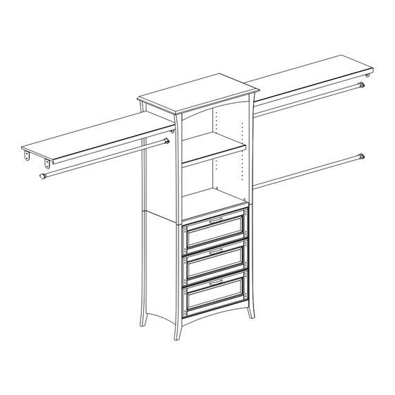
HARDWOOD CLOSET
Purchase Date _________________________
1
ITEM #0020720
SYSTEM
MODEL #WSCO-72C-AR
Advertisement

Subscribe to Our Youtube Channel
Related Manuals for Allen + Roth WSCO-72C-AR


Summary of Contents for Allen + Roth WSCO-72C-AR
- Page 1 ITEM #0020720 HARDWOOD CLOSET SYSTEM MODEL #WSCO-72C-AR ATTACH YOUR RECEIPT HERE Serial Number _____________________ Purchase Date _________________________ Questions, problems, missing parts? Before returning to your retailer, call our customer service department at 1-866-942-5362, 8:30 a.m. – 4:30 p.m., PST, Monday to Friday.
-
Page 2: Table Of Contents
TABLE OF CONTENTS Safety Information …………………………………………………………………………………..3 Package Contents ……………………………………………………………………………..…….. 4 Hardware Contents ……………………………………………………………………………...…... 5 Assembly Instructions ……………………………………………………………………………….. 7 Warranty …………………………………….………………………………...…...……………...…. 17 Replacement Parts List ……………………………………………………...…...…………...……. 17... -
Page 3: Safety Information
SAFETY INFORMATION Please read and understand this entire manual before attempting to assemble, operate or install the product. If you have any questions regarding the product, please call customer service at 1-866-942-5362, 8:30 a.m. – 4:30 p.m., PST, Monday to Friday. WARNING Maximum weights indicated. -
Page 4: Package Contents
PACKAGE CONTENTS PART DESCRIPTION QUANTITY PART DESCRIPTION QUANTITY Hutch Panel Left Base Panel Top Hutch Panel Right Base Panel Left Hutch Panel Top Base Panel Right Front Stretcher Base Panel Bottom Rear Stretcher Base Panel Back Adjustable Shelf Hutch Panel Bottom CAPPUCCINO UNIT Hutch Panel Back PART... -
Page 5: Hardware Contents
HARDWARE CONTENTS (shown actual size) M3 x 13 mm Sunk Screw M4 x 16 mm M3 x 16 mm Wood Screw Wood Screw Qty. 4 M4 x 25 mm Bolt Qty. 38 Qty. 96 Qty. 6 M4 x 38 mm Wood Screw Qty. - Page 6 HARDWARE CONTENTS (shown actual size) Wood Dowel Plastic Corner Shelf Holder L Bracket Qty. 20 Anchor Qty. 2 Qty. 4 Qty. 8 Qty. 14 Drawer Handle Qty. 3 PREPARATION Before beginning assembly of this product, make sure all parts are present. Compare parts with package contents list and hardware contents above.
-
Page 7: Assembly Instructions
ASSEMBLY INSTRUCTIONS Insert wood dowel (QQ) in holes without threaded inserts into base panel right (K). Attach base pan- el bottom (L) to base panel right (K) by connecting large cam lock (LL) with large cam bolt (MM). Operate cam kits in this way: 1) Screw cam bolts (MM) in base panel right (K) 2) Push cam locks (LL) in base panel bottom (L) 3) Connect both and secure cam locks (LL) - Page 8 ASSEMBLY INSTRUCTIONS Have base panel left (J) assembled by connecting large cam bolts (MM) with large cam locks (LL). After that, attach two plastic corners (RR) only to front corners using M4 x 16 mm wood screws (CC) to strengthen base structure.
- Page 9 ASSEMBLY INSTRUCTIONS Attach both drawer panel front (O) and drawer panel back (P) to drawer panel right (R) by connecting small cam bolts (OO) with small cam locks (NN); attach drawer panel left (Q) to both drawer panel front (O) and drawer panel back (P) by connecting small cam bolts (OO) with small cam locks (NN).
- Page 10 ASSEMBLY INSTRUCTIONS Assemble drawer bottom (S) to the bottom side of drawer frame using M3 x 16 mm wood screw (BB) through pilot holes. Hardware Used M3 x 16 mm x 16 Wood Screw Attach drawer handle (UU) to drawer panel face (N) using M4 x 25 mm bolts (DD).
- Page 11 ASSEMBLY INSTRUCTIONS Extend the drawer glide frames on both base panel left (J) and base panel right (K) out from the base. Align drawer glide frame and drawer tracks together. Slide the drawer glide tracks into the drawer glide frames until the drawer is completely closed.
- Page 12 ASSEMBLY INSTRUCTIONS Insert wood dowels (QQ) in holes without thread inserts into hutch panel right (B). Assemble both front stretcher (D) and rear stretcher (E) to hutch panel right (B) by connecting large cam bolts (MM) with large cam locks (LL). Operate cam kits in this way: 1) Screw cam bolts (MM) in hutch panel right (B)
- Page 13 ASSEMBLY INSTRUCTIONS Assemble hutch panel top (C) by using large cam bolts (MM), large cam locks (LL), and wood dowels (QQ). Make sure crown beveled edges are located in front. Operate cam kits in this way: 1) Screw cam bolts (MM) in hutch panel top 2) Push cam locks (LL) in both hutch panel left (A) and hutch panel right (B) 3) Connect both and secure cam locks (LL)
- Page 14 ASSEMBLY INSTRUCTIONS Insert wood dowels (QQ) in holes without thread inserts into both base panel right (K) and base panel left (J). Have both hutch and base connected using large cam bolts (MM) and large cam locks (LL). Operate cam kits in this way: 1) Screw cam bolts (MM) in both base panel right (K) and base panel left (J) as shown 2) Push cam locks (LL) in both hutch panel...
- Page 15 ASSEMBLY INSTRUCTIONS Attach four L brackets (SS) to both ends of long shelf (T) using M4 x 16 mm wood crews (CC). Level shelf in the desired location and mark the holes locations on the side wall and cabinet side. Drill holes at the marked locations on the wall using 3/8 in.
- Page 16 ASSEMBLY INSTRUCTIONS Level metal pole (U) at the desired location and mark the holes’ locations in the side wall and cabinet side; drill holes at the marked locations on the wall using 3/8 in. bit. Next, insert anchors into holes. Secure a closed pole holder (KK) to side wall using M4 x 38 mm wood screws (EE), and pole holder (JJ) to cabinet side using M4 x 16...
-
Page 17: Warranty
WARRANTY Warranty is restricted to original owner and proof of purchase will be required. Warranty is for one (1) year from date of purchase. Should the product be defective in material or workmanship or fail under normal use, we will repair or replace the unit at our discretion. Shipping charges to our warehouse are the responsibility of the customer. - Page 18 PART DESCRIPTION PART # Drawer Panel Face DPF1 Drawer Panel Front DPF2 Drawer Panel Back Drawer Panel Left Drawer Panel Right CAPPUCCINO UNIT Drawer Bottom PART DESCRIPTION PART # Long Shelf Metal Pole PART DESCRIPTION PART # PART DESCRIPTION PART # Large Cam Lock M3 x13 mm Sunk Screw 13SS...
Need help?
Do you have a question about the WSCO-72C-AR and is the answer not in the manual?
Questions and answers