Table of Contents
Advertisement
CIM-LINK Setup Guide
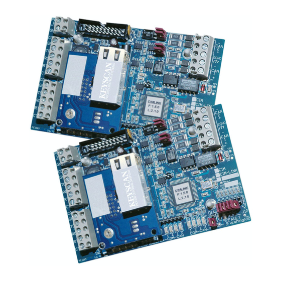
CIM-LINK modules, sold in sets of two, are used to establish ACU to ACU communication
between two or more communication loops over an Ethernet (TCP/IP) network for global
functions, such as global anti-pass back, global time zones, or global inputs and outputs.
This guide outlines how to connect the CIM-LINK modules and program the NETCOM2P
with the Keyscan NETCOM Program Tool utility. CIM-LINK modules only communicate over
a network (TCP/IP) using a NETCOM2P.
Before You Start
Verify that you have all the parts as outlined below.
Keyscan recommends reviewing this document and pre-planning where and how the
CIM-LINK modules are connected to create global communication within the access
control communication structure.
The NETCOM2Ps included with the CIM-LINK modules must be programmed with
static IP addresses, subnet masks, and, if applicable, gateways and Ethernet
connection types which you may have to obtain from the IT administrator
Ensure that the Keyscan NETCOM Program Tool utility, which is required for
programming the NETCOM2P and is located on the Keyscan Drivers and Utilities CD, is
installed on a PC or laptop that can be serially connected to the CIM-LINK/NETCOM2P
as outlined in the Program NETCOM2P section
Space is provided on a worksheet at the back of this setup guide for recording all
CIM-LINK jumper settings at all applicable access control units
Contents
Configuration
Jumper Settings & Power
Diagnostics
2
3
7
11
19
23
28
Figure 1 – CIM-LINK Modules
Parts List
CIM-LINK Modules
Serial Programming Cable
Keyscan Drivers & Utilities CD
2
2
1
1
Advertisement
Table of Contents

Related Manuals for Keyscan CIM-LINK


Summary of Contents for Keyscan CIM-LINK
- Page 1 CIM-LINK Setup Guide CIM-LINK modules, sold in sets of two, are used to establish ACU to ACU communication between two or more communication loops over an Ethernet (TCP/IP) network for global functions, such as global anti-pass back, global time zones, or global inputs and outputs.
- Page 2 Pre-Installation Keyscan suggests that you review the following material to ensure that you have the required firmware and software versions that support the CIM-LINK modules. CIM-LINK Requirements The CIM-LINK module requires the following control board firmware and software versions: Hardware - Aurora ...
- Page 3 CIM-LINK Configuration When using CIM-LINK modules, one communication loop must be configured as the master communication loop and all others as subordinate communication loops. When interconnecting two or more communication loops, install each pair of CIM-LINK modules as follows: ...
- Page 4 Figure 3 - CIM-LINK Modules Connecting Multiple Communication Loops Input A, Input B, Input C, and Input D programmed to fire the output in Building 1. Building 1 Input A Output Communication Loop - Master (Alarm/CCTV etc.) 1 CIM as Global Master on least busy OCB-8 or IOCB1616 ACU.
- Page 5 Single ACU panel communication Manager loop requires only a CIM-LINK module. See Figure 13 or CIM-LINK Figure 14 for - communicates with CIM-LINK – Building 2 connections. CIM-LINK J3 ON – Global Master J4 ON – Single ACU Mode Virtual Connection Building 2...
- Page 6 Single ACU panel communication Manager loop requires only a CIM-LINK module. See Figure 13 or CIM-LINK Figure 14 for - communicates with CIM-LINK – Building 2 connections. CIM-LINK J3 ON – Global Master J4 ON – Single ACU Mode Ethernet Virtual...
- Page 7 CAN Bus 1 – J5 & J6 – do not apply to the CIM-LINK module, leave OFF (terminate first and last CIM modules on CAN Bus 1) CAN Bus 2 – J7 & J8 – if the CIM-LINK module is the first or last unit, terminate with jumpers ON; otherwise leave jumpers OFF Power The method of powering the CIM-LINK module with the NETCOM2P depends on the type of communication loop they are connected on.
- Page 8 CIM-LINK Jumper Locations The CIM-LINK modules are jumpered as indicated in the table below depending on its function. Figure 6 – CIM-LINK Module Jumpers Jumper Legend Jumper Off Jumper On Off = 0 On = 1 CIM-LINK Module Jumper Locations...
- Page 9 NETCOMP plugged into SCKT1. Note on Global Message Filtering Jumpers J9 – J10 – J11 shorted in various combinations on the CIM-LINK module filter global messages as outlined in the table. Note the following global message filtering conventions: ...
- Page 10 Note As an option, the NETCOMP can be programmed off-site before installation providing you have a 12 VDC power supply that can be connected to the CIM-LINK’s TB4 power terminal. See Figure 7 or Figure 9 for connections. Temporary Programming Connections Review Figure 7 to Figure 10 for establishing a connection with the serial data cable and/or with the USB-SER adaptor from the PC/laptop to the NETCOM2P.
- Page 11 To program SCKT1 CTS1 NETCOM2P Jumper ON J12 COM2 Green Black NETCOMP Tx Data Diag RTS2 Rx Data B3 B2 B1 B0 Standoffs Power CTS2 Good 1 2 1 2 1 2 1 2 Fault PC106x KI-00319E-07-11 CIM-LINK Setup Guide...
- Page 12 B3 B2 B1 B0 Standoffs Power CTS2 Good 1 2 1 2 1 2 1 2 Fault PC106x Serial Data Cable with loose conductors PC or laptop with Keyscan NETCOM Program Tool Utility. KI-00492E-10-12 Keyscan Inc. A Member of the Kaba Group...
- Page 13 485 OUT 485 IN Green + TX - + RX - Black NETCOMP Tx Data Diag RTS2 Rx Data B3 B2 B1 B0 Standoffs Power CTS2 Good 1 2 1 2 1 2 1 2 KI-00320E-07-11 Fault PC106x CIM-LINK Setup Guide...
- Page 14 1 2 1 2 1 2 1 2 Fault PC106x Current Draw : CIM 150 mA + NETCOMP 140 mA = 290 mA PC or laptop with Keyscan NETCOM Program Tool Utility. KI-00493E-10-12 Keyscan Inc. A Member of the Kaba Group...
- Page 15 Place a jumper ON J12 on the CIM-LINK circuit board. Turn on the laptop or PC connected to the CIM-LINK. Connect the CIM-LINK to a power source or via the ribbon cable to H2 on the control board. Momentarily place a jumper on J1 RESET on the CIM-LINK.
- Page 16 Network equipment = 100Mbit/Half Duplex. 17. Click on the CIM-LINK Setup button. 18. Enter the IP address of the corresponding subordinate CIM-LINK’s NETCOM2P in the IP Address to Assign. 19. Enter 3001 in the Remote Port Number to Assign field.
- Page 17 Turn on the laptop or PC connected to the CIM-LINK module. Connect the CIM-LINK module to a power source or connect the ribbon cable to H2 on the control board. If using the latter method, ensure the control board has power from the DPS-15.
- Page 18 Momentarily short the Reset jumper on the NETCOM2P and follow the on-screen prompts. 17. If the PC/laptop and the CIM-LINK/NETCOM2P are connected to the network, you can PING the device to verify a network connection. Select Start PING and wait for the PING Status Result message –...
- Page 19 Operational Connections Refer to the following diagrams for connecting the CIM-LINK modules with NETCOM2Ps. Ensure that you have programmed the NETCOM2Ps with the Keyscan NETCOM Program Tool Utility before making permanent operating connections. Figure 11 – CIM-LINK Connected on Global Master (CIM 1) Communication Loop...
- Page 20 Figure 12 - CIM-LINK as Group Master on Subordinate Communication Loop IOCB (COM1) to network CPB/CB COMMS (COM4) Slave PC with Communication Manager COMMON AUX INPUTS - E Termination Jumpers ON 17 18 19 20 21 22 23 24 J5 & J6 / J7 & J8...
- Page 21 Figure 13 - CIM-LINK on a Single Communication Loop – Control Board has Network Connection PC/server with Communication Manager Current - Control Board 130 mA + NETCOMP 140 mA = 270 mA Control Board network (PC 109x) RS-232 shown with NETCOM2P plugged into M1 socket.
- Page 22 Figure 14 - CIM-LINK on a Single Communication Loop – Control Board has RS- 232 Serial Connection to Com Port on PC with Communication Manager Current - Control Board 130 mA Brown & White RS-232 5 conductor not used. Tape 22 AWG shielded cable back separately.
- Page 23 CIM-LINK Diagnostics The CIM-LINK unit has on-board diagnostic LEDS - B3 to B0 - which are designed to assist in troubleshooting communication difficulties. diagnostic LEDs during boot-up - initial power or Reset J1 data LEDs during operation are Tx – transmit Diagnostic Guidelines LEDs B3 –...
- Page 24 B3 – B0 Code 1 to 4 – basic initialization notices 5 (0101) – the CIM-LINK has entered NETCOMP program mode (LEDs will extinguish after approximately 1 second.) 8 (1000) – single ACU mode ...
- Page 25 Worksheet The attached worksheet can be used to record settings of ACU, CIM and CIM-LINK modules. We suggest making sufficient copies of the worksheet so you have a record of settings at each panel location. Circle appropriate settings or jumper pins (ON) and list network addresses.
- Page 26 This page is intentionally blank. Keyscan Inc. A Member of the Kaba Group...
- Page 27 This page is intentionally blank. CIM-LINK Setup Guide...
- Page 28 CIM-LINK Specifications Operating Voltage 12VDC Current Draw CIM-LINK 150 mA + NETCOM2P 140 mA = 290 mA Dimensions 4 5/8” x 3” (11.7 cm x 7.6 cm) Operating Environment Suitable for industrial and commercial applications. Operating temperatures: 5 C to 60...
Need help?
Do you have a question about the CIM-LINK and is the answer not in the manual?
Questions and answers