Table of Contents
Advertisement
Advertisement
Table of Contents

Related Manuals for Keyscan CA150


Summary of Contents for Keyscan CA150
- Page 2 Information and specifications in this document are subject to change without notice. Except for the benefit of installation and operation of the Keyscan access control system, no part of this documentation may be reproduced or transmitted in any form or by any means without the expressed written permission of Keyscan Inc.
-
Page 4: Table Of Contents
Restore Default Settings – Jumper J1 Clear Memory................. 49 System Reset – J6 ........................50 Door & AUX Outputs – Powered/Unpowered ..................50 Accessibility Output Relay ......................51 Keyscan Inc. A Member of the Kaba Group – CA150 Rev. B Installation Guide (07.15) - Page 5 Set IP Address on Access Control Board..................101 Program the CA150 On-board Ethernet Module ................103 CA150B Quick Reference ....................... 107 CA150B Specifications ........................109 Warranty ............................112 Index ............................113 Keyscan Inc. A Member of the Kaba Group – CA150 Rev. B Installation Guide (07.15)
-
Page 6: List Of Figures
Figure 35 - PoE Connections ........................ 60 Figure 36 – Power Supply Wiring ......................61 Figure 37 – Control Board Test Points – Voltages ................... 62 Keyscan Inc. A Member of the Kaba Group – CA150 Rev. B Installation Guide (07.15) - Page 7 Figure 65 – Location of System Configuration DIP Switches ..............101 Figure 66 – Temporary Programming Connection for Reverse Network ............ 102 Figure 67 – CA150B Control Board ...................... 107 Keyscan Inc. A Member of the Kaba Group – CA150 Rev. B Installation Guide (07.15)
-
Page 8: Foreword
Vantage – version 8.1.13 or higher If you are operating with a previous version of Keyscan software you can obtain the latest version at www.keyscan.ca or for Vantage at www.keyscanenterprise.ca. The CA150 is not compatible with any previous generation of Keyscan software. -
Page 9: About Powering The Ca150
The CA150 operates as a Class 0 PoE Powered Device (PD). As such, the CA150 requires the allocation of 15.4 Watts from the PoE switch or injector. Of the 15.4 Watts, the CA150 provides 680 mA at 12 volts –... - Page 10 The CA150 requires NETCOM Program Utility – version 6.0.18 or higher. Always use the latest NETCOM Program Utility on the enclosed Keyscan CD when programming the on-board Ethernet module. For an outline of requirements and procedures on configuring the CA150 for reverse network communication, see page 96.
-
Page 11: Locate & Mount The Ca150
Locate & Mount the CA150 Locate the area where the CA150 and, if required, the power supply, are going to be mounted. Follow the mounting procedures on the following page. Keyscan recommends a vertical mount on a solid, smooth surface. -
Page 12: Mounting Guidelines
Fasten the top 2 screws and the lower left screw until there is a gap of approximately 1/32” between each of the screw heads and the mounting surface Mount the CA150 so that the 3 keyway cutouts at the back of the enclosure are over the screw heads as shown in Figure 3 ... -
Page 13: Figure 3 - Mounting The Ca150
- Fasten and tighten the 4 screw in the lower right hole Keyway Left Cover Cutout (Do not remove.) CA150B Rev. B x3 for Keyway Knock-out KI-00323E-07-14 Cutouts Keyscan Inc. A Member of the Kaba Group – CA150 Rev. B Installation Guide (07.15) -
Page 14: Figure 4 - Ca150 Mount - Side View
3 against mounting screws are seated surface. at the top of the keyway cutouts. Keyway Cutout Keyway Cutout KI-00435E-12-11 Keyscan Inc. A Member of the Kaba Group – CA150 Rev. B Installation Guide (07.15) -
Page 15: Door Hardware & Readers
Consult with local authorities. Important In a PoE powered configuration, the CA150 supplies 680 mA at 12V (approximately 8 watts) to power all loads including readers, door strikes, request-to-exit PIR devices, etc. To power devices such as magnetic locks, the CA150 or the device must be powered from a dedicated +12V DC power supply. -
Page 16: Door Contacts, Exit Buttons, Auxiliary Inputs
(RTE - Request To Exit) Auxiliary Input Aux Input NO = Normally Open NC = Normally Closed KI-00122E-07-11 Keyscan Inc. A Member of the Kaba Group – CA150 Rev. B Installation Guide (07.15) -
Page 17: Readers
Shield not connected. Isolate with electrical tape. 6 conductors shielded 18 or 22 AWG Maximum 500 ft (152.4 m) To reader terminal on KI-00123E-07-11 Keyscan Inc. A Member of the Kaba Group – CA150 Rev. B Installation Guide (07.15) -
Page 18: Cables & Grounding
Ground the access control unit and shielded cables to a cold water pipe. Failing to ground the shields or using incorrect cables may cause noise or interference and result in improper card reads. Refer to Figure 7 – Grounding Access Control Units and Cables. Keyscan Inc. A Member of the Kaba Group – CA150 Rev. B Installation Guide (07.15) - Page 19 If terminating a RS-232 communication cable in the metal enclosure, ensure that the shield is insulated and connected to the ground lug. Keyscan suggests Alpha PVC 10516 - #16 clear tubing or a comparable tubing to insulate the shield. Do not connect the shield to GND on the RS-232 communication terminal block.
-
Page 20: Figure 7 - Grounding Access Control Units And Cables
*Note # 18 AWG Green (+ 12 VDC) +12V DC - required for either PoE or ungrounded power supply Power Supply - not required for grounded power supply KI-00324E-07-11 Keyscan Inc. A Member of the Kaba Group – CA150 Rev. B Installation Guide (07.15) -
Page 21: Terminate Wiring At The Acu
+12V DC power supply with a sufficient current rating is required. For more information on PoE, refer to page 9. Do not use PoE to power a magnetic lock or similar device. Either, power the CA150 control board or the mag lock from a dedicated +12V DC supply. - Page 22 Diodes must be installed and terminated at the door relay terminal on the CA150 for DC door strikes if the CA150 supplies power to the strike via the DC power input or via PoE, as illustrated in the following lock diagrams.
-
Page 23: Figure 8 - Terminate Magnetic Lock Under 500 Ma - Fail Safe
Set J8 & J9 to Powered is not a dry contact. CA150 Install diode at CA150 door terminal. Observe correct polarity. KI-00327E-11-12 Keyscan Inc. A Member of the Kaba Group – CA150 Rev. B Installation Guide (07.15) -
Page 24: Figure 9 - Terminate Magnetic Lock Over 500 Ma - Fail Safe
Set J8 & J9 to Unpowered may be required if fire contact is not a dry contact. Ensure all lock hardware complies with federal, state/provincial, and municipal fire codes. KI-00328E-11-12 Keyscan Inc. A Member of the Kaba Group – CA150 Rev. B Installation Guide (07.15) -
Page 25: Figure 10 - Terminate Door Strike - 500 Ma Or Less - Fail Safe
Set J8 & J9 to Powered may be required if fire contact is not a dry contact. CA150 Install diode at CA150 door terminal. Observe correct polarity. KI-00329E-11-12 Keyscan Inc. A Member of the Kaba Group – CA150 Rev. B Installation Guide (07.15) -
Page 26: Figure 11 - Terminate Door Strike - Over 500 Ma - Fail Safe
Keyscan recommends that power supplies have back-up batteries. * RB5 Keyscan isolation relay Set J8 & J9 to Unpowered may be required if fire contact is not a dry contact. KI-00330E-11-12 Keyscan Inc. A Member of the Kaba Group – CA150 Rev. B Installation Guide (07.15) -
Page 27: Figure 12 - Terminate Door Strike - Less Than 500 Ma - Fail Secure
Keyscan recommends that power supplies have back-up batteries. Set J8 & J9 to Powered CA150 Install diode at terminal block on CA150. Observe polarity. KI-00331E-11-12 Keyscan Inc. A Member of the Kaba Group – CA150 Rev. B Installation Guide (07.15) -
Page 28: Figure 13 - Terminate Door Strike - Over 500 Ma - Fail Secure
Keyscan recommends that power supplies have back-up batteries. Ensure all lock hardware complies with federal, state/ Set J8 & J9 to Unpowered provincial, and municipal fire codes. KI-00332E-11-12 Keyscan Inc. A Member of the Kaba Group – CA150 Rev. B Installation Guide (07.15) -
Page 29: Terminate Input Wiring
S2.8 = OFF S2.8 = ON S2.7 = ON S2.7 = ON to Door (-) to Door (+) to Door + to Door - KI-00333E-02-14 Keyscan Inc. A Member of the Kaba Group – CA150 Rev. B Installation Guide (07.15) -
Page 30: Figure 15 - Terminate Input Wiring - Rte Push Button
Examples of exit devices are exit push buttons or motion sensors (PIR) etc. When using a motion sensor (PIR) for an exit device, Keyscan recommends a PIR with a pulse output of 1/2 second and suited to its environment. -
Page 31: Figure 16 - Terminate Input Wiring - Rte Pir Motion Sensor
S2.8 = OFF S2.8 = ON S2.7 = ON S2.7 = ON to RTE - to RTE + to RTE - to RTE + Lens Lens KI-00335E-02-14 Keyscan Inc. A Member of the Kaba Group – CA150 Rev. B Installation Guide (07.15) -
Page 32: Figure 17 - Terminate Input Wiring Rte - Pir & Push Button
S2.8 = OFF S2.8 = ON S2.7 = ON S2.7 = ON to RTE - to RTE + to RTE - to RTE + KI-00336E-02-14 Keyscan Inc. A Member of the Kaba Group – CA150 Rev. B Installation Guide (07.15) -
Page 33: Figure 18 - Terminate Input Wiring - Ai/Si Inputs
The auxiliary alarm inputs may be connected to infrared sensors or to an existing alarm system with a normally-closed auxiliary output relay contact. The CA150 does not support global functions. Figure 18 – Terminate Input Wiring – AI/SI Inputs S2.7 and S2.8 set the... -
Page 34: Terminate Reader Wiring At Acu
Enclosure back. Cable in through knockout. Pre-alert (Blue) (BEEP) D1 (White) Reader terminal on control board D0 (Green) PWR (Red) GND (Black) (BEEP) Ground KI-00338E-07-11 Keyscan Inc. A Member of the Kaba Group – CA150 Rev. B Installation Guide (07.15) -
Page 35: Terminate Auxiliary Outputs With Hardware/Alarms
Do not assign a time zone to an auxiliary output if the output has previously been assigned to an alarm event. The alarm has priority over the time zone. The CA150 does not support global functions. Figure 20 – Terminate Auxiliary Output... -
Page 36: Dip Switch & Jumper Settings
The communication bit rate selection regulates the number of bits the control board processes per second. The control board may be set on one of its configurable bit rates. Ensure that the Keyscan Client software baud rate setting matches the control board’s bit rate when using a serial connection. If using the on-board Ethernet module, ensure the module is programmed with the corresponding control board bit rate. - Page 37 CA150 control board. S1.8 - Accessibility Output The CA150 can convert the AUX output to an Accessibility output for connection to an electro-mechanical door operator. When configured as an accessibility output, the output follows the accessibility door timer and the accessibility door held open settings in the Client software.
-
Page 38: Figure 21 - System Configuration Dip Switches S1.1 - S1.12
Factory-assigned serial # Only set DIP switch for alternate serial number if prompted in the Client software when adding a panel. Adds 1000 to factory-assigned serial # Keyscan Inc. A Member of the Kaba Group – CA150 Rev. B Installation Guide (07.15) - Page 39 For direct serial communication Future use Enables Ethernet operation mode For network communication Enables Ethernet program mode For programming the Ethernet module S1.12 Flash Program Memory Upgrade Keyscan Inc. A Member of the Kaba Group – CA150 Rev. B Installation Guide (07.15)
-
Page 40: Reader Configuration - Dip Switches S2.1 - S2.6
Keyscan’s 36-bit proprietary Wiegand format cards and tags, which include a manufacturer’s code, offer a high level of security. Keyscan tracks all its cards and tags. This ensures that no duplicate cards or tags are sold by Keyscan. When installing or upgrading a Keyscan access control system, we recommend our proprietary Keyscan 36-bit Wiegand format cards and tags, available in 125 kHz or 13.56 MHz formats, for a high level of... -
Page 41: Supported Keypad Wiegand Outputs
Client software’s Site Information screen. If a high volume of cards is involved, you may wish to connect a reader close to a PC with the Keyscan Client and use it as a designated card enrollment reader. You can access the Client help by pressing F1. -
Page 42: Figure 22 - Location Of Reader Format Dip Switches S2.1 - S2.6
Only reads the card bit CSN, 8-bit Checksum) serial number sector 26 to 48 Pass-through Medium - 1 1 1 1 1 1 Extended Large Card Format Keyscan Inc. A Member of the Kaba Group – CA150 Rev. B Installation Guide (07.15) - Page 43 0 0 0 1 0 0 Standard - Enter 0 (zero) for the batch number except facility code in the Client software to ignore the Keyscan Inc. A Member of the Kaba Group – CA150 Rev. B Installation Guide (07.15)
- Page 44 0 1 1 0 1 0 Standard Keyscan 36-bit Legacy 37-bit (37 Bit Corp 1 1 1 0 1 0 Standard H10302) & Standard 26-bit & Keyscan 36-bit Keyscan Inc. A Member of the Kaba Group – CA150 Rev. B Installation Guide (07.15)
- Page 45 Extended card number – hexadecimal = 1 – FFFFFFFFFFFF or decimal = 1 – 281474976710655 / Checked for extended number For other custom Wiegand protocol firmware or development, contact Keyscan technical support. Keyscan Inc. A Member of the Kaba Group – CA150 Rev. B Installation Guide (07.15)
-
Page 46: Figure 23 - Location Of Wiegand Card Bit Counter Leds
LED Wiegand Bit Counters The CA150 control board has LED Wiegand bit counters – 10s and 1s – to indicate the card’s binary bits. You must be able to observe the control board to do this procedure. To verify the binary bits, present the card or tag at the reader and count the number of times each LED blinks: ... -
Page 47: Supervision Mode Dip Switches S2.7 & S2.8
S2.7 & S2.8 - Supervision Mode DIP Switches The CA150 supports 3 types of input supervision as listed in the table below. DIP switches S2.7 and S2.8 regulate the level of supervision universally for the door contact, the request to exit, and the auxiliary/supervised alarm inputs on the control board. -
Page 48: System Software Mode - Dip Switches S2.9 & S2.10
DIP switches S2.9 and S2.10 select the Keyscan software application that is currently installed on the PC/server operating the CA150 control unit. Refer to Table 6 – System Software Mode DIP Switch on page 48 to configure the control board for the appropriate Keyscan software application. -
Page 49: Restore Default Settings - Jumper J1 Clear Memory
PC with a Keyscan Client software module so the Keyscan database is transferred to the control board’s on-board memory. If this is a new installation, enter the site information in the Keyscan Client software and then upload the Keyscan database information to the control board(s). Until you perform an upload from a Keyscan Client, the access control unit(s) will not function. -
Page 50: System Reset - J6
The door output relay and the AUX output relay are each fused at 500 mA. Each output has a set of jumpers which configures the output to source power from the CA150 or configures the output as a dry contact. When the output is configured as a dry contact, the connected device requires an independent power source. -
Page 51: Accessibility Output Relay
Accessibility Output Relay The AUX output relay on the CA150 can be set as an accessibility relay to connect with an electro-mechanical operator that opens and closes a door. System configuration DIP switch S1.8 regulates the relay as either an AUX output or accessibility output. -
Page 52: Figure 30 - Accessibility Output Relay Connections
Figure 30 – Accessibility Output Relay Connections System Configuration DIP Switch S1.8 = ON to door CA150B accessibility Control Board operator Cut View (+ 12 VDC) KI-00381E-02-14 Keyscan Inc. A Member of the Kaba Group – CA150 Rev. B Installation Guide (07.15) -
Page 53: Communication
Program Utility on the enclosed Keyscan CD when programming the on-board Ethernet module. Single Control Unit Communication Only The CA150 is designed as a single, stand-alone control unit; it does not support CIM, CB-485 or CPB-10-2 connections to other control units. The CA150 does not support global functions. -
Page 54: Figure 31 - Rs-232 Data Cable Connections
Typically, the red wire of the RS-232 cable, which is the transmit data output of the PC, is connected to the RD pin of most Keyscan products. Keyscan Inc. A Member of the Kaba Group – CA150 Rev. B Installation Guide (07.15) -
Page 55: Figure 32 - Communication - Rs-232 Direct Serial
Alpha PVC 10516 - #16 clear Green tubing or a comparable tubing to insulate the shield. Do not connect the shield to GND on a communication terminal block. KI-00351E-02-14 Keyscan Inc. A Member of the Kaba Group – CA150 Rev. B Installation Guide (07.15) -
Page 56: Figure 33 - Communication - Usb Adaptor/Pc
Alpha PVC 10516 - #16 clear Green tubing or a comparable tubing to insulate the shield. Do not connect the shield to GND on a communication terminal block. KI-00352E-02-14 Keyscan Inc. A Member of the Kaba Group – CA150 Rev. B Installation Guide (07.15) -
Page 57: Figure 34 - Communication - Ethernet
115,200 BPS – S1.2 = OFF 57,600 BPS – S1.2 = ON to network (+ 12 VDC) Left Cover CA150B Rev. B Ethernet terminal KEYSCAN INC. KI-00353E-07-14 Keyscan Inc. A Member of the Kaba Group – CA150 Rev. B Installation Guide (07.15) -
Page 58: Power-Up & Test Voltages
RTE port – 300 mA System Power-up Depending how the CA150 is connected for power – PoE (Class 0) or a +12V DC separate supply – refer to the relevant power up instructions. Important After the control board has been powered up for the first time, be sure to reset the factory defaults by performing a clear memory procedure outlined on page 49. - Page 59 Ethernet terminal on the CA150 control board. Within 5 seconds of establishing the connection, the CA150 should receive power from the PoE source and begin booting up. The system status LED illuminates in amber and the on-board piezo emits a beep.
-
Page 60: Figure 35 - Poe Connections
115,200 BPS – S1.2 = OFF 57,600 BPS – S1.2 = ON to network (+ 12 VDC) Left Cover CA150B Rev. B Ethernet terminal KEYSCAN INC. KI-00353E-07-14 Keyscan Inc. A Member of the Kaba Group – CA150 Rev. B Installation Guide (07.15) -
Page 61: Figure 36 - Power Supply Wiring
Ensure the right cover on the CA150 control board has been removed. Connect the +12V DC power supply to the POWER IN terminals (TB6) on the CA150. Upon applying power, the CA150 begins booting-up. The system status LED illuminates in amber and the on-board piezo emits a beep. -
Page 62: Control Board Voltage Test Points
Input points shorted to common return 0 VDC Figure 37 – Control Board Test Points – Voltages RST. MEM. (BEEP) WHITE GREEN (BEEP) WHITE GREEN KI-00356E-02-14 Keyscan Inc. A Member of the Kaba Group – CA150 Rev. B Installation Guide (07.15) -
Page 63: Test Points - Communication Terminals
TD is an ACU generated voltage (-) 10 VDC RD is a PC generated voltage Used for modems only Figure 38 – Control Board Communication Test Points Left Cover KI-00357E-05-12 Keyscan Inc. A Member of the Kaba Group – CA150 Rev. B Installation Guide (07.15) -
Page 64: Diagnostics
Diagnostics The CA150 has communication and system status LEDs on the left side of the control unit for diagnostics. Communication LEDs The CA150 has on-board LEDs for communication diagnostics outlined in the table below. If calling Keyscan for technical support, indicating the state of the LED assists our technicians in isolating potential difficulties. -
Page 65: System Status Led
The control board’s last communication with the Client software was 3 minutes or greater. Green – solid The control board has communicated to the Client software since its last system reset or clear memory Keyscan Inc. A Member of the Kaba Group – CA150 Rev. B Installation Guide (07.15) -
Page 66: Figure 40 - Location Of System Status Led
Left Cover SYSTEM COMMUNICATION STATUS STATUS TD 1 RD 1 TD 2 RD 2 SYSTEM SERVER INPUTS/ RS-232 (TB5) RS-485 ETHERNET System (TB7) Status KI-00359E-05-12 Keyscan Inc. A Member of the Kaba Group – CA150 Rev. B Installation Guide (07.15) -
Page 67: Keyscan / Hid Readers
Keyscan / HID Readers This section reviews typical connections for Keyscan readers and HID readers. Wiring diagrams are on the following pages. Refer to the appropriate diagram for specific reader connections. Be sure to use a cable that complies with the reader’s wiring specifications. - Page 68 See OEMs manual for operational details and recommendations. The following diagrams illustrate HID readers with dual LEDs. On models 5365, 5395, and Keyscan Inc. A Member of the Kaba Group – CA150 Rev. B Installation Guide (07.15)
- Page 69 S16 – 5 OFF single LED = 06 C1 Beep When the pre-alert wire is connected to C1 (Beep) on the reader terminal, the reader will also sound on an “alarm tripped”. Keyscan Inc. A Member of the Kaba Group – CA150 Rev. B Installation Guide (07.15)
-
Page 70: Figure 41 - Keyscan K-Prox2 (125 Khz)
(BEEP) LED (Brown) 6 conductors - shielded 22 AWG D1 (White) Maximum 500 ft D0 (Green) (152.4 m) PWR (Red) GND (Black) Shield Ground KI-00360E-07-13 Keyscan Inc. A Member of the Kaba Group – CA150 Rev. B Installation Guide (07.15) -
Page 71: Figure 42 - Keyscan K-Van Proximity Reader (125 Khz)
(BEEP) LED (Brown) 6 conductors - shielded 22 AWG D1 (White) Maximum 500 ft D0 (Green) (152.4 m) PWR (Red) GND (Black) Shield Ground KI-00361E-07-13 Keyscan Inc. A Member of the Kaba Group – CA150 Rev. B Installation Guide (07.15) -
Page 72: Figure 43 - Keyscan K-Kpr Keypad / Proximity Reader (125 Khz)
(BEEP) LED (Brown) 6 conductors - shielded 22 AWG D1 (White) Maximum 500 ft (152.4 m) D0 (Green) PWR (Red) GND (Black) Shield Ground KI-00362E-07-13 Keyscan Inc. A Member of the Kaba Group – CA150 Rev. B Installation Guide (07.15) -
Page 73: Figure 44 - Keyscan K-Smart Reader
Isolate with shielded 22 AWG (BEEP) electrical tape. Maximum 500 ft LED (Brown) (152.4 m) D1 (White) D0 (Green) PWR (Red) GND (Black) Shield Ground KI-00363E-06-12 Keyscan Inc. A Member of the Kaba Group – CA150 Rev. B Installation Guide (07.15) -
Page 74: Figure 45 - Hid-5395 Wiring
(BEEP) LED (Orange) 6 conductors - shielded 22 AWG D1 (White) Maximum 500 ft (152.4 m) D0 (Green) PWR (Red) GND (Black) Shield Ground KI-00364E-07-11 Keyscan Inc. A Member of the Kaba Group – CA150 Rev. B Installation Guide (07.15) -
Page 75: Figure 46 - Hid 5365 / 6005 Wiring
(BEEP) LED (Orange) 6 conductors - shielded 22 AWG D1 (White) Maximum 500 ft (152.4 m) D0 (Green) PWR (Red) GND (Black) Shield Ground KI-00365E-07-11 Keyscan Inc. A Member of the Kaba Group – CA150 Rev. B Installation Guide (07.15) -
Page 76: Figure 47 - Hid 5455 Wiring
The HID 5355 is suitable for indoor and outdoor use. Maximum read range at 12VDC – ProxCard II card is 9" (22 cm) – ISOProxII card is 8" (20 cm). Keyscan Inc. A Member of the Kaba Group – CA150 Rev. B Installation Guide (07.15) -
Page 77: Figure 48 - Hid 5375 Wiring
HID 5375 operates at 12 VDC or 24 VDC. Refer to HID literature for correct jumper settings. If configured for 12 VDC, do not connect to 24 VDC power supply, otherwise damage to the reader circuit board will result. Keyscan Inc. A Member of the Kaba Group – CA150 Rev. B Installation Guide (07.15) -
Page 78: Figure 49 - Hid 5355Kp Wiring
D0 (Green) PWR (Red) GND (Black) Shield Ground KI-00368E-07-11 Note on HID 5355 KP Reader/Keypad/LED ordered as 00 (4 bit burst) example 5355AGK00 (Red/Green colour) Keyscan Inc. A Member of the Kaba Group – CA150 Rev. B Installation Guide (07.15) -
Page 79: Figure 50 - Hid Iclass Keyr10
D1 (White) Rev A – 18 AWG Rev B & Rev C – 18 or 22 AWG D0 (Green) PWR (Red) GND (Black) Shield Ground KI-00369E-10-13 Keyscan Inc. A Member of the Kaba Group – CA150 Rev. B Installation Guide (07.15) -
Page 80: Figure 51 - Hid Iclass Keyr40
D1 (White) Rev A – 18 AWG Rev B & Rev C – 18 or 22 AWG D0 (Green) PWR (Red) GND (Black) Shield Ground KI-00370E-10-13 Keyscan Inc. A Member of the Kaba Group – CA150 Rev. B Installation Guide (07.15) -
Page 81: Figure 52 - Hid Iclass Keyrw400
Maximum 500 ft (152.4 m) D1 (White) Rev A – 18 AWG Rev C – 18 or 22 AWG D0 (Green) PWR (Red) GND (Black) Shield Ground KI-00371E-10-13 Keyscan Inc. A Member of the Kaba Group – CA150 Rev. B Installation Guide (07.15) -
Page 82: Figure 53 - Hid Iclass Keyrk40
D0 (Green) PWR (Red) GND (Black) Shield Ground KI-00372E-10-13 Note on HID iClass KEYRK40 Reader/Keypad/LED ordered as 00 (4 bit burst) – example 6131AKN00100 (Red/Green colour) Keyscan Inc. A Member of the Kaba Group – CA150 Rev. B Installation Guide (07.15) -
Page 83: Figure 54 - Hid Iclass R10 Series
Pre-alert (Yellow) (BEEP) LED (Orange) 6 conductors shielded 22 AWG D1 (White) Maximum 500 ft (152.4 m) D0 (Green) PWR (Red) GND (Black) Shield Ground KI-00512E-11-13 Keyscan Inc. A Member of the Kaba Group – CA150 Rev. B Installation Guide (07.15) -
Page 84: Figure 55 - Hid Iclass R15 Series
Pre-alert (Yellow) (BEEP) LED (Orange) 6 conductors shielded 22 AWG D1 (White) Maximum 500 ft (152.4 m) D0 (Green) PWR (Red) GND (Black) Shield Ground KI-00513E-11-13 Keyscan Inc. A Member of the Kaba Group – CA150 Rev. B Installation Guide (07.15) -
Page 85: Figure 56 - Hid Iclass R40 Series
(BEEP) LED (Orange) 6 conductors – shielded 22 AWG D1 (White) Maximum 500 ft (152.4 m) D0 (Green) PWR (Red) GND (Black) Shield Ground KI-00514E-11-13 Keyscan Inc. A Member of the Kaba Group – CA150 Rev. B Installation Guide (07.15) -
Page 86: Figure 57 - Hid Iclass Rk40 Series
Pre-alert (Yellow) (BEEP) LED (Orange) 6 conductors – shielded 22AWG Maximum 500 ft (152.4 m) D1 (White) D0 (Green) PWR (Red) GND (Black) Shield Ground KI-00515E-01-13 Keyscan Inc. A Member of the Kaba Group – CA150 Rev. B Installation Guide (07.15) -
Page 87: Indala Readers
AC switching relays can create EMI noise. Readers mounted on a metal surface can reduce the read range. See the Indala manual for recommendations. Keyscan Inc. A Member of the Kaba Group – CA150 Rev. B Installation Guide (07.15) -
Page 88: Figure 58 - Indala Px 603 And Px 605 Wiring
(BEEP) LED (Brown) 6 conductors - shielded 22 AWG D1 (White) Maximum 500 ft D0 (Green) (152.4 m) PWR (Red) GND (Black) Shield Ground KI-00373E-07-11 Keyscan Inc. A Member of the Kaba Group – CA150 Rev. B Installation Guide (07.15) -
Page 89: Figure 59 - Indala Px610 Wiring
CA150 Reader Terminal shielded 22 AWG Maximum 500 ft (152.4 m) (BEEP) Brown D1 (White) D0 (Green) Shield GND (Black 2) Black 1 ACU Ground Lug KI-00374E-07-11 Keyscan Inc. A Member of the Kaba Group – CA150 Rev. B Installation Guide (07.15) -
Page 90: Figure 60 - Indala Px 620 Wiring
The PX 620 is factory tuned. If a PX 620 requires tuning, tune only once. Excessive tuning may cause the reader to permanently malfunction. Refer to the Indala documentation for instructions on tuning. Keyscan Inc. A Member of the Kaba Group – CA150 Rev. B Installation Guide (07.15) -
Page 91: Figure 61 - Indala Pxk 501 Wiring
PWR (Red) GND (Black) Shield Ground KI-00376E-07-11 Note on Indala PXK 501 Wiring Reader/Keypad/LED ordered as 8 bit burst – example FP5061B-8 Bit Burst (Red only) Keyscan Inc. A Member of the Kaba Group – CA150 Rev. B Installation Guide (07.15) -
Page 92: Program On-Board Ethernet Module
– Configure CA150 for Reverse Network Communication. NETCOM Program Utility The CA150 Rev. B control board requires NETCOM Program Utility – version 6.0.18 or higher. Always use the latest NETCOM Program Utility on the enclosed Keyscan CD when programming the on-board Ethernet module. -
Page 93: Figure 62 - Temporary Connection For Programming The Ethernet Module
Connect the serial data cable from the PC/laptop to the RS-232 terminal on the CA150 as shown in the following illustration. If using Keyscan’s optional USB-SER Adaptor, you may also require a USB cable. Figure 62 - Temporary Connection for Programming the Ethernet Module... - Page 94 Ethernet Connection Type from automatic negotiation. (The Ethernet Connection Type is the network speed & duplex setting). Set the CA150 baud rate so it matches the network equipment setting. If the network equipment was on an automatic setting, then reconfigure both the network equipment, which may include routers or switches, and the CA150 Rev.
- Page 95 16. Click on the Program CA150 Rev. B button. 17. From the Program CA150 Rev. B Device via Serial Connection warning box, click on the OK button. 18. Momentarily place a jumper on J6 to reset the unit, or re-cycle the power. Wait while the Ethernet module is programmed.
-
Page 96: Configure Ca150 For Reverse Network Communication
If you have not purchased a K-RN, V-RN or AUR-RNx license, do not configure the CA150 Rev. B for reverse network communication. - Page 97 Programmed with static IP address Module or if using DHCP server dynamic IP Port # of Host PC/server Same encryption key/bit setting as host location Keyscan Inc. A Member of the Kaba Group – CA150 Rev. B Installation Guide (07.15)
-
Page 98: Figure 63 - Example Of Internet/Intranet/Wan With Router Or End Point External Ip
Port: 3001 - Port: 3001 (May also include an alternate Encryption Key: 12345678 KI-00459E-02-14 12345678 12345678 12345678 host router external IP address if available) Keyscan Inc. A Member of the Kaba Group – CA150 Rev. B Installation Guide (07.15) -
Page 99: Figure 64 - Lan With No Public Exposure
Reverse Network Programming: Internal Static IP: 192.168.0.4 - PC/Server internal IP: Encryption Key: 12345678 192.168.0.2 12345678 12345678 12345678 RN Port: 3001 RN Port: 3001 KI-00460E-02-14 Keyscan Inc. A Member of the Kaba Group – CA150 Rev. B Installation Guide (07.15) -
Page 100: Before You Start
Know the CA150’s baud rate setting – 57,600 BPS or 115,200 BPS Know the PC/laptop COM port with the serial data cable connected to the CA150 for programming the on- board Ethernet module Have an encryption key which must be coordinated with the host location so both keys are the same ... -
Page 101: Set System Configuration Dip Switches
S1.2 Set IP Address on Access Control Board This procedure requires Keyscan’s Hyper Terminal application on a PC or laptop that can connect with the access control unit. Keyscan’s Hyper Terminal application is accessible from the NETCOM Program Utility on the Keyscan Divers &... -
Page 102: Figure 66 - Temporary Programming Connection For Reverse Network
Connect the serial data cable from the PC or laptop to the RS-232 terminal on the CA150 control board as indicated in the diagram. If the CA150 is already connected for RS-232 communication with a direct serial connection to a PC, that PC may be used to program the control board with the IP address. -
Page 103: Program The Ca150 On-Board Ethernet Module
11. From the HyperTerminal menu, select 1) Set Primary IP Address. 12. Enter the IP address of the host’s router, end point, or PC/server with the Keyscan reverse network communication application depending on the network setup. - Page 104 Rev. B control board has DIP switches.) From the CA150 Rev. B Program Settings screen, enter the IP address assigned to the CA150’s on-board Ethernet module in the IP Address to Assign field. If using DHCP, enter 0.0.0.0 in the IP Address field.
- Page 105 11. The Discovery Port 77FE is disabled by default. Keyscan recommends that you leave it on the default setting. This function is principally for troubleshooting communication difficulties. 12. Click on a radio button that corresponds to the encryption bit setting of the host location – 128 Bit, 192 Bit or 256 Bit.
- Page 106 Do you wish to continue?’ warning box, click on the Yes button. 20. From the Program CA150 Rev. B Device via Serial Connection warning box, click on the OK button. 21. Momentarily place a jumper on J6 to reset the board, or re-cycle the power. Wait while the Ethernet module is programmed.
-
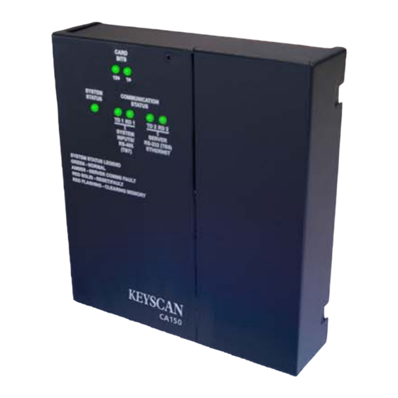
Page 107: Ca150B Quick Reference
AMBER - SERVER COMMS FAULT RED SOLID - RESET/FAULT RED FLASHING - CLEARING MEMORY (+ 12 VDC) KEYSCAN INC. CA150B Rev. B KEYSCAN CA150 KI-00382E-07-14 Keyscan Inc. A Member of the Kaba Group – CA150 Rev. B Installation Guide (07.15) - Page 108 S1.10 – Switch ON / S1.11 – switch ON RS-485 For future use Control Board Test See Table 9 on page Voltages Communication Test See Table 10 on page Voltages Keyscan Inc. A Member of the Kaba Group – CA150 Rev. B Installation Guide (07.15)
-
Page 109: Ca150B Specifications
CA150B Specifications The CA150 is designed as a single, stand-alone control unit; it does not support CIM, CB-485 or CPB-10-2 connections to other control units. The CA150 does not support global functions. The table below outlines CA150B specifications. Table 18 - CA150B Specifications... - Page 110 KEYSCAN systems are factory defaulted for KEYSCAN's proprietary 36-bit Wiegand format cards. KEYSCAN systems can be modified to recognize a wide range of additional access card formats. Some of these formats are proprietary to other system manufacturers. Some other formats, notably 26-bit Wiegand, are “open”.
- Page 111 This page is intentionally blank. Keyscan Inc. A Member of the Kaba Group – CA150 Rev. B Installation Guide (07.15)
-
Page 112: Warranty
Seller’s Right of Possession In addition to all remedies Keyscan may possess, Keyscan shall have the right at any time for credit reasons or because of buyer’s defaults, to withhold shipments in whole or in part, to recall goods in transit, retake same and repossess all goods which may be stored, without the necessity of taking any other action. -
Page 113: Index
Waiver of Liability, 110 PoE power supply, 58 Wiegand bit counter LEDs, 46 Power over Ethernet maximum current, 21 power up fail-safe, 22 procedures, 58 fail-secure, 22 Keyscan Inc. A Member of the Kaba Group – CA150 Rev. B Installation Guide (07.15)
Need help?
Do you have a question about the CA150 and is the answer not in the manual?
Questions and answers