Table of Contents
Advertisement
Quick Links
Advertisement
Table of Contents

Related Manuals for Maico MA 2 Series


Summary of Contents for Maico MA 2 Series
- Page 1 Operation Manual MA 25/MA 25e MA 27/MA 27e...
-
Page 2: Table Of Contents
Operation Manual MA 25/MA 25e MA 27/MA 27e Table of Contents 1 Introduction ......................3 1.1 General .......................... 3 1.2 Intended Use Statement ....................3 1.3 Indications for Use Statement ..................3 1.4 Contraindications of Use ....................3 1.5 Features and Benefits of the MA 25/MA 25e and MA 27/MA 27e ......... 4 1.6 Description ........................ - Page 3 Copyright © 2017 MAICO Diagnostics All rights reserved. No part of this publication may be reproduced or transmitted in any form or by any means without the prior written permission of MAICO Diagnostics. The information in this publication is proprietary to MAICO Diagnostics.
-
Page 4: Introduction
1.1 General Thank you for selecting one of our quality products from the MAICO family range. The MA 25/MA 25e and MA 27/MA 27e are designed and manufactured to meet all quality and safety requirements, and has been certified with the CE-Marking according to Medical Device Directive”... -
Page 5: Features And Benefits Of The Ma 25/Ma 25E And Ma 27/Ma 27E
Operation Manual MA 25/MA 25e MA 27/MA 27e 1.5 Features and Benefits of the MA 25/MA 25e and MA 27/MA 27e 1.5.1 General Information About the MA 25/MA 25e and MA 27/MA 27e The MA 25/MA 25e and the MA 27/MA 27e gives you the benefit of: ... -
Page 6: For Your Safety
2.1 How to Read this Operation Manual This Operation Manual contains information pertinent to the use of the MAICO device system including safety information as well as maintenance and cleaning recommendations. -
Page 7: Customer Responsibility
MAICO. NOTE: Customer responsibility includes proper maintenance and cleaning of the device (see sections 3.2 and 3.3). Breach of the customer responsibility can lead to limitations of Manufacturer’s Liability and Warranty (see sections 2.3 and 3.1). -
Page 8: Regulatory Symbols
Operation Manual MA 25/MA 25e MA 27/MA 27e 2.4 Regulatory Symbols The following Table 1 gives an explanation of the symbols used on the device itself, on the packaging and the accompanying documents including the Operation Manual. Table 1 Regulatory Symbols REGULATORY SYMBOLS SYMBOL DESCRIPTION... -
Page 9: General Precautions
No modifications of the equipment are allowed by anyone other than a qualified MAICO representative. Modification of the equipment could be hazardous. No part of the equipment can be serviced or maintained while in use with the patient. - Page 10 To avoid the risk of electric shock, this equipment must only WARNING be connected to the medical power supply originally delivered by MAICO. Using another power supply can also lead to electrical damage on the device. In order to maintain a high level of safety and to ensure the...
-
Page 11: Device Control
Operation Manual MA 25/MA 25e MA 27/MA 27e 2.7 Device Control The user of the device should perform a subjective device check once a week according ISO 8253-1. See section 6.7 for a checklist. For annual calibration please see sections 2.5 and 3.1 2.8 Electromagnetic Compatibility (EMC) Electrostatic discharge (ESD) according to IEC 61000-4-2. -
Page 12: Warranty, Maintenance And After-Sales Service
3.1 Warranty The MAICO device is guaranteed for at least one year. Ask your authorized local distributor for more information. This warranty is extended to the original purchaser of the device by MAICO through... -
Page 13: Disposables
In case of re-use of the single-use equipment you WARNING enhance the risk of cross contamination! In case you want to purchase further disposables, please contact MAICO or your local distributor. 3.5 Accessories/Replacement Parts Some reusable components are subject to wear with use over time. MAICO recommends that you keep these replacement parts available (as appropriate for your MA 25/MA 25e/MA 27/MA 27e device configuration). -
Page 14: Recycling And Disposal
Within the European Union it is illegal to dispose of electric and electronic waste as unsorted municipal waste. According to this, all MAICO products sold after August 13, 2005, are marked with a crossed-out wheeled bin. Within the limits of Article (9) of DIRECTIVE 2002/96/EC on waste electrical and electronic equipment (WEEE), MAICO has changed their sales policy. -
Page 15: Unpacking And Hardware Orientation
Operation Manual MA 25/MA 25e MA 27/MA 27e 4 Unpacking and Hardware Orientation This section provides information on: unpacking the system components becoming familiar with the hardware inclusive connections how to store the device 4.1 Unpacking the System Check Box and Contents for Damage ... -
Page 16: Hardware And Accessories
Operation Manual MA 25/MA 25e MA 27/MA 27e Table 2 Available Components Available Components AC Headphones DD45*. AC Headphones DD45 with HB-7-headband* Holmco 8103 Headphones* DD65 Headphones* AC Power Adapter, UE24WCP Type USB cable Operation Manual Quick Guide Patient Response Switch* Only for MA 25/MA 25e: Carrying bag 3 batteries inside the device... - Page 17 Operation Manual MA 25/MA 25e MA 27/MA 27e 4.2.2 Use of Equipment After Transport and Storage Make sure the device is functioning correctly before use. If the device has been stored in a colder environment (even for shorter time) allow the device to become acclimatized.
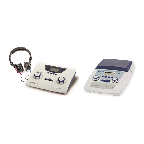
- Page 18 Operation Manual MA 25/MA 25e MA 27/MA 27e MA 27/MA 27e Figure 2 shows the MA 27/MA 27e device. The device has a main device layout, a case to store headsets and cables and a handle to easily carry the device (Figure 3). The connections are located in the case (Figure 4).
- Page 19 Operation Manual MA 25/MA 25e MA 27/MA 27e Connections MA 27/MA 27e MA 25/MA 25e Figure 7 Figure 6 Table 4 Explanation of the Connections CONNECTIONS Socket for left headphone jack (blue) Socket for right headphone jack (red) Socket for patient response switch Socket for external power supply UE24WCP Type 4.2.5 Only for MA 25/MA 25e: Battery Compartment For battery driven use of the MA 25/MA 25e 3x AA batteries have to be placed in the...
- Page 20 Operation Manual MA 25/MA 25e MA 27/MA 27e Table 5 PC-Connections PC CONNECTIONS PC Connection 1: PC Connection 2: Medical device – Medical Device Medical device – Non-Medical Device PC Connection 3: PC Connection 4: Medical device – Non-Medical Device Medical device –...
-
Page 21: Operating The Device
Operation Manual MA 25/MA 25e MA 27/MA 27e 5 Operating the Device This section offers you information about: how to get started with the device the device layout the display the function keys performing Tone Audiometric testing ... -
Page 22: Function Keys
Operation Manual MA 25/MA 25e MA 27/MA 27e 5.1.3 Switching the Device On and Off NOTE: All the cables and accessories have to be connected before the instrument is switched on. Power on is only possible if headphones are completely plugged-in! NOTE: The warm up time for the device including boot up process takes about 10 minutes. -
Page 23: Screens
Operation Manual MA 25/MA 25e MA 27/MA 27e Table 8 Explanation of Function Keys F-key Label MA 25e/MA 27e function Del All Deletes all thresholds stored in the internal memory of the MA 25e/MA 27e. Not H. Stores a Not Heard threshold point. Thres Displays the L/R thresholds stored in the internal memory of the MA 25e/27e (Figure 14). -
Page 24: Performing Tone Audiometric Tests
Operation Manual MA 25/MA 25e MA 27/MA 27e The icon will change depending on whether the instrument is powered via an external source (power supply or USB connection to computer) or batteries. The device is plugged into a power source. When powered by batteries, the battery icon will change depending on the battery power level. -
Page 25: Tone Setup Menu
Operation Manual MA 25/MA 25e MA 27/MA 27e Ensure that the headphones are positioned correctly: red phone on the right ear, blue phone on the left ear. Adjust the headband of the headphones so that the earphones are positioned at the correct height (i.e. the sound output grid exactly facing the ear canal). Prior to hearing threshold level measurements, the following instructions should be given. - Page 26 Operation Manual MA 25/MA 25e MA 27/MA 27e Table 9 Explanation of Function Keys in Setup Menu Function key Label Description Change To change highlighted setting. ↑ To browse up in the setup menu. ↓ To browse down in the setup menu. Save To save setting and go back to previous screen.
- Page 27 Operation Manual MA 25/MA 25e MA 27/MA 27e Setup Menu Description Press Change to toggle between Eng. (English), Ger. Language (German), Spa. (Spanish), Fre. (French) and Dut. (Dutch). Press Change to toggle between settings ranging from 0 (low LCD Contrast contrast) to 7 (strong contrast).
-
Page 28: Managing Test Results
Operation Manual MA 25/MA 25e MA 27/MA 27e Hughson-Westlake Test (HW) The MA 25e and MA 27e incorporate the Hughson-Westlake test (HW). The automation of this test is configured in the Hughson-Westlake test setup menu. Press Change to access the Hughson-Westlake Tests setup menu. Press Change again to enter the single setting options. - Page 29 Operation Manual MA 25/MA 25e MA 27/MA 27e Request Measurement (Figure 14, 1) button appears. Click on Request Measurement and the tone audiometry values are transferred and displayed on the PC screen. Figure 14 8104818 Rev. 4 19/10/2017...
-
Page 30: Technical Data
General Information About Specifications The performance and specifications of the device can only be guaranteed if it is subject to technical maintenance at least once per year. MAICO Diagnostics puts diagrams and service manuals at the disposal of authorized service companies. STANDARDS... - Page 31 Humidity 10 % to 95 % (non-condensing) Calibration Calibration information and instructions are located in the MA 25/MA 25e/MA 27/MA 27e Service Manual. Air Conduction DD45: MAICO Standard Values DD65: MAICO Standard Values Holmco 8103: PTB Standard Values Transducers –...
-
Page 32: Connections
Operation Manual MA 25/MA 25e MA 27/MA 27e Dimensions MA 25/MA 25e: 225 mm x 180 mm x 55 mm / 8.9 in x 7.1 in x 2.2 in MA 27/MA 27e: 255 mm x 370 mm x 150 mm / 10 in x 14.5 in x 6 in Display MA 25/MA 25e: 38.1 mm x 50.8 mm / 1.5 in x 2 in, Monochrome... -
Page 33: Pin Assignment
Operation Manual MA 25/MA 25e MA 27/MA 27e 6.3 Pin Assignment SOCKET CONNECTOR PIN 1 PIN 2 PIN 3 Left Ground Signal Right 6.3 mm Mono Pat. Resp. USB A (OUT) USB B (IN) 1. +5 VDC 1. +5 VDC 2. - Page 34 Operation Manual MA 25/MA 25e MA 27/MA 27e Table 15 Reference Values for Stimulus Calibration REFERENCE VALUES FOR STIMULUS CALIBRATION Reference equivalent threshold sound pressure level [RETSPL, dB re. 20 Pa] Fre- according to ISO 389-1 with coupler IEC 60318-3 quency [Hz] DD45...
- Page 35 [Y/N] Phones Headset Audiometric Headset Radioear DD45 L and R output Patient Patient response switch MAICO APS3 DC level Resp. UE24WCP- Power Supply Fuhua USB/DC-in DC level 050250SPA *To ensure compliance with the EMC requirements as specified in IEC 60601-1-2, iT is essential to use only the follow.
- Page 36 Operation Manual MA 25/MA 25e MA 27/MA 27e Surge +1 kV differential mode +1 kV differential mode Power supply quality should be that of a typical commercial or residential IEC 61000-4-5 +2 kV common mode environment. +2 kV common mode Voltage dips, short <...
-
Page 37: Electrical Safety, Emc And Associated Standards
Operation Manual MA 25/MA 25e MA 27/MA 27e 6.6 Electrical Safety, EMC and Associated Standards 1. UL/IEC/EN 60601-1: Medical Electrical Equipment, Part 1 General Requirements for Safety 2. CAN/CSA-C22.2 No. 60601-1: Medical Electrical Equipment, Part 1 General Requirements for Safety Electrical Equipment for Laboratory Use 3. -
Page 38: Checklist For Subjective Audiometer Testing
Operation Manual MA 25/MA 25e MA 27/MA 27e 6.7 Checklist for subjective Audiometer Testing 8104818 Rev. 4 19/10/2017... - Page 39 Specifications are subject to change without notice. MAICO Diagnostics GmbH Diagnostic Group LLC DBA MAICO Diagnostics Sickingenstr. 70-71 10393 West 70 Street 10553 Berlin Eden Prairie, MN 55344 Germany United States Tel.: + 49 30 / 70 71 46-50 Tel.: +1 (888) 941 4201...
Need help?
Do you have a question about the MA 2 Series and is the answer not in the manual?
Questions and answers