Table of Contents
Advertisement
Quick Links
Advertisement
Table of Contents

Related Manuals for LONCIN WG6500M-1


Summary of Contents for LONCIN WG6500M-1
- Page 2 This Manual should be considered a permanent part of the generator and should remain with it if it is resold. Loncin adheres to a strategy of sustainable development, so Loncin reserves the right to make changes or improvements without notice to any product described in this publication.
- Page 3 Safety Warnings Personal and property safety of you and other persons are of great concern to us. Please carefully read the each safety warning preceded by the symbol and each safety indication preceded by the symbol of , details of which are as follows: You WILL BE VERY SERIOUSLY HURT if you don’t follow instructions.
-
Page 5: Table Of Contents
Contents Contents I. Safety ························································································································· 2 II. Brief introduction of functions ···················································································· 6 III. Description of the set’s parts and components and their functions ·························· 7 Engine switch ········································································································· 8 Fuel switch ············································································································· 8 Choke switch ········································································································· 8 Recoil starter ·········································································································· 9 AC circuit breaker ··································································································... -
Page 6: Safety
Safety I. Safety Please carefully read and understand this Manual before operating the engine; safe operation procedures can help you avoid personal injury or damage to the set. 1) General descriptions This type of welding/generating set is produced in accordance with technical regulations governing generators and welding machines, and it conforms to all relevant safety regulations;... - Page 7 Safety Wear a protective working suit. Wear a pair of noise protectors in any place with a loud noise. If there is any other person nearby during welding, you must Inform him or her of the danger, Use protective equipment or other means to protect such person, Erect a separator or hang a screen.
- Page 8 Safety and are entirely insulated. If there is any loose connection, loss of insulation, or burned section in any earth wire, replace such earth wire immediately. Main power lines and branch lines must be regularly inspected by a qualified and experienced electrician to ensure semiconductor parts work normally. Before dismantling the set to take any part down, make sure the set is reliably shut off.
- Page 9 Safety separate welding space must be applied for. Please refer to relevant regulations of China and other countries. Use internal inspection and test means to ensure the working environment is clean and orderly. 10) Safety measures to guarantee normal work of welding/generating Before running the set, check whether all safety protection requirements are met.
-
Page 10: Brief Introduction Of Functions
Brief introduction of functions II. Brief introduction of functions WG6500-1 is a series of integrated welding/generating set. The set employs a 50Hz/230VAC generating set with a rated output of 5kW and maximum output of 5.5 kW, and guarantees a stable and adequate output voltage. The engine’s fuel consumption rate is ≤370g/kW.h;... -
Page 11: Description Of The Set's Parts And Components And Their Functions
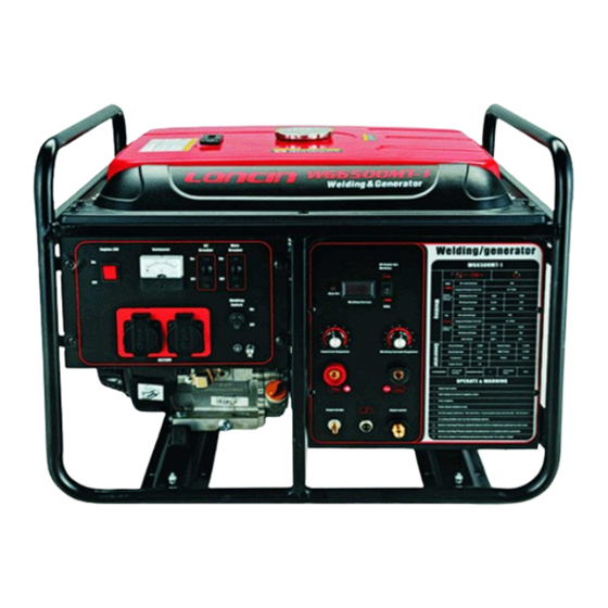
Description of the set’s parts and components and their functions III. Description of the set’s parts and components and their functions Fuel switch Fuel tank guard Throttle lever Welding chamber control cabinet Air filter Control panel Starter drain plug Fuel tank Frame Spark plug Carburetor... -
Page 12: Engine Switch
Description of the set’s parts and components and their functions 1) Engine switch Engine switch 2) Fuel switch The fuel switch is for opening and closing the passage of fuel flow from the fuel tank to the carburetor. If the fuel switch is not put in the ON position, the engine cannot run. When the engine is not to be used, the fuel switch must be put in the OFF position to prevent fuel leak. -
Page 13: Recoil Starter
Description of the set’s parts and components and their functions Throttle lever 4) Recoil starter Pulling the recoil starter grip enables the recoil starter to drive the engine’s crank shaft, which in turn starts the engine. Don’t let the starter grip spring back abruptly after starting; the starter grip should be let back gently. - Page 14 Description of the set’s parts and components and their functions 1—AC voltage meter 2—Engine switch 3—Main circuit breaker 4—Generator circuit breaker 5—Welding switch 6—Receptacle 7—Earthing terminal - 10 -...
-
Page 15: Preoperation Check
Preoperation check IV. Preoperation check 1) Routine check Observe whether there is any leak of engine oil or fuel. Observe whether there is any trace of damage. Check the positions of all guards and covers, and tightness of all bolts, nuts and screws. -
Page 16: Air Filter Check
Preoperation check Use unleaded gasoline with an octane rating of 90 or higher. Unleaded gasoline produces fewer engine and spark plug deposits and extends exhaust system life. Never use stale or contaminated gasoline or an oil/gasoline mixture. Avoid getting dirt or water in the fuel tank. 4) Air filter check Remove the air filter cover and inspect the filter. -
Page 17: Operation And Use Of The Set
Operation and use of the set V. Operation and use of the set 1) Starting the engine ① Remove all loads from the output end. ② Open fuel switch ③ Put AC circuit breaker in the OFF position. ④ Put throttle lever in the OFF position. Do not shut off the choke if the engine is started when it is warm. - Page 18 Operation and use of the set Before starting the generator, it should be confirmed that the total of all loads’ ② power values doesn’t exceed the generator’s rated power. Overload use will significantly shorten the generator’s service life. If the generator is be connected to multiple loads or electricity consumers, please remember to first connect the one with the highest starting current, then the one with the second highest starting current...
-
Page 19: Use Of Welding Power Supply
Operation and use of the set 450 ~ ●Motor 300VA Refrigerator X3 ~ 5 X2 750VA driven device Refrigerator 150W Electric fan 3) Use of welding power supply ①Description of welding chamber panel’s functions Display of preset current values Welding mode Overheating selection switch... -
Page 20: Stopping The Engine
Operation and use of the set Gas meter Torches Welding cable+ Work piece tank Welding cable- Connection of argon-arc welding ③Turn on the power switch of welding power supply Wait for about 2 to 3 minutes after turning on the power switch and the no-load voltage has been generated, then you may start welding operation. -
Page 21: Maintenance Of The Set
Every two years (2) Maintain more frequently when the generator is used in dusty areas. These items should be maintained by an authorized dealer of Loncin. If the generator is to be used frequently, maintenance shall be performed as per the schedule above to ensure long-time normal operation. -
Page 22: Engine Oil Change
Maintenance of the set Improper maintenance, or failure to correct a problem before operation, can cause a malfunction by which you can be hurt or killed. Always follow the recommended inspection and maintenance and schedules in this owner’s manual. 1) Engine oil change Drain the engine oil while the engine has been Upper limit Warmed to ensure complete and rapid draining. -
Page 23: Cleaning Fuel Sediment Cup
Maintenance of the set nonflammable detergent, or a high flash point detergent; squeeze the element to thoroughly remove the fluid in it. If the paper element is dirty, gently knock it several times; then use compressed air (with a pressure not higher than 207KPa) to blow it from the inside to the outside. Never use a brush to clean the paper element, or the air pores of the element will be clogged. -
Page 24: Spark Plug Check
Maintenance of the set 4) Spark plug check Recommended spark plugs: F7RTC and F7TC Remove the spark plug cap. ① ② Clean any dirt from around the spark plug base. Use the spark plug socket wrench to remove ③ the spark plug. ④... -
Page 25: Storage
Storage VII. Storage Contact with a hot engine part can cause a fire. Let the engine cool before transporting or storing the generator. If the generator is to be stored for a long period, the storage area must be kept clean and dry. -
Page 26: Troubleshooting
Troubleshooting VIII. Troubleshooting 1)Engine doesn’t start Is there fuel in the Refill the fuel tank? tank Is there enough engine recommended oil. oil in the crankcase? Still no spark plug Replace Contact spark generate normal sparks? spark plug authorized service station Check and clean Is there fuel in the... -
Page 27: Solving Common Problems Of Welding Power Supply
Troubleshooting 3) Solving common problems of welding power supply Only the persons with relevant qualifications can open the welding power supply to inspect, maintain and repair it. Phenomenon Possible cause Correction ○Incorrect operation ○Operate as per the manual ○Loose connector of the circuit board ○Restore god connection ○Visually observed... -
Page 28: Technical Parameters
Generator Rate output current ( A ) 21.7 Frequency ( Hz ) Power factor Cooling method Forced air cooling WG6500M-1 90/725 × 583 × 562 Weight(net) ( Kg ) Whole WG6500MT-1 100/725 × 583 × 562 /size ( mm )... -
Page 29: Schematic Diagram
Schematic diagram X. Schematic diagram - 25 -... -
Page 30: Ⅺ. Wheel And Handle Set(In Optional)
Wheel and handle Set(In Optional) Ⅺ. Wheel and handle Set(In Optional) 1 ) Assemble the 2 wheels on the axle with washer and lock nut. 2 ) Install the wheel kits on the frame mounting board with bolts and nuts. 3 )...
Need help?
Do you have a question about the WG6500M-1 and is the answer not in the manual?
Questions and answers