Table of Contents
Advertisement
Quick Links
Advertisement
Table of Contents

Subscribe to Our Youtube Channel
Related Manuals for LONCIN LC2000i


Summary of Contents for LONCIN LC2000i
- Page 1 LC2000i Service Manual LONCIN MOTOR CO., LTD.
- Page 2 SAFETY PRECAUTIONS • Static electric sparks caused by fuel flowing Thoroughly read this MANUAL before through a service station’s pump nozzle can operating the generator set. Safe operation ignite gasoline. Never fuel the generator set and top performance can only be attained with a service station’s pump nozzle.
- Page 3 SAFETY PRECAUTIONS • • Make sure that fasteners and clamps on the Benzene and lead may be found in gasoline generator set are tight. Keep guards in and have been identified by some states and position over fans, rotors, etc. federal agencies as causing cancer or reproductive toxicity.
-
Page 4: Table Of Contents
TABLE OF CONTENTS SECTION 1 INTRODUCTION 1-1 Generator Components .............. 1 1-2 Parameters ................ 2 SECTION 2 MAINTENANCE STANDARD 2-1 Engine Maintenance Standard ............3 2-2 Generator Maintenance Standard............4 2-3 Fastener Torque Specification ............4 2-4 Standard Fastener Torque Specification ..........4 SECTION 3 MAINTENANCE 3-1 Maintenance Schedule ............... - Page 5 TABLE OF CONTENTS 4-4-2 Cylinder Head / Valves ............27 4-4-3 Flywheel / Ignition Coil/Recoil Starter ..........33 4-4-4 Carburetor ..............37 4-5 Generator ................. 40 4-5-1 Fuel Tank ..............40 4-5-2 Muffler ................ 41 4-5-3 Frame/Bedplate Combination ............. 43 4-5-4 Motor .................
-
Page 6: Section 1 Introduction
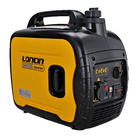
SECTION 1. INTRODUCTION 1-1 Generator Components FUEL TANK CAP FUEL TANK MUFFLER LEFT CARRYING HANDLE LEFT COVER RECOIL CONTROL STARTER GRIP PANEL RECOIL STARTER SPARK PLUG MUFFLER CARBURETOR RIGHT FUEL COCK CARRYING HANDLE AIR CLEANER MOTOR DIPSTICK LOUVER RIGHT COVER - 1 -... -
Page 7: Parameters
SECTION 1. INTRODUCTION 1-2 Parameters Model No. LC2000i Inverter Type Frequency /Hz 50/60 Rated Voltage /V 230/120 Max. output power / Rated output power /k Power factor Generator AC output quality ISO8528 G2 ≤5 Noise Level Acoustical 87.5 Power(3/4 load) -
Page 8: Section 2 Maintenance Standard
SECTION 2 MAINTENANCE STANDARD 2-1 Engine Maintenance Standard Part Item Standard Allowable limit 5000rpm Gasoline Max no-load speed 6000 rpm ≧1.17Mpa(1400rpm) Cylinder compression engine Cylinder Cylinder I.D. 48.6mm 48.765mm Cylinder Warpage 0.10mm head Skirt O.D. 48.585mm 48.445mm Piston-to-cylinder 0.03-0.05mm 0.12mm clearance Piston Piston pin bore I.D. -
Page 9: Generator Maintenance Standard
SECTION 2 MAINTENANCE STANDARD Table of resistance values of windings rated 230 V 2KW: Part Wire color Resistance Main winding Brown 4.11-4.55Ω Secondary winding Orange 0.38-0.42Ω DC winding Blue 0.19-0.21Ω Table of resistance values between windings rated 120V 2KW: Part Wire color Resistance Main winding... -
Page 10: Section 3 Maintenance
Every 2 years (2) (1) Service more frequently when it is used in dusty environments. (2) These items must be performed by a dealer franchised by Loncin (3) When the set is used frequently, the correct maintenance intervals above must be followed to ensure long-time use. -
Page 11: Engine Oil
SECTION 3. MAINTENANCE Install the cover and tighten the screws. 3-2 Engine Oil Note: Before each time of use, the generator must NOTE: Drain the oil while the engine is still be placed on a horizontal surface and check the oil warm to assure rapid and complete draining. -
Page 12: Air Cleaner
SECTION 3. MAINTENANCE 3-3 Air Cleaner A dirty air cleaner will restrict air flow to the carburetor, causing a lower engine power. Service air cleaner more frequently when operating the generator in extremely dusty areas. Using gasoline or flammable solvent to clean the filter element can cause a fire or explosion. -
Page 13: Fuel Sediment Cup Cleaning
SECTION 3. MAINTENANCE 3-4 Fuel Sediment Cup Cleaning After reassembly, check for leaks, The fuel sediment cup prevents dirt or water and make sure the work area is dry before which may be in the fuel tank from entering the starting the engine. -
Page 14: Spark Plug
SECTION 3. MAINTENANCE W16FP / W16FPR (DENSO) 3-6 Spark Plug W6BC / WR6BC (BOSCH) A spark plug of a wrong model or If the machine needs EMC Certification, engine wrong heat range may deteriorate the must use E6RTC spark plug engine’s performance or even damage the If the electrode is damaged, or insulation is engine. -
Page 15: Valve Clearance
SECTION 3. MAINTENANCE d) Recheck valve clearance after tightening 3-7 Valve Clearance the lock nut. Valve clearance inspection and adjustment must be performed with the engine cold. Remove the cylinder head cover, and pull the starter grip (until a resistance is clearly felt) to set the piston at top dead center of the FEELER GAUGE compression stroke (both valves fully closed). -
Page 16: Troubleshooting
SECTION 4. DISASSEMBLY AND SERVICE ENGINE FLOODED to much fuel 4-1 Troubleshooting ( TRY AGAIN AFTER A FEW MINUTES ) 4-1-1 Hard Starting FUEL LEVEL too low ( ADD FUEL INTO FUEL TANK ) FUEL SYSTEM FUEL FILTER clogged (SEE 3-4) CARBURETOR out of adjustment (SEE 4-4-4) AIR FILTER dirty... -
Page 17: Low Power
SECTION 4. DISASSEMBLY AND SERVICE 4-1-2 Low Power FUEL QUALITY poor (ADD CLEAN FRESH FUEL OF DESIGNATED QUALITY INTO TANK) FUEL FILTER clogged (SEE 3-4) FUEL SYSTEM CARBURETOR out of adjustment (SEE 4-4-4) CHOKE LEVER not fully open (MOVE TO “RUN” POSITION) AIR FILTER dirty (SEE 3-3) SPARK PLUG faulty... -
Page 18: Speed Unstable
SECTION 4. DISASSEMBLY AND SERVICE 4-1-3 Speed Unstable FUEL low / poor quality / contaminated ADD CLEAN FRESH FUEL OF DESIGNATED QUALITY INTO TANK FUEL FILTER clogged FUEL SYSTEM (SEE 3-4) CARBURETOR clogged (SEE 4-4-4) VALVE CLEARANCE incorrect (SEE 3-7) SPEED COMPRESSION VALVE SEAT worn and leak... -
Page 19: Low Speed/Voltage
SECTION 4. DISASSEMBLY AND SERVICE 4-1-4 Low Speed / Voltage AIR FILTER dirty (SEE 3-3) FUEL QUALITY poor / contaminated ADD CLEAN FRESH FUEL OF DESIGNATED FUEL SYSTEM QUALITY INTO TANK CARBURETOR has water (SEE 4-4-4) CHOKE LEVER not fully open (MOVE TO “RUN”... -
Page 20: Exhaust Color Abnormal
SECTION 4. DISASSEMBLY AND SERVICE 4-1-5 Exhaust Color Abnormal AIR CLEANER dirty (SEE 3-3) BLACK CARBURETOR faulty (SEE 4-4-4) LOAD excessive (REMOVE EXTRA LOAD) ENGINE temperature too low EXHAUST (WHEN STARTING NORMALLY) COLOR WHITE ABNORMAL FUEL QUALITY poor/ contaminated ADD CLEAN FRESH FUEL OF DESIGNATED QUALITY INTO TANK QUALITY poor/ FUEL... -
Page 21: No Ac Output Voltage
SECTION 4. DISASSEMBLY AND SERVICE 4-1-6 No AC Output Voltage OUTPUT RECEPTACLE faulty (CHECK FOR BURN, IF SO, REPLACE IT) ENGINE SPEED abnormal (CHECK IT AND ADJUST) NO AC OUTPUT VOLTAGE STATOR WINDING COIL defective (SEE 4-5-4) INVERTER faulty (SEE 4-5-5) 4-1-7 No DC Output Voltage RECTIFIER BRIDGE CONNECTION loose or faulty... -
Page 22: Preparing To Service
SECTION 4. DISASSEMBLY AND SERVICE 4-2 Preparing to Service 4-2-1 Safety Precautions TABLE 4-1 HAZARDS AND THEIR SOURCES • Leaking or spilled fuel There are hazards in servicing gensets. Study • Hydrogen gas from battery Safety precautions and become familiar with the Fire hazards listed in table 4-1. -
Page 23: Disassembly Chart
SECTION 4. DISASSEMBLY AND SERVICE 4-3 Disassembly Chart LEFT RIGHT CARRYING HANDLES CONTROL PANEL LOUVER PANEL BED FUEL TANK INVERTER FRAME BEDPLATE MOUNT RUBBER BRACKET STATOR ROTOR MAIN UNIT BUFFER MOTOR REAR SUPPOER MUFFLER ENGINE CARBURETOR FLYWHEEL FAN COVER RECOIL STARTER AIR CLEANER GENERATOR DISASSEMBLY This chart is a quick-reference guide for... -
Page 24: Engine
SECTION 4. DISASSEMBLY AND SERVICE PISTON 4-4 Engine 4-4-1 Camshaft / piston REASSEMBLY: Install with a.DISASSEMBLY/ REASSEMBLY triangle mark toward push CAMSHAFT rod hole. REASSEMBLY: Check that the decompressor weight moves smoothly, and VALVE the spring is not weak or worn. LIFTER Install with the timing marks BREATHER... - Page 25 SECTION 4. DISASSEMBLY AND SERVICE b.PISTON/ PISTON RING PISTON RING REASSEMBLY: 1) Install all rings with the markings facing upward. 2) Be sure that the top (chrome plated) and second rings are not interchanged. 3) Check that the rings rotate smoothly after installation. 4) Set the piston ring end gaps 120 degrees apart, and do not align the gaps with the piston pin bore.
- Page 26 SECTION 4. DISASSEMBLY AND SERVICE CRANKSHAFT c.CAMSHAFT/ CRANKSHAFT PUNCH CAMSHAFT MARKS While installing the camshaft, align the punch marks on the camshaft gear and timing gear (small gear on the crankshaft.) d. INSPECTION PISTON Check contact between piston and cylinder, defect of ring grooves, burn of piston top, cracks, etc. If the damage is severe, such as cracks, replace the piston.
- Page 27 SECTION 4. DISASSEMBLY AND SERVICE and groove’s upper or lower surface to measure the clearance. Standard Service limit 0.15 mm 0.015-0.045 mm 4) PISTON RING WIDTH Standard Service limit Top/Second 1.5 mm 1.37 mm 5) PISTON RING END GAP Standard Service limit Top/second 0.02-0.04 mm...
- Page 28 SECTION 4. DISASSEMBLY AND SERVICE 8) PISTON PIN-TO-PISTON PIN BORE CLEARANCE Use an inside micrometer and an outside micrometer to measure piston pin bore’s inside diameter and piston pin’s outside diameter, then use the measured values to calculate the difference; if difference is beyond service limit, replace piston or piston pin according to wear status.
- Page 29 SECTION 4. DISASSEMBLY AND SERVICE 3) CRANKPIN O.D. Standard Service limit 21.985 mm 21.925 mm 4) CONNECTING ROD BIG END SIDE CLEARANCE Standard Service limit 0. 1-0.7mm 1.1mm 5) CONNECTING ROD BIG END OIL CLEARANCE (RADIAL) 12N.m a) Clean all oil from crank pin surface. b) Place a piece of plastigauge, install connecting rod, and tighten the bolts to the specified torque.
- Page 30 SECTION 4. DISASSEMBLY AND SERVICE CAMSHAFT As the main driving piece of the gasoline engine’s valve actuating mechanism, the camshaft controls opening and closing of intake and exhaust valves following a regular rule. Check cam surface and cam height for damage, check whether camshaft and bearings have play or are worn, if so, replace all of them. 1) CAMSHAFT CAM HEIGHT Standard Service limit...
- Page 31 SECTION 4. DISASSEMBLY AND SERVICE PLAY PLAY BEARING Clean bearing in solvent and dry it. Spin the bearing by hand and check for play. replace the bearing if it is noisy or has excessive play AXIAL RADIAL OIL LEVEL SWITCH Measure continuity of oil level switch with an ohmmeter.
-
Page 32: Cylinder Head / Valves
SECTION 4. DISASSEMBLY AND SERVICE 4-4-2 Cylinder Head / Valves a. DISASSEMBLY/ REASSEMBLY BREATHER TUBE REMOVAL/ INSTALLATION: CYLINDER HEAD BOLT M6×50(4) Connect one end to cylinder head cover, the other end to REMOVAL/ INSTALLATION: breather chamber cap’s Loosen and tighten the bolts in a vertical-up vent. - Page 33 SECTION 4. DISASSEMBLY AND SERVICE b. DISASSEMBLY/ REASSEMBLY ROCKER SPARK PLUG PIVOT BOLT ROCKER ARM REASSEMBLY: REASSEMBLY: REASSEMBLY: Before installing, check Clean and adjust spark Before installing, check for for wear on the surface plug before reinstalling it wear surface where contacting the valve.
- Page 34 SECTION 4. DISASSEMBLY AND SERVICE c.INSPECTION 1) VALVE STEM O.D. Inspect each valve stem’s outer diameter, if it is less than standard value or beyond service limit, or valve face has visible burns or cracks, replace it with a new one. Standard Service limit 4.968 mm...
- Page 35 SECTION 4. DISASSEMBLY AND SERVICE measuring. Replace valve guides if their inner diameters are smaller than standard value or beyond service limit. VALVE GUIDE Standard Service limit REAMER 5.012 mm 5.072 mm Replace: a) Put replacement valve guides in a refrigerator’s freezing chamber to freeze it for about 1 hour.
- Page 36 SECTION 4. DISASSEMBLY AND SERVICE d) Check the valve stem-to-guide clearance. e) Valve stem-to-guide clearance: Deduct the valve stem VALVE GUIDE outside diameter from the valve guide bore’s inside diameter VALVE CLIP GUIDE to get the clearance between the valve guide and valve stem. DRIVER f) If the clearance is over the service limit, judge whether a if it...
- Page 37 SECTION 4. DISASSEMBLY AND SERVICE e) Make a light pass with the 45°cutter to remove any possible burrs at the edges of the seat. f)After resurfacing seats, inspect for even valve seating. width Apply colorant to the valve’s tapered face, insert the valve and press it forcefully several times, be sure the valve does not rotate on the seat.
-
Page 38: Flywheel / Ignition Coil/Recoil Starter
SECTION 4. DISASSEMBLY AND SERVICE 4-4-3 Flywheel / Ignition Coil/Recoil Starter a. DISASSEMBLY/ REASSEMBLY RECOIL STARTER ASSY FAN COVER REASSEMBLY: IGNITON COIL DISASSEMBLY/ REASSEMBLY: Remove earth grass Remove all dirt before installing. DISASSEMBLY/ REASSEMBLY: sticking to it , pay attention to Check for cracked or damaged installing direction insulation before installation , to... - Page 39 SECTION 4. DISASSEMBLY AND SERVICE b.INSPECTION CHARGE COIL, IGNITION COIL Attach one ohmmeter lead to charge coil’s black lead while touching the other tester to the iron core. Measured resistance value should be 0Ω . Attach one ohmmeter lead to charge coil’s red/white lead while touching the other tester to the iron core.
- Page 40 SECTION 4. DISASSEMBLY AND SERVICE c. DISASSEMBLY/ REASSEMBLY (STARTER ASSY) The recoil starter can cause personal injury, Wear safety glasses. Do not let the recoil spring snap out. HEXAGON SHOULDER BOLT REASSEMBLY: Apply thread locking STARTER ROE Friction RATCHET compound to thread spring REASSEMBLY: first.
- Page 41 SECTION 4. DISASSEMBLY AND SERVICE ASSEMBLY OF RECOIL STARTER STARTER CASE Wear glovers and safety glasses to protect your RETURN hands and eyes. SPRING Don’t let return spring snap out. 1) Put return spring into spring cover, hook spring’s outer hook firmly to the cover’s gap and align with starter reel’s STARTER REEL...
-
Page 42: Carburetor
SECTION 4. DISASSEMBLY AND SERVICE 4-4-4 Carburetor a. DISASSEMBLY/ REASSEMBLY STEP MOTOR BOLT M3×5(2) PROTECTIVE COVER Torque: (1~1.5) N•m SPEED-VARIABLE STEP MOTOR SCREW M5×12 (2) Torque: (5~7) N•m STEP MOTOR MOUNTING BRACKET CABLE CHOKE STAY HOLDER COMP. AIR CLEANER PACKING CARBURETOR CARBURETOR PACKING... - Page 43 SECTION 4. DISASSEMBLY AND SERVICE b.DISASSEMBLY/ REASSEMBLY Gasoline is flammable and explosive. Close the fuel shut off valve, and drain the carburetor before servicing the carburetor. Smoking and fire are prohibited. CHOKE ASSY THROTTLE ASSY CARBURETOR BODY REASSEMBLY: Clean internal passages orifices with...
- Page 44 SECTION 4. DISASSEMBLY AND SERVICE c.INSPECTION SPEED VARIABLE STEPPER MOTOR Measure resistance between ends of stepper motor socket 2’s diagonal, resistance value should be 50±1Ω,if it is exceeded, replace the stepper motor. Rotate stepper motor’s central shaft when the motor’s power is on, the shaft should not be stuck or has play, if so, replace the motor.
-
Page 45: Generator
SECTION 4. DISASSEMBLY AND SERVICE 4-5 Generator 4-5-1 Fuel Tank DISASSEMBLY/ REASSEMBLY Gasoline is flammable and explosive, drain carburetor fuel tube before disassembly, spilled fuel must be wiped off immediately. FUEL TANK CAP REASSEMBLY: FUEL FILLER RUBBER HOUSING Make sure that the air vent hole is clean and unclogged. -
Page 46: Muffler
SECTION 4. DISASSEMBLY AND SERVICE 4-5-2 Muffler DISASSEMBLY/ REASSEMBLY MUFFLER EXHAUST PIPE MUFFLER GASKET PROTECTOR COVER NUT M6(2) Torque: (8~12) N•m SPARK ARRESTER REASSEMBLY: Remove carbon deposits with a wire brush before installation. REASSEMBLY: Install after removing the carbon deposits from the muffler using a plastic hammer. - Page 47 SECTION 4. DISASSEMBLY AND SERVICE THERMAL INSULATION ALUMINUM SHEET WIND MUFFLER THERMAL INSULATION DIVERSION PROTECTOR ALUMINUM SHEET COVER COVER (REAR) SHROUD CLIP NUT M6×14 (2) Torque: (8~12)N•m MUFFLER SELF TAPPING PROTECTOR SCREW ST4×15 (5) COVER RUBBER STRIP REASSEMBLY: I-SHAPE RUBBER Clamp muffler protector RING cover’s rubber strip onto...
-
Page 48: Frame/Bedplate Combination
SECTION 4. DISASSEMBLY AND SERVICE 4-5-3 Frame/Bedplate Combination DISASSEMBLY/ REASSEMBLY MAIN UNIT BUFFER MOUNT (4) REASSEMBLY: Align with frame/bedplate CUSHING RUBBER combination’s installation hole install it. REASSEMBLY: Make sure the rubber is not chapped, hardened, or worn. Install it under the engine, make Pay attention to installing direction. -
Page 49: Motor
SECTION 4. DISASSEMBLY AND SERVICE 4-5-4 Motor a. DISASSEMBLY/ REASSEMBLY MOTOR ROTOR REASSEMBLY: Wipe off dirt and oil from crankcase and rotor’s tapered part, then install. END CAP NUT M12×1.25 Torque: (60~70)N•m ENGINE REASSEMBLY: Put main winding’s output lead on the engine’s Bottom, then put the engine on the bedplate’s rubber shock absorbers. - Page 50 SECTION 4. DISASSEMBLY AND SERVICE MOTOR STATOR REASSEMBLY: BOLT M6×30 (5) Put stator’s wires through rear Torque: (8~12)N•m housing’s hole, and position them on the rear housing’s mounting holes. BOLT M6×30 (2) Torque: (8~12)N•m MOTOR REAR HOUSING BOLT M6×12 (2) Torque: (8~12)N•m NUT M12×1.25 Torque: (60~70)N•m...
- Page 51 SECTION 4. DISASSEMBLY AND SERVICE Table of resistance between windings rated 120V b. INSPECTION Wire Resistance color Main winding Brown 1.18-1.30Ω Secondary Orange 0.38-0.42Ω winding DC winding Blue 0.19-0.21Ω If resistance is zero or infinite, replace the stator. Remove the stator from the motor. Check whether insulation of stator windings’enameled wires and leads’...
-
Page 52: Inverter
SECTION 4. DISASSEMBLY AND SERVICE 4-5-5 Inverter a. DISASSEMBLY/ REASSEMBLY FUEL TANK CHOKE CABLE RUBBER CUSHION INVERTER INSTALLATION RECTIFIER BRACKET BRIDGE COMBINATION SWITCH INVERTER INCHING SWITCH BOLT M6×14 (6) Torque: (8~12)N•m - 47 -... - Page 53 SECTION 4. DISASSEMBLY AND SERVICE loading). Use the ohmmeter scale to measure 3-phase Inverter connectors (measure resistance between each two of them), if the measured resistance value is zero or Check whether colors of inverter’s leads have infinite, replace the inverter. changed, whether inverter’s packing resin has bulging blisters, check whether all the inverter’s electric parts, connectors, and connecting wires have visible color...
- Page 54 SECTION 4. DISASSEMBLY AND SERVICE With spring leaves compressed firmly, use Note 1: “Continuity” refers to the diode’s on state characteristic, it is different from short ohmmeter scale to measure resistance between circuiting. When inspection result of any two output terminals. If measured resistance value section fails, replace with a new rectifier bridge.
-
Page 55: Control Panel
SECTION 4. DISASSEMBLY AND SERVICE 4-5-6 Control Panel OIL WARNING LIGHT WIRE HARNESS ASSY AC OUTPUT CONTROL INDICATOR PANEL OVERLOAD LIGHT IDLE SWITCH RECEPTACLE PANEL BED RECEPTACL WATERP GRID-CONNECTED ROOF RECEPTACLE a. DISASSEMBLY/ REASSEMBLY When combination switch is in “OFF” postion, ingnition circuit is close, which means INSPECTION inching switch’s two output terminals are made,... - Page 56 SECTION 4. DISASSEMBLY AND SERVICE alert system will automatically shut the engine, and Wire harness oil warning light goes on; the engine cannot be started until oil is added to reach the required level. Note: If the engine stalls or cannot be started, turn power switch into “ON”...
- Page 57 SECTION 4. DISASSEMBLY AND SERVICE engine. DC breaker protector 2. Lower total power of all connected electrical equipment into the range of rated output. 3. Check cooling air intake port for obstruction by foreign matters, and whether relevant control parts are abnormal, if so, solve the problem immediately.
- Page 58 SECTION 4. DISASSEMBLY AND SERVICE energy-saving equipment controls engine speed according to the load connected, lowering fuel consumption rate and noise. Use an ohmmeter to check the switch’s output leads, they should have continuity. ② “OFF” When power down switch is in “OFF” position, whether the load is connected or not, the engine will run at rated speed (5000r/min).
-
Page 59: Outer Case Assembly
SECTION 4. DISASSEMBLY AND SERVICE 4-5-7 Outer case assembly a. DISASSEMBLY/ REASSEMBLY ROPE GRIP LOUVER HOLE LEFT CARRYING SCREW M5×12 LEFT COVER HANDLE DECORATION SPARK PLUG MAINTENANCE SCREW M5×12 OPENING CAP RUBBER DAMPER (2) CLIP NUT (3) BOLT M6×16 (3) Torque: (8~12)N•m CLIP NUT (3) CLIP... -
Page 60: Section 5 Wiring Diagrams
SECTION 5 WIRING DIAGRAMS 5-1 LC2000i Wiring diagram 60Hz,120V without grid-connected receptacle INVERTER BLOCK GENERATOR BLOCK CONTROL PANEL BLOKC 变频器 电机 面板 AC receptacle 交流插座 Hoofdspoel inverter ESC switch 主电线圈 变频器 节能开关 AC pilot light 交流输出指示灯 Subspoel 子线圈 overload indicator light 过载指示灯... - Page 61 SECTION 5 WIRING DIAGRAMS 60Hz,120V with a grid-connected receptacle INVERTER BLOCK GENERATOR BLOCK CONTROL PANEL BLOKC 变频器 电机 面板 AC receptacle 交流插座 parallel receptacle 并网插座 并网插座 Hoofdspoel inverter ESC switch 主电线圈 变频器 节能开关 AC pilot light 交流输出指示灯 Subspoel 子线圈 overload indicator light 过载指示灯...
- Page 62 SECTION 5 WIRING DIAGRAMS 50Hz,230V without grid-connected receptacle INVERTER BLOCK GENERATOR BLOCK CONTROL PANEL BLOKC 变频器 电机 面板 AC receptacle 交流插座 Hoofdspoel inverter ESC switch 主电线圈 变频器 节能开关 AC pilot light 交流输出指示灯 Subspoel 子线圈 overload indicator light 过载指示灯 circuit breaker 10A DC-spoel 直流线圈...
- Page 63 SECTION 5 WIRING DIAGRAMS 50Hz,230V with a grid-connected receptacle INVERTER BLOCK GENERATOR BLOCK CONTROL PANEL BLOKC 变频器 电机 面板 AC receptacle 交流插座 parallel receptacle 并网插座 Hoofdspoel inverter ESC switch 主电线圈 变频器 节能开关 AC pilot light 交流输出指示灯 Subspoel 子线圈 overload indicator light 过载指示灯...
Need help?
Do you have a question about the LC2000i and is the answer not in the manual?
Questions and answers