Table of Contents
Advertisement
Advertisement
Table of Contents

Related Manuals for LONCIN LC3000i


Summary of Contents for LONCIN LC3000i
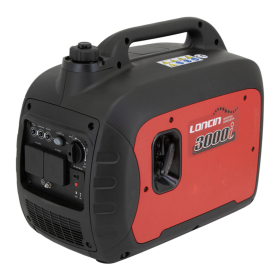
- Page 1 LC3000i Service Manual LONCIN MOTOR CO., LTD.
- Page 2 SAFETY PRECAUTIONS • Thoroughly read the OPERATOR’S MANUAL Static electric sparks caused by fuel flowing before operating the generator set. Safe through a service station pump nozzle can operation and top performance can only be ignite gasoline. Never fill the generator set attained when equipment is operated and with a service station pump nozzle.
- Page 3 SAFETY PRECAUTIONS • Battery Gases are explosive Benzene and lead may be found in gasoline • and have been identified by some state and Wear safety glasses when servicing federal agencies as causing cancer or batteries. reproductive toxicity. Do not ingest, inhale or •...
-
Page 4: Table Of Contents
TABLE OF CONTENTS SECTION 1 INTRODUCTION 1-1 Generator Components .............. 1 1-2 Parameters ................ 2 SECTION 2 MAINTENANCE STANDARD 2-1 Engine Maintenance Standard ............3 2-2 Generator Maintenance Standard............4 2-3 Fastener Torque Specification ............4 2-4 Standard Fastener Torque Specification ..........5 SECTION 3 MAINTENANCE 3-1 Maintenance Schedule ............... - Page 5 TABLE OF CONTENTS 4-4-2 Cylinder Head / Valves ............29 4-4-3 Generator / Ignition Coil/Recoil Starter ..........35 4-4-4 Carburetor ..............40 4-5 Generator ................. 43 4-5-1 Fuel Tank ..............43 4-5-2 Muffler ................ 44 4-5-3 Frame/Bedplate Combination ............. 43 4-5-4 Inverter ...............
-
Page 6: Section 1 Introduction
SECTION 1. INTRODUCTION 1-1 Generator Components FUEL TANK CAP RECOIL STARTER OILING PORT RUBBER SLEEVE CONTROL PANEL RIGHT APPEARANCE COVER PLATE PANEL BED BOTTOM PLATE FRAME SPARK PLUG COVER LOUVER MUFFLER OIL OBSERVATION WINDOWS - 1 -... -
Page 7: Parameters
SECTION 1. INTRODUCTION 1-2 Parameters Model No. LC3000i Inverter Type Frequency /Hz 50/60/ 50&60 Rated Voltage /V 100/110/120/230 Max. output power / Rated output power /k Power factor Generator AC output quality ISO8528 G2 ≤5 Noise Level dB/LpA/LwA/K 64.7 4m (3/4 load) DC Output 12-8.3... -
Page 8: Section 2 Maintenance Standard
SECTION 2 MAINTENANCE STANDARD 2-1 Engine Maintenance Standard Unspecified unit:mm LC165F-4 Part Item Standard Service limit - Engine Maximum speed 3850±150rpm Cylinder Cylinder bore 65.0 65.165 64.985 64.845 Skirt O.D. Piston-to-cylinder clearance 0.015-0.05 0.12 Piston Piston pin bore ID 13.002 13.048 Piston pin-to-piston pin bore 0.002-0.014... -
Page 9: Generator Maintenance Standard
SECTION 2 MAINTENANCE STANDARD - Resistance Secondary coil 5.9-7.1Ω - Air gap (at flywheel) 0.3-0.4 2-2 Generator Maintenance Standard Table of resistance values of windings rated 230 V 2.3KW: Part Wire color Resistance 3.06Ω±15% Main winding Brown 0.42Ω±15% Power supply winding Orange 0.086Ω±15% DC winding... -
Page 10: Standard Fastener Torque Specification
SECTION 2 MAINTENANCE STANDARD 2-4 Standard Fastener Torque Specification Torque range (N.m) Faster Thread specification 5mm bolt, nut 6mm bolt, nut 8-12 Bolt, nut 8mm bolt, nut 20-28 10mm bolt, nut 35-40 12mm bolt, nut 50-60 - 5 -... -
Page 11: Section 3 Maintenance
SECTION 3 MAINTENANCE 3-1 Maintenance Schedule Accidental starting of the generator Good maintenance is essential to safe, set during maintenance can cause severe economical and zero-failure operation, and is also personal injury or death. Before performing good for environment protection. Under hot or dusty maintenance, disconnect the spark plug wire operating conditions some maintenance operations from the spark plug. - Page 12 SECTION 3 MAINTENANCE if necessary Valve Check and adjust ★ clearance when engine is cold Check all fittings Fittings/ ★ and fasteners. fasteners Correct if necessary. The point where abnormality ○ was recognized by use (1) Initial replacement of the engine oil is after before one month or after 20 hours of operation. (2) The air filter needs to be cleaned more frequently when using in unusually wet or dusty areas.
-
Page 13: Engine Oil
SECTION 3. MAINTENANCE 3-2 Engine Oil Note: Before each time of use, the generator must NOTE: Drain the oil while the engine is still be placed on a horizontal surface and check the oil warm to assure rapid and complete draining. level after stopping the engine. -
Page 14: Air Cleaner
SECTION 3. MAINTENANCE 3-3 Air Cleaner A dirty air cleaner will restrict air flow to the carburetor, causing a lower engine power. Service air cleaner more frequently when operating the generator in extremely dusty areas. Using gasoline or flammable solvent to clean the filter element can cause a fire or explosion. -
Page 15: Clean Fuel Filter
SECTION 3. MAINTENANCE 3-4 Clean fuel filter After reassembly, check for leaks, and make sure the work area is dry before The fuel filte prevents dirt or water which may starting the engine. be in the fuel tank from entering the carburetor. If the generator has not been run for a long time, the fuel filte should be cleaned. -
Page 16: Spark Plug
SECTION 3. MAINTENANCE 3) Check for discoloration and remove any carbon deposits. The porcelain insulator around the center 3-6 Spark Plug electrode of spark plug should be a medium to light tan color. A spark plug of a wrong model or wrong heat range may deteriorate the 4) Check the spark plug type and gap engine’s performance or even damage the... -
Page 17: Valve Clearance
SECTION 3. MAINTENANCE 5)Install the spark plug If installing a new spark plug, tighten l/2 turn after 3) If adjustment is necessary, proceed as follows: the spark plug has firmly pressed on the washer. If a) Use a clamp to hold the rocker arm pivot and use a wrench to loosen the pivot lock reinstalling a used spark plug, tighten l/8 - l/4 turn nut. -
Page 18: Troubleshooting
SECTION 4. DISASSEMBLY AND SERVICE 4-1 Troubleshooting ENGINE FLOODED to much fuel 4-1-1 Hard Starting ( TRY AGAIN AFTER A FEW MINUTES ) FUEL LEVEL too low ( ADD FUEL INTO FUEL TANK ) FUEL SYSTEM FUEL FILTER clogged (SEE 3-4) CARBURETOR out of adjustment (SEE 4-4-4) AIR FILTER dirty... -
Page 19: Low Power
SECTION 4. DISASSEMBLY AND SERVICE 4-1-2 Low Power FUEL QUALITY poor (ADD CLEAN FRESH FUEL OF DESIGNATED QUALITY INTO TANK) FUEL FILTER clogged (SEE 3-4) FUEL SYSTEM CARBURETOR out of adjustment (SEE 4-4-4) CHOKE LEVER not fully open (MOVE TO “RUN” POSITION) AIR FILTER dirty (SEE 3-3) SPARK PLUG faulty... -
Page 20: Speed Unstable
SECTION 4. DISASSEMBLY AND SERVICE 4-1-3 Speed Unstable FUEL low / poor quality / contaminated ADD CLEAN FRESH FUEL OF DESIGNATED QUALITY INTO TANK FUEL SYSTEM FUEL FILTER clogged (SEE 3-4) CARBURETOR clogged (SEE 4-4-4) VALVE CLEARANCE incorrect (SEE 3-7) SPEED COMPRESSION VALVE SEAT worn and leak... -
Page 21: Low Speed/Voltage
SECTION 4. DISASSEMBLY AND SERVICE 4-1-4 Low Speed / Voltage AIR FILTER dirty (SEE 3-3) FUEL QUALITY poor / contaminated ADD CLEAN FRESH FUEL OF DESIGNATED FUEL SYSTEM QUALITY INTO TANK CARBURETOR has water (SEE 4-4-4) CHOKE LEVER not fully open (MOVE TO “RUN”... -
Page 22: Exhaust Color Abnormal
SECTION 4. DISASSEMBLY AND SERVICE 4-1-5 Exhaust Color Abnormal AIR CLEANER dirty (SEE 3-3) BLACK CARBURETOR faulty (SEE 4-4-4) LOAD excessive (REMOVE EXTRA LOAD) ENGINE temperature too low EXHAUST (WHEN STARTING NORMALLY) COLOR WHITE ABNORMAL QUALITY poor/ FUEL contaminated ADD CLEAN FRESH FUEL OF DESIGNATED QUALITY INTO TANK QUALITY poor/ FUEL... -
Page 23: No Ac Output Voltage
SECTION 4. DISASSEMBLY AND SERVICE 4-1-6 No AC Output Voltage OUTPUT RECEPTACLE faulty (CHECK FOR BURN, IF SO, REPLACE IT) ENGINE SPEED abnormal (CHECK IT AND ADJUST) NO AC OUTPUT VOLTAGE STATOR WINDING COIL defective (SEE 4-4-3) INVERTER faulty (SEE 4-5-4) 4-1-7 No DC Output Voltage RECTIFIER BRIDGE CONNECTION loose or faulty... -
Page 24: Preparing To Service
SECTION 4. DISASSEMBLY AND SERVICE 4-2 Preparing to Service 4-2-1 Safety Precautions TABLE 4-1 HAZARDS AND THEIR SOURCES • Leaking or spilled fuel There are hazards in servicing gensets. Study • Hydrogen gas from battery Safety precautions and become familiar with the Fire hazards listed in table 4-1. -
Page 25: Disassembly Chart
SECTION 4. DISASSEMBLY AND SERVICE 4-3 Disassembly Chart LEFT RIGHT CARRYING HANDLES CONTROL PANEL LOUVER PANEL BED FUEL TANK INVERTER FRAME BEDPLATE MOUNT RUBBER BRACKET STATOR ROTOR MAIN UNIT BUFFER MOTOR REAR SUPPOER MUFFLER ENGINE CARBURETOR FLYWHEEL FAN COVER RECOIL STARTER AIR CLEANER GENERATOR DISASSEMBLY This chart is a quick-reference guide for... -
Page 26: Engine
SECTION 4. DISASSEMBLY AND SERVICE 4-4 Engine 4-4-1 Crankcase /Camshaft / piston a.DISASSEMBLY/ REASSEMBLY PISTON REASSEMBLY: CONNECTING ROD Install with triangle mark REASSEMBLY: toward push Install with the oil dipper toward BOLT M8×32 rod hole. the governor arm’s hole end and Torque: (26~32) N•m ribs connecting rod must be aligned. - Page 27 SECTION 4. DISASSEMBLY AND SERVICE b.PISTON/ PISTON RING PISTON RING REASSEMBLY: 1) Install all rings with the markings facing upward. 2) Be sure that the top (chrome plated) and second rings are not interchanged. 3) Check that the rings rotate smoothly after installation. 4) Set the piston ring end gaps 150°...
- Page 28 SECTION 4. DISASSEMBLY AND SERVICE CRANKSHAFT CAMSHAFT c.CAMSHAFT/ CRANKSHAFT PUNCH MARKS While installing the camshaft, align the punch marks on the camshaft gear and timing gear (small gear on the crankshaft.) d. INSPECTION PISTON Check contact between piston and cylinder, defect of ring grooves, burn of piston top, cracks, etc. If the damage is severe, such as cracks, replace the piston.
- Page 29 SECTION 4. DISASSEMBLY AND SERVICE insert the feeler gauge into clearance between each ring and groove’s upper or lower surface to measure the clearance. Standard Service limit 0.15 mm 0.015-0.045 mm 4) PISTON RING HEIGHT Standard Service limit Top/Second 1.0 mm 0.9 mm Oil ring 2.5 mm...
- Page 30 SECTION 4. DISASSEMBLY AND SERVICE 7) PISTON PIN O.D. Standard Service limit 13.0 mm 12.954 mm 8) PISTON PIN BORE I.D. Standard Service limit 13.002 mm 13.048 mm 9) PISTON PIN-TO-PISTON PIN BORE CLEARANCE Use an inside micrometer and an outside micrometer to measure piston pin bore’s inside diameter and piston pin’s outside diameter, then use the measured values to calculate the difference;...
- Page 31 SECTION 4. DISASSEMBLY AND SERVICE CONNECTING ROD If the connecting rod is bent or twisted, or its big end’s bearing bush and small end shaft housing’s outer ring has play, or one of its sides has cracks, the connecting rod must be scrapped and replaced with a new one. 1) CONNECTING ROD SMALL END I.D.
- Page 32 SECTION 4. DISASSEMBLY AND SERVICE 5) CONNECTING ROD BIG END OIL CLEARANCE (RADIAL) 12-14 N.m a) Clean all oil from crank pin surface. b) Place a piece of plastigauge, install connecting rod, and tighten the bolts to the specified torque. Tightening torque: 12-14N.m Note: Do not rotate crankshaft when tightening the bolts.
- Page 33 SECTION 4. DISASSEMBLY AND SERVICE 2) CAMSHAFT DIAMETER Standard Service limit 13.984 mm 13.916 mm 3) CAMSHAFT HOLDER ID Standard Service limit 14.0 mm 14.048 mm PLAY PLAY BEARING Clean bearing in solvent and dry it. Spin the bearing by hand and check for play. replace the bearing if it is noisy or has excessive play AXIAL RADIAL...
-
Page 34: Cylinder Head / Valves
SECTION 4. DISASSEMBLY AND SERVICE 4-4-2 Cylinder Head / Valves a. DISASSEMBLY/ REASSEMBLY FILTER SCREEN CYLINDER HEAD COVER BREATHER TUBE Assembly: dirty ones are required to REMOVAL/ INSTALLATION: be cleaned timely. Connect one end to cylinder head cover, the other end to breather chamber cap’s... - Page 35 SECTION 4. DISASSEMBLY AND SERVICE b. DISASSEMBLY/ REASSEMBLY EXHAUST VALVE Reassembly: INTAKE VALVE Check exhaust valve taper face Reassembly: chipping or excessive Don’t interchange carbon deposits exhaust before assembling. intake valves. VALVE SPRING RETAINER VALVE LIFTER LOCKER VALVE SHAFT, ROCKER ARM CYLINDER HEAD SEAL,GUIDE PUSH ROD (2)
- Page 36 SECTION 4. DISASSEMBLY AND SERVICE c.INSPECTION 1) VALVE STEM O.D. Inspect each valve stem’s outer diameter, if it is less than standard value or beyond service limit, or valve face has visible burns or cracks, replace it with a new one. Standard Service limit 5.48 mm...
- Page 37 SECTION 4. DISASSEMBLY AND SERVICE b) Ream the valve guides to remove any carbon deposits before measuring. Replace valve guides if their inner diameters are smaller than standard value or beyond service limit. VALVE GUIDE REAMER Standard Service limit 5.50 mm 5.572 mm Replace: a) Put replacement valve guides in a refrigerator’s freezing...
- Page 38 SECTION 4. DISASSEMBLY AND SERVICE during installation. Replace the valve guide if it is bent or damaged. d) Check the valve stem-to-guide clearance. e) Valve stem-to-guide clearance: Deduct the valve stem VALVE GUIDE outside diameter from the valve guide bore’s inside diameter VALVE CLIP GUIDE...
- Page 39 SECTION 4. DISASSEMBLY AND SERVICE CONTACT TOO HIGH Standard Service limit 0.8 mm 2.0 mm e) Make a light pass with the 45°cutter to remove any CONTACT TOO LOW possible burrs at the edges of the seat. f)After resurfacing seats, inspect for even valve seating. width Apply colorant to the valve’s tapered face, insert the valve and press it forcefully several times, be sure the valve does not rotate on the seat.
-
Page 40: Generator / Ignition Coil/Recoil Starter
SECTION 4. DISASSEMBLY AND SERVICE 4-4-3 Generator / Ignition Coil /Recoil Starter a. DISASSEMBLY/ REASSEMBLY OIL SEAL 25×41.25×6 IGNITON COIL REASSEMBLY: careful Assembly/disassembly: damage the lip of oil Check if the insulated cost seal when inserting the is cracked or damaged crankshaft.. - Page 41 SECTION 4. DISASSEMBLY AND SERVICE b. DISASSEMBLY/ REASSEMBLY (STARTER ASSY) The recoil starter can cause personal injury, Wear safety glasses. Do not let the recoil spring snap out. HEXAGON SHOULDER BOLT REASSEMBLY: Apply thread locking STARTER ROE Friction RATCHET compound to thread spring REASSEMBLY: first.
- Page 42 SECTION 4. DISASSEMBLY AND SERVICE ASSEMBLY OF RECOIL STARTER STARTER CASE Wear glovers and safety glasses to protect your RETURN hands and eyes. SPRING Don’t let return spring snap out. 1) Put return spring into spring cover, hook spring’s outer hook firmly to the cover’s gap and align with starter reel’s STARTER REEL...
- Page 43 SECTION 4. DISASSEMBLY AND SERVICE b.INSPECTION Main winding/power-supply winding/DC winding If there is not DC voltage output, check if the DC over-current protector trips and the DC receptacle are damaged. If yes, replace the receptacle. If there is no AC voltage output, check if the AC receptacle is damaged. If yes, replace the receptacle. Check if there is voltage between the motor stator and power-supply winding.
- Page 44 SECTION 4. DISASSEMBLY AND SERVICE Disassemble the stator from motor. Check if there is obvious damage on the varnished wire of each winding and the insulating layer of guide line. If yes, replace the stator. Note: be careful not to damage the varnished wire of each winding and the insulating layer of guide line when disassembling and assembling stator.
-
Page 45: Carburetor
SECTION 4. DISASSEMBLY AND SERVICE 4-4-4 Carburetor a. DISASSEMBLY/ REASSEMBLY Speed-regulating stepper motor Installing support of speed-regulating stepper motor INSLATOR GASKET CARBURETOR INSULATOR CARBURETOR GASKET CARBURETOR CARBURETOR GASKET - 40 -... - Page 46 SECTION 4. DISASSEMBLY AND SERVICE b.DISASSEMBLY/ REASSEMBLY Gasoline is flammable and explosive. Close the fuel shut off valve, and drain the carburetor before servicing the carburetor. Smoking and fire are prohibited. CHOKE ASSY THROTTLE ASSY CARBURETOR BODY REASSEMBLY: Clean internal passages and orifices with compressed air MAIN NOZZLE before installing.
- Page 47 SECTION 4. DISASSEMBLY AND SERVICE c.INSPECTION SPEED VARIABLE STEPPER MOTOR Measure resistance between ends of stepper motor socket 2’s diagonal, resistance value should be 50±1Ω,if it is exceeded, replace the stepper motor. Rotate stepper motor’s central shaft when the motor’s power is on, the shaft should not be stuck or has play, if so, replace the motor.
-
Page 48: Generator
SECTION 4. DISASSEMBLY AND SERVICE 4-5 Generator 4-5-1 Fuel Tank DISASSEMBLY/ REASSEMBLY FUEL TANK CAP Gasoline is flammable and explosive, drain carburetor fuel tube before REASSEMBLY: disassembly, spilled fuel must be wiped off immediately. Make sure that the air vent hole is clean and FUEL STRAINER unclogged. -
Page 49: Muffler
SECTION 4. DISASSEMBLY AND SERVICE 4-5-2 Muffler DISASSEMBLY/ REASSEMBLY EXHAUST PIPE GASKET MUFFLER PROTECTOR COVER NUT M8 Torque: (20~28) N•m MUFFLER Assembly: Tap the silencer with plastic hammer to remove the carbon deposition inside and then conduct assembly. SPARK ARRESTER REASSEMBLY: Remove carbon deposits with a wire brush before... - Page 50 SECTION 4. DISASSEMBLY AND SERVICE WINDOW BLIND MUFFLER PROTECTOR COVER (BACK) BOLT M5×12 WIND SCOOPER TAPPING SCREW ST4 × 15 MUFFLER PROTECTOR (FRONT) - 45 -...
-
Page 51: Frame/Bedplate Combination
SECTION 4. DISASSEMBLY AND SERVICE 4-5-3 Frame/Bedplate Combination DISASSEMBLY/ REASSEMBLY MAIN UNIT BUFFER MOUNT (4) REASSEMBLY: Align it with frame/bedplate combination’s installation CUSHING RUBBER hole and install it. Make sure the rubber is not REASSEMBLY: chapped, hardened, or worn. Install it under the motor, make sure rubber has no Pay attention to installing cracks,... - Page 52 SECTION 4. DISASSEMBLY AND SERVICE Igniter Black pen Red wire Rotate the multimeter to the "diode", the red pen to connect the metal plate, the black pen to connect red wire, observe the screen value, If not showing ".0L" V, but other data, it indicates failure of ignitor.
-
Page 53: Inverter
SECTION 4. DISASSEMBLY AND SERVICE 4-5-4 Inverter a. DISASSEMBLY/ REASSEMBLY OIL SWITCH KNOB COMBINATION SWITCH CHOKE CABLE INCHING SWITCH CUSHION RUBBE RECTIFIER BRIDGE INVERTER CUSHION RUBBE - 48 -... - Page 54 SECTION 4. DISASSEMBLY AND SERVICE Inverter Check whether colors of inverter’s leads have changed, whether inverter’s packing resin has bulging blisters, check whether all the inverter’s electric parts, connectors, and connecting wires have visible color change or damage. Short circuit the output: Green light gets out, red light remains on all the time.
- Page 55 SECTION 4. DISASSEMBLY AND SERVICE Rectifier bridge The internal circuit of rectifier bridge is shown as above. Detect the switching of each terminal of rectifier bridge with multimeter. When the switching of rectifier bridge is shown as below, the rectifier bridge is under the normal Blue Blue status:...
-
Page 56: Control Panel
SECTION 4. DISASSEMBLY AND SERVICE 4-5-5 Control Panel IDLE WIRE HARNESS SWITCH ASSY TERMINAL, GRID-CONNECTED VOLT CHANGE RECEPTACLE CONTROL PANEL DC SOCKET LED INDICATOR LIGHT AC BREAKER RECEPTACL a. DISASSEMBLY/ REASSEMBLY INSPECTION Engine/fuel valve “OFF”; Ignition circuit is switched off. Fuel is switched off. The engine will not run. - Page 57 SECTION 4. DISASSEMBLY AND SERVICE Wire harness started until oil is added to reach the required level. Note: If the engine stalls or cannot be started, turn power switch into “ON” position, then pull starter grip. If oil warning light continues flashing for some seconds, oil is insufficient.
- Page 58 SECTION 4. DISASSEMBLY AND SERVICE equipment into the range of rated output. When electronic equipment connected to the 3. Check cooling air intake port for obstruction by generator works and its current exceeds rated foreign matters, and whether relevant control value, the DC switch will automatically shift to parts are abnormal, if so, solve the problem “OFF”...
- Page 59 SECTION 4. DISASSEMBLY AND SERVICE special cables. (The rated output in parallel Engine smart control running is 3.0Kva and the rated current is 25.0A/120V;13.0A/230V.) The handing, operation procedure and the notes on usage are described in the PARALLEL RUNNING KIT OWNER'S MANUAL included in the Parallel.
-
Page 60: Outer Case Assembly
SECTION 4. DISASSEMBLY AND SERVICE 4-5-6 Outer case assembly a. DISASSEMBLY/ REASSEMBLY ROPE GRIP HOLE DECORATION SHELL RIGHT RIGHT COVER SCREW M5×12 ELECTRIC LOUVER GENERATOR SPARK PLUG MAINTENANCE COVER LEFT SHELL OF ELECTRIC GENERATOR CLIP PANEL SEAT ASSEMBLY: LEFT COVER Push apart fuel filler rubber housing by hand, push the BOLT M6×20... -
Page 61: Section 5 Wiring Diagrams
SECTION 5 WIRING DIAGRAMS 5-1 LC3000i Electrical Schematic Diagram 50 Hz /60Hz,100V - 56 -... - Page 62 SECTION 5 WIRING DIAGRAMS 60Hz,120V - 57 -...
- Page 63 SECTION 5 WIRING DIAGRAMS 60Hz, 120V (CSA) - 58 -...
- Page 64 SECTION 5 WIRING DIAGRAMS 50Hz, 230V - 59 -...
Need help?
Do you have a question about the LC3000i and is the answer not in the manual?
Questions and answers