
Related Manuals for Art Pro VLA II


Summary of Contents for Art Pro VLA II
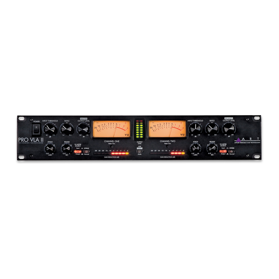
- Page 1 Pro VLA II™ ® PROFESSIONAL TWO CHANNEL VACTROL /TUBE LEVELING AMPLIFIER USER’S GUIDE...
-
Page 2: Important Safety Instructions – Read First
IMPORTANT SAFETY INSTRUCTIONS – READ FIRST This symbol, wherever it appears, This symbol, wherever it appears, alerts alerts you to the presence of uninsulated you to important operating and maintenance dangerous voltage inside the enclosure. Voltage instructions in the accompanying literature. that may be sufficient to constitute a risk of shock. -
Page 3: Table Of Contents
SERVICE ... 13 SPECIFICATIONS... 14 LIST OF FIGURES FIGURE 1 – Channel 1 Controls ... 6 FIGURE 2 – LED Output Meter and Link Switch... 8 FIGURE 3 – Rear Panel ... 10 Pro VLA II ® /TUBE LEVELING AMPLIFIER... -
Page 4: Introduction
- at any price! Unlike typical compressors which use solid state feed-forward circuitry to control level detection, the Pro VLA II is very musical. The nature of its operation is much like the way your eye adjusts to light. Just as your eye transparently adjusts to changes in light, the Pro VLA II... -
Page 5: Analog Audio Connections
Your Pro VLA II was packed with care at the factory. The shipping carton was designed to protect it during initial shipment. Please retain this carton for use in transporting the Pro VLA II when it is not installed in a rack, or in the unlikely event that you need to return your Pro VLA II... -
Page 6: Front Panel Controls And Indicators
If the Pro VLA II fails to power up when the POWER switch is turned on, check to see that its power cord is plugged into an active outlet. If the unit still fails to operate properly, turn it off and unplug it. Then consult your dealer or the ART Customer Service Department. -
Page 7: Figure 1 – Channel 1 Controls
Output Level Control The OUTPUT LEVEL control serves two functions. The CH1 knob always controls the output level of CH1, but can also serve as a “MASTER” output level when the Link Mode is active. The fully counter-clockwise position of the knob mutes the output. The CH2 OUTPUT LEVEL control operates as a standard CH2 level control or as a “BALANCE”... -
Page 8: Gain Reduction Led Meter
VU Meter The input or output levels of the Pro VLA II can be monitored by the analog VU meter. The VU METER switch selects the source of the audio for this meter. The ballistics characteristic of the meter provides an accurate indication of the average signal level. -
Page 9: Figure 2 – Led Output Meter And Link Switch
“-10” mode, this level becomes +6dBu. The Link Switch The two channels of the Pro VLA II can be configured for stereo operation by depressing the LINK switch. Link Mode ties the output attenuation of both channels together onto the CH1 OUTPUT LEVEL knob, and moves all control over “Attack”... -
Page 10: Balanced Inputs
The inputs are designed for use with line level signals ranging from –30dBm to +20dBm. While it is possible to plug an instrument directly into the Pro VLA II™, it is desirable to run the instrument into a preamp ahead of the Pro VLA II™. -
Page 11: Figure 3 – Rear Panel
Balanced Outputs The analog output of the Pro VLA II™ is available on both a 1/4” TRS balanced jack and an XLR jack. This output is active pseudo balanced. The output has a 100 Ohm impedance into a balanced or unbalanced load. -
Page 12: Vocal And Instrument Leveling
Compressor/ Limiter The main application of the Pro VLA II™ is to control the dynamic range of an audio signal. Plug a line level (post preamplifier or other gain stage) source into either input, and set the threshold and output controls to provide the desired amount of compression to the input signal. -
Page 13: Warranty Information
This warranty is void if the serial number is altered, defaced, or removed. ART reserves the right to make changes in design or make additions to or improvements upon this product without any obligation to install the same on products previously manufactured. -
Page 14: Service
2) If you believe the ART unit is at fault, go to www.artproaudio.com. You may contact Customer Service for more assistance, or directly request a Return Authorization for service in the “resources”... -
Page 15: Specifications
Note: 0 dBu = 0.775 VRMS, 0 dBV = 1 VRMS ART maintains a policy of constant product improvement. ART reserves the right to make changes in design, or make additions to, or improvements upon, this product without any obligation to install same on products previously manufactured. Therefore, specifications are subject to change without notice. - Page 16 www.artproaudio.com E-mail: support@artproaudio.com © 2007 Applied Research & Technology 213-5004-100 e...
Need help?
Do you have a question about the Pro VLA II and is the answer not in the manual?
Questions and answers