Table of Contents
Advertisement
Quick Links
SERVICE MANUAL
Ver 1.0 2002. 09
Sony Corporation
9-874-185-01
2002I1600-1
Personal Audio Company
© 2002.09
Published by Sony Engineering Corporation
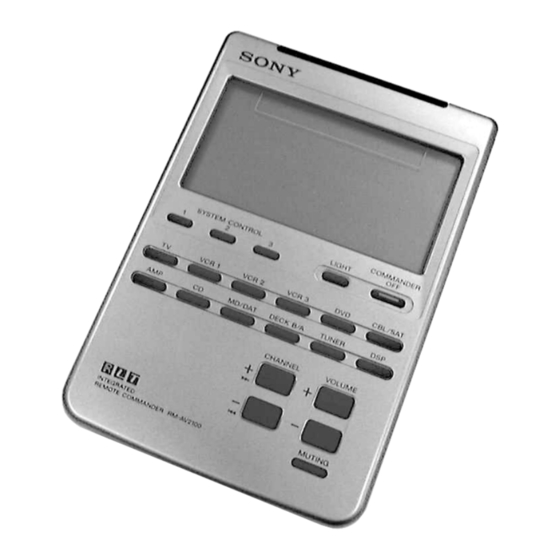
RM-AV2100B
SPECIFICATIONS
Operating distance
Approx. 10 meters (32.8 ft.) (varies
depending on components of different
manufacturers)
Power requirements
Remote control and backlight : Four size
AA (R6) batteries
Battery life
Apporox. 5 months (varies depending on
frequency of use)
Approx. 120 × 175 × 45 mm (w × h × d)
Dimensions
× 7 × 1
(4
3
/
4
Mass
290g (10.22 oz.) (not including batteries)
Design and specifications are subject to change without notice.
INTEGRATED REMOTE COMMANDER
13
/
in.)
16
US Model
Advertisement
Table of Contents

Related Manuals for Sony RM-AV2100B


Summary of Contents for Sony RM-AV2100B
- Page 1 Approx. 120 × 175 × 45 mm (w × h × d) Dimensions × 7 × 1 in.) Mass 290g (10.22 oz.) (not including batteries) Design and specifications are subject to change without notice. INTEGRATED REMOTE COMMANDER Sony Corporation 9-874-185-01 2002I1600-1 Personal Audio Company © 2002.09 Published by Sony Engineering Corporation...
-
Page 2: Table Of Contents
RM-AV2100B TABLE OF CONTENTS 1. GENERAL ·········································································· 3 2. DISASSEMBLY ································································ 4 2-1. Case (Lower) ·································································· 4 2-2. MAIN Board ··································································· 4 3. TEST MODE ······································································ 5 4. DIAGRAMS ········································································ 7 4-1. Printed Wiring Board – Main Section – ························· 7 4-2. -
Page 3: General
RM-AV2100B SECTION 1 This section is extracted from GENERAL instruction manual. 5 COMMANDER OFF button Location and Function Turns the power of the Commander off. of Controls 6 Component Select buttons Selects the component to control. 7 VOLUME +/– buttons* (page 14, 22) Adjust the volume. -
Page 4: Disassembly
RM-AV2100B SECTION 2 DISASSEMBLY Note: Follow the disassembly procedure in the numerical order given. 2-1. Case (Lower) case (upper) claw claw claw two screws (+KTP2 ×4 ) claw case (lower) case (upper) claw claw × 6 battery lid claw two screws (+KTP2 ×4 ) -
Page 5: Test Mode
RM-AV2100B SECTION 3 TEST MODE TEST Mode (Operation Check) LCD touch-key block COMMANDER OFF Preform the following operation checks using the TEST Mode before starting the repair works. CHANNEL + 1. All Keys Operation Check VOLUME + Connection Method :... - Page 6 RM-AV2100B 2. S-RAM (Learning Function) Operation Check Connection Method : Regulated power supply CHANNEL– (+6V constant voltage output) VOLUME– – 1) While pressing the VOLUME – key and the CHANNEL– key, ture ON the main power of the regulated power supply (DC +6V).
-
Page 7: Diagrams
RM-AV2100B SECTION 4 DIAGRAMS 4-1. Printed Wiring Board – Main Section – MAIN BOARD (CONDUCTOR SIDE) MAIN BOARD MAIN BOARD (COMPONENT SIDE) (COMPONENT SIDE) TTP (40KEY) • Semiconductor Location Ref. No. Location B-10 E-10 TO O EL L 1 D-10... -
Page 8: Schematic Diagram - Main Section
RM-AV2100B 4-2. Schematic Diagram – Main Section – • See page 9 for IC Pin Function Description. TP6V (40KEY) TOTAL CURRENT POWER OFF: 0.12mA LIGHT OFF: 0.17mA REG. LIGHT ON: 52.0mA RH5RE50AA 4.7k 2SB709 2SD601 DRY BATTERY (DATA IN) BUFFER BUFFER SYZE"AA"... -
Page 9: Ic Pin Function Description
RM-AV2100B 4-3. IC Pin Function Description • IC1 (µPD780308024) (System Control) Pin No. Pin Name Pin Description P26,27 Segment signal output terminal. Serial input. Serial output. Asynchronous serial clock. — Internally connected. Crystal.(Main system clock) Crystal.(Main system clock) — Power supply. -
Page 10: Exploded Views
RM-AV2100B SECTION 5 EXPLODED VIEWS NOTE: • -XX, -X mean standardized parts, so they may • The mechanical parts with no reference number have some differences from the original one. in the exploded views are not supplied. • Items marked “*” are not stocked since they •... -
Page 11: Electrical Parts List
RM-AV2100B SECTION 6 MAIN ELECTRICAL PARTS LIST NOTE: • Due to standardization, replacements in the • CAPACITORS: • SEMICONDUCTORS uF: µF In each case, u: µ, for example: parts list may be different from the parts uA...: µA... , uPA... , µPA... , specified in the diagrams or the components •... - Page 12 RM-AV2100B MAIN Ref. No. Part No. Description Remarks Ref. No. Part No. Description Remarks 1-216-057-00 RES, CHIP 2.2K 5.00% 1/10W MISCELLANEOUS 1-216-017-91 RES, CHIP 5.00% 1/10W ************** 1-216-041-00 RES, CHIP 5.00% 1/10W 1-216-041-00 RES, CHIP 5.00% 1/10W 9-880-056-01 TTP 1-247-302-11 RES, CHIP 5.00% 1/4W...
- Page 13 RM-AV2100B MEMO...
- Page 14 RM-AV2100B REVISION HISTORY Clicking the version allows you to jump to the revised page. Also, clicking the version at the upper right on the revised page allows you to jump to the next revised page. Ver. Date Description of Revision...
Need help?
Do you have a question about the RM-AV2100B and is the answer not in the manual?
Questions and answers