Table of Contents
Advertisement
Quick Links
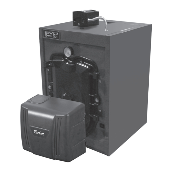
Installation, Operating and Service Instructions for
EMP
• EMP224E
Manual Contents
Pre-installation . . . . . . . . . . . . . . . . . . . . . . . . . . 7
Packaged Boiler Assy . - Trim . . . . . . . . . . . . . . 10
Water Boiler Piping . . . . . . . . . . . . . . . . . . . . . 18
Natural Draft Venting . . . . . . . . . . . . . . . . . . . . 21
Direct Venting / Air Intake Piping . . . . . . . . . . 25
Electrical . . . . . . . . . . . . . . . . . . . . . . . . . . . . . . 32
Oil Piping . . . . . . . . . . . . . . . . . . . . . . . . . . . . . 35
System Start-Up . . . . . . . . . . . . . . . . . . . . . . . . 37
Operation . . . . . . . . . . . . . . . . . . . . . . . . . . . . . 44
Maintenance and Service Instructions . . . . . 49
Boiler Cleaning . . . . . . . . . . . . . . . . . . . . . . . . 51
Troubleshooting . . . . . . . . . . . . . . . . . . . . . . . . 53
Service Parts . . . . . . . . . . . . . . . . . . . . . . . . . . 58
Burner Specifications . . . . . . . . . . . . . . . . . . . 70
As an ENERGY STAR
®
has determined that the EMP series meet the
ENERGY STAR
guidelines for energy efficiency
®
established by the United States Environmental
Protection Agency (EPA).
TO THE INSTALLER:
Affix these instructions adjacent to boiler.
TO THE CONSUMER:
Retain these instructions for future reference.
109529-03 - 11/19
Page
Partner, U.S. Boiler Company
• High Efficiency
• Oil-Fired, 3-Pass
• Water Boiler
• Natural Draft or Direct Vent
(140E thru 224E)
9700609
Advertisement
Table of Contents

Related Manuals for U.S. Boiler Company EMP Series


Summary of Contents for U.S. Boiler Company EMP Series
-
Page 1: Table Of Contents
Burner Specifications . . . . . . . . . . . . . . . . . . . 70 As an ENERGY STAR Partner, U.S. Boiler Company ® has determined that the EMP series meet the ENERGY STAR guidelines for energy efficiency ®... - Page 2 Installation & Service Manual IMPORTANT INFORMATION - READ CAREFULLY All boilers must be installed in accordance with National, State and Local Plumbing, Heating and Electrical Codes and the regulations of the serving utilities . These Codes and Regulations may differ from this instruction manual .
- Page 3 Installation & Service Manual DANGER DO NOT store or use gasoline or other flammable vapors or liquids in the vicinity of this or any other appliance. WARNING Improper installation, adjustment, alteration, service or maintenance can cause property damage, personal injury or loss of life. Failure to follow all instructions in the proper order can cause personal injury or death. Read and understand all instructions, including all those contained in component manufacturers manuals which are provided with the boiler before installing, starting-up, operating, maintaining or servicing this boiler.
- Page 4 Installation & Service Manual WARNING This boiler contains very hot water under high pressure. DO NOT unscrew any pipe fittings nor attempt to disconnect any components of this boiler without positively assuring the water is cool and has no pressure. Always wear protective clothing and equipment when installing, starting up or servicing this boiler to prevent scald injuries.
- Page 5 Installation & Service Manual 109529-03 - 11/19...
-
Page 6: Models
Installation & Service Manual Table 1A: Dimensional Data (see Figure 1) Dimensions See Figure 1 Heat Transfer Actual Boiler Model Water Content Surface Area - Shipping - Gallons “A” “B” “C” Sq. Ft. Weight (LB.) EMP84E/115E 16-5/8” 24” 5” 7.70 13.29 EMP140E 22-5/8”... -
Page 7: Pre-Installation
Installation & Service Manual Pre-Installation A . INSPECT SHIPMENT carefully for any signs of • 24” for flueway cleaning (EMP84E - damage. 140E) • 30” for flueway cleaning (EMP182E) 1. All equipment is carefully manufactured, • 36" for flueway cleaning (EMP224E) inspected and packed. - Page 8 Installation & Service Manual Pre-Installation (continued) 3. Determine type of space. Divide Volume by NOTICE: Clearance to venting is for single wall total input of all appliances in space. If the vent pipe. If Type L vent is used, clearance may result is greater than or equal to 50 ft /1000 be reduced to the minimum required by the vent...
- Page 9 Installation & Service Manual Pre-Installation (continued) square inch per 2,000 BTU per hour input of all i. Direct communication with outdoors . equipment in space. Duct cross-sectional area Minimum free area of 1 square inch per shall be same as opening free area. 4,000 BTU per hour input of all equipment in Alternate method for boiler located within space.
-
Page 10: Packaged Boiler Assy . - Trim
Installation & Service Manual Packaged Boiler Assembly - Trim A . REMOVE CRATE . Step 6. Lower pipe handles until front adjustable legs touch floor. If necessary, 1. Remove all fasteners at crate skid. place wooden blocks under front legs 2. - Page 11 Installation & Service Manual Packaged Boiler Assembly - Trim (continued) 1. TO OPEN BURNER SWING DOOR • Lift door off mounting bracket and set aside. (see Figures 4A and 4B). • Remove mounting bracket and Step 1. Loosen but do not remove left side hardware from left side.
- Page 12 Installation & Service Manual Packaged Boiler Assembly - Trim (continued) Figure 4B: Top View - Burner Swing Door Mounted to Cast Iron Block Assembly (Jacket Removed for Clarity) 109529-03 - 11/19...
- Page 13 Installation & Service Manual Packaged Boiler Assembly - Trim (continued) tightening method from right side tap bolt to left side tap bolt to tighten door equally until 3. To close Burner Swing Door (see Figures 4A sealed without applying excessive torque. and 4B): Never tighten left side flange bolt first or Step 1.
- Page 14 Installation & Service Manual Packaged Boiler Assembly - Trim (continued) NPT upper rear tapping on rear section. a. By design, cast bars on front section between Thread 2" NPT x 1-1/2" Reducing Elbow the combustion chamber and between the left onto 2"...
- Page 15 Installation & Service Manual Packaged Boiler Assembly - Trim (continued) Step c. Pipe discharge of relief valve as Tighten nipple and tee into 1-1/4" NPT lower shown in Figures 9A and 9B. Installation rear tapping or rear section until joints are of the relief valve must be consistent water tight for desired position.
- Page 16 Installation & Service Manual Packaged Boiler Assembly - Trim (continued) • Model EMP84 - To install flueway baffle CAUTION in 2 pass on left side of boiler, hold These baffles will generate higher efficiencies baffle with word "Left" readable at the and lower stack temperatures.
- Page 17 Installation & Service Manual Packaged Boiler Assembly - Trim (continued) • Models EMP140E, EMP182E and CAUTION EMP224E - To install flueway baffle in Do not install burner without gasket. pass flueway on left side of boiler, hold baffle with word "Left" readable Step c.
-
Page 18: Water Boiler Piping
Installation & Service Manual Water Boiler Piping Table 4: Minimum Flow Rate NOTICE: Failure to pipe boiler as specified in this manual may result in excessive system noise. Boiler Model No. Flow Rate (Gal / Min) A . EVALUATE THE EXISTING WATER EMP84E SYSTEM . - Page 19 Installation & Service Manual Water Boiler Piping (continued) 109529-03 - 11/19...
- Page 20 Installation & Service Manual Water Boiler Piping (continued) 109529-03 - 11/19...
-
Page 21: Natural Draft Venting
Installation & Service Manual Natural Draft Venting (All Boiler Models) WARNING Vent this boiler according to these supplemental instructions. Failure to do so may cause products of combustion to enter the home resulting in severe property damage, personal injury or death. •... - Page 22 Installation & Service Manual Natural Draft Venting (continued) 5. Draft Regulator – the draft regulator supplied with the boiler (or equivalent) must be used with this appliance. Refer to Figures 10 and 11. Figure 10: Recommended Vent Pipe Arrangement and Chimney Requirements Figure 11: Proper and Improper Locations of Draft Regulator 109529-03 - 11/19...
- Page 23 Installation & Service Manual Natural Draft Venting (continued) B . CHIMNEY CONNECTOR 2. Minimum Draft at Breech (Canopy) – The draft induced by a chimney must create at least a 1. A chimney connector (vent pipe) is used to pressure of 0 (zero) inches water column (“ w.c.) connect the boiler to the base of the chimney.
- Page 24 Installation & Service Manual Natural Draft Venting (continued) 2. NFPA 31 and CSA B139 have information to E . MINIMUM CLEARANCES help the installer make an appropriate choice See Figure 2A for details regarding clearances to of venting materials. In some cases a chimney combustibles for the boiler.
-
Page 25: Direct Venting / Air Intake Piping
Installation & Service Manual Direct Venting / Air Intake Piping (Boiler Models EMP140E Thru 224E Only) A . GENERAL GUIDELINES WARNING 1. Direct Vent system must be installed in accordance This venting system must be installed by a with these instructions and applicable provisions qualified installer (an individual who has been of local building codes. - Page 26 Installation & Service Manual Direct Venting / Air Intake Piping (continued) Table 5: Wall Cutout Dimensions c. Not less than 1 ft from any door, window or gravity air inlet. Boiler Model Direct Vent Conversion "L" Dimension d. Not less than 7 ft above grade when located Kit Part No.
- Page 27 Installation & Service Manual Direct Venting / Air Intake Piping (continued) 1. The venting system (vent pipe and all connectors) shall be installed in accordance with the applicable provisions of any local codes, and, in United States, requirements of NFPA 31- Standard for the Installation of Oil-Burning Equipment and NFPA 211 Standard for Chimney, Fireplaces, Vents and Solid Fuel-Burning Appliances, latest editions.
- Page 28 Installation & Service Manual Direct Venting / Air Intake Piping (continued) Table 6: Flex Vent / Vent Termination Pipe Diameters Vent Hood Flex Oil Vent Pipe Boiler Flue Outlet * Flue Outlet Collar to Boiler Model No. Inner Pipe Inner Pipe Diameter Collar OD (Inch) Vent Pipe Adapter (Inch) Diameter (Inch)
- Page 29 Installation & Service Manual Direct Venting / Air Intake Piping (continued) 6. Remove any oil and grease from the end of F . CONNECTING FLEX OIL VENT PIPE TO vent termination inner pipe, and, from the end APPLIANCE ADAPTER AND DIRECT VENT of the appliance adapter.
- Page 30 Installation & Service Manual Direct Venting / Air Intake Piping (continued) WARNING DO NOT reduce size of air intake pipe. 3. Start at burner and work towards Direct Vent termination. 4. Remove burner cover. Loosen two screws securing outside air duct bracket to burner cover mounting plate.
- Page 31 Installation & Service Manual Direct Venting / Air Intake Piping (continued) 12. Assemble the vacuum relief valve balance weight 14. Install remainder of air intake piping to Direct onto the gate. Refer to the vacuum relief valve Vent Termination air intake collar, securing manufacturer’s instructions for details.
-
Page 32: Electrical
Installation & Service Manual Electrical DANGER Positively assure all electrical connections are unpowered before attempting installation or service of electrical components or connections of the boiler or building. Lock out all electrical boxes with padlock once power is turned off. WARNING Failure to properly wire electrical connections to the boiler may result in serious physical harm. - Page 33 Installation & Service Manual Electrical (continued) 109529-03 - 11/19...
- Page 34 Installation & Service Manual Electrical (continued) Figure 24: Schematic Wiring Diagram, Water Boiler 109529-03 - 11/19...
-
Page 35: Oil Piping
Installation & Service Manual Oil Piping A . GENERAL NOTICE: Some jurisdictions require the use of a fusible shutoff valve at the tank and/or the burner. 1. Use flexible oil line(s) so the burner swing door In addition, some jurisdictions require the use of a can be opened without disconnecting the oil fusible electrical interlock with the burner circuit. - Page 36 Installation & Service Manual Oil Piping (continued) 3. Under no circumstances is a manual shutoff C . TWO PIPE OIL LINES valve to be located on the return line of a two 1. For two piped systems, where more lift pipe system.
-
Page 37: System Start-Up
Installation & Service Manual System Start-Up WARNING All boilers equipped with burner swing door have a potential hazard which can cause severe property damage, personal injury or loss of life if ignored. Before opening swing door, turn off service switch to boiler to prevent accidental firing of burner outside the combustion chamber. - Page 38 Installation & Service Manual System Start-Up (continued) b. Verify the desired nozzle; refer to Table 9B 2. PRESS RED RESET BUTTON on burner at the rear of this manual, for proper nozzle. primary control, hold for ten (10) seconds and The nozzle must be securely installed to release to reset the control.
- Page 39 Installation & Service Manual System Start-Up (continued) 109529-03 - 11/19...
- Page 40 Installation & Service Manual System Start-Up (continued) which matches a value shown in Table 10 for a particular boiler/burner model. The zero calibration has been factory set; the upper left acorn nut locks retention head at “0” position. If the zero calibration has to be reset, follow the adjustment procedure, outlined at “Prepare Burner &...
- Page 41 Installation & Service Manual System Start-Up (continued) Run the burner for a short period of time. Shut the burner off. The pressure should F . START OIL BURNER . drop and hold. 1. Open vent fitting on fuel pump. d. Turn "OFF" the burner. Remove the 2.
- Page 42 Installation & Service Manual System Start-Up (continued) Beckett NX Burners is shown on the oil primary display along with the time left on the Trial for Ignition a. Move the Head/Air Setting forward or back (TFI). Pressing the up arrow button adds one position at a time to optimize the smoke a minute to the TFI time for a maximum of and CO...
- Page 43 Installation & Service Manual System Start-Up (continued) WARNING • Check contacts between ignitor and the Cad Cell Jumper must be removed after this electrodes. check. • Check the oil pump pressure. • Device tries to restart system after • Check the piping to the oil tank. approximately 60 seconds.
-
Page 44: Operation
Installation & Service Manual Operating A. Setting the High Limit: The high limit is factory set in the boiler from a previous run cycle at 190oF. To adjust, turn the HI TEMP Dial A until to the heating zone that is now calling. The the desired setting is displayed. - Page 45 Installation & Service Manual Operating (continued) WARNING: DO NOT ADD WATER UNTIL THE d. Reset LO TEMP and HI TEMP settings to desired temperatures. BOILER HAS FULLY COOLED . To activate Manual Reset LWCO mode Setting the Well Type (Elctro-Well vs. a.
- Page 46 Installation & Service Manual Operating (continued) Default Dial Setting Feature Options Description Setting Purge Inactive Thermal Pre-Pruge Purge Active Degrees Fahrenheit Fahrenheit or Celsius Degree Celcius LWCO Manual or Automatic Reset Automatic Reset Manual Reset Circulator operation on TT call only Circulator Options Circulator operation on ZC/ZR call only Circulator operation on call from either...
- Page 47 Installation & Service Manual Operating (continued) LWCO TEST LCO WARNING The red Low Water light should illuminate and the Allow the boiler to fully cool before adding water. burner circuit (B1 and B2) should de-energize. NOTE: The control must be installed with a Hydrolevel e.
- Page 48 Installation & Service Manual Operating (continued) Important Product Safety Information: Refractory Ceramic Fiber Product WARNING Some boiler components use materials that contain refractory ceramic fibers (RCF). RCF has been classified as a possible human carcinogen. When exposed to elevated temperatures, RCF may change into crystalline silica, a known carcinogen.
-
Page 49: Maintenance And Service Instructions
Installation & Service Manual Maintenance and Service Instructions 4. Make pH or Alkalinity Test. A . B O I L E R A N D S Y S T E M C L E A N I N G After boiler and system have been cleaned and INSTRUCTIONS TROUBLE FREE... - Page 50 Installation & Service Manual Maintenance and Service Instructions (continued) C . ATTENTION TO BOILER WHILE NOT IN OPERATION . NOTICE: If boiler is not used during winter time, it must be fully drained to prevent freeze damage. 1. Spray inside surfaces with light lubricating or crankcase oil using gun with extended stem so as to reach all corners.
-
Page 51: Boiler Cleaning
Installation & Service Manual Boiler Cleaning WARNING All boiler cleaning must be completed with burner service switch turned off. Boilers equipped with burner swing door have a potential hazard which can cause severe property damage, personal injury or loss of life if ignored. - Page 52 Installation & Service Manual Boiler Cleaning (continued) Figure 35: Cleaning of Boiler Flueways WARNING (Natural Draft Only) The boiler must be connected to an approved chimney in good condition. Serious property damage could result if the boiler is connected to a dirty or inadequate chimney. The interior of the chimney flue must be inspected and cleaned before the start of the heating season and should be inspected periodically throughout the heating season for any obstructions.
-
Page 53: Troubleshooting
Installation & Service Manual Troubleshooting the flame and causes smoke and unburned fuel A . COMBUSTION to pass out of the combustion chamber and clog 1. NOZZLES — Although the nozzle is a relatively the flueways of the boiler. inexpensive device, its function is critical to the successful operation of the oil burner. - Page 54 Installation & Service Manual Troubleshooting (continued) 2. Burner (control) will light, then shut down after NOTICE: If flame is not established within 15 a short time, then restart after one (1) minute. seconds of oil valve actuation (known as Trial a.
- Page 55 Installation & Service Manual Troubleshooting (continued) Burner Will Not Fire See Flow Chart 1 Burner Will Not Shut See Flow Chart 2 Down Temperature Display Under normal operation, boiler temperature will continue to rise after the control shuts off the burner. Exceeds High Limit This condition, known as “thermal stacking”...
- Page 56 Installation & Service Manual Troubleshooting (continued) Troubleshooting Flow Chart 1 - Burner Will Not Fire Troubleshooting Flow Chart 1 – Burner Will Not Fire The Control is The Thermal Pre-Purge feature holds off the burner until the Does the Purging Latent control determines if the latent heat in the boiler can satisfy Display Read Heat from the...
- Page 57 Installation & Service Manual Troubleshooting (continued) Troubleshooting Flow Chart 1 - Burner Will Not Shut Down Troubleshooting Flow Chart 2 – Burner Will Not Shut Down Is the The Control is Red LED (LOW Sensing WATER) On? Low Water. WARNING! TURN OFF POWER TO BURNER IMMEDIATELY! CAUTION –...
-
Page 58: Service Parts
Installation & Service Manual Service Parts 109529-03 - 11/19... - Page 59 Installation & Service Manual Service Parts (continued) Item No. Description Part No. EMP84E EMP115E EMP140E EMP182E EMP224E 109554-02 Block Assembly 109554-03 Includes: Block Assembly and 109554-04 Smoke Box 109554-05 Smoke Box Includes: 109555-01 Sealant and Hardware Burner Swing Door 109556-01 Assembly Includes: Hinge and 109557-01...
- Page 60 Installation & Service Manual Service Parts (continued) 109529-03 - 11/19...
- Page 61 Installation & Service Manual Service Parts (continued) Item Description Part No. EMP84E EMP115E EMP140E EMP182E EMP224E 109552-02 109552-03 Complete Jacket Carton Includes: Labels and Hardware 109552-04 109552-05 109553-02 109553-03 Wrap Around Insulation 109553-04 109553-05 Temperature & Pressure Gauge 105894-01 109564-01 Control Assembly 109565-01 Electro-Well , 1/2"...
- Page 62 Installation & Service Manual Service Parts (continued) Item No. Description Part Number EMP84E EMP115E EMP140E EMP182E EMP224E 104506-02 104507-02 Natural Draft 104508-03 104509-04 Beckett 104510-05 103896-03 Direct Vent 103897-04 103898-05 110109-02 Shown 110110-02 Carlin Natural Draft 110111-03 110112-04 110113-05 Honeywell 103880-01 R7284P1080 Primary...
- Page 63 Installation & Service Manual Service Parts (continued) Item No. Description Part No. EMP140E EMP182E EMP224E Direct Vent Kits and Parts Direct Vent Conversion Kit, 5-6 102130-02 Direct Vent Conversion Kit, 6-7 102130-03 Appliance Adapter, FDVS, 5-6 100234-02 Appliance Adapter, FDVS, 6-7 100234-03 6"...
- Page 64 Installation & Service Manual Service Parts (continued) 109529-03 - 11/19...
- Page 65 Installation & Service Manual Service Parts (continued) BECKETT AFG OIL BURNER PART NOS . FOR EMP SERIES BOILERS NATURAL DRAFT APPLICATIONS NOTE: When ordering parts always give the serial and model numbers shown on the boiler and burner. Also provide the name of the part(s) and part number as listed below.
- Page 66 Installation & Service Manual Service Parts (continued) 109529-03 - 11/19...
- Page 67 Installation & Service Manual Service Parts (continued) BECKETT NX OIL BURNER PART NOS . FOR EMP SERIES BOILERS DIRECT VENT APPLICATIONS NOTE: When ordering parts always give the serial and model numbers shown on the boiler and burner. Also provide the name of the part(s) and part number as listed below.
- Page 68 Service Parts (continued) CARLIN OIL BURNER PART NUMBERS FOR EMP SERIES BOILERS NOTE: When ordering parts always give the serial and model numbers shown on the boiler and burner. Refer to Installation and Operating Instructions for Packaged Heating/Burner Units, Carlin Elite EZ-LF and EZ-66 Oil Burners (Form CCT-569A) for an exploded view of the burner and a list of spare parts.
- Page 69 Installation & Service Manual Burner Specifications Table 9a: Beckett AFG Burner Specifications - Chimney Vent Baffles Baffles Approx. Approx. Burner Pump Head Insertion Approx. Baffle Stack Temp. Boiler Burner Breech Approx. Approx. Input Nozzle Shutter Band Pressure Type Depth Shipped Location Increase Model...
-
Page 70: Burner Specifications
Installation & Service Manual Burner Specifications (continued) Table 10: Beckett NX Burner SPECIFICATIONS - Direct Vent Baffles Baffles Baffles Baffles OUT Approx. Stack Burner Head /Air Pump Approx. Baffle Minimum Temp. Increase Minimum Minimum Minimum Boiler Model Input Adjustment Nozzle Pressure Shipped Location... - Page 71 Installation & Service Manual SERVICE RECORD DATE SERVICE PERFORMED __________________________________________________________________________________________________ __________________________________________________________________________________________________ __________________________________________________________________________________________________ __________________________________________________________________________________________________ __________________________________________________________________________________________________ __________________________________________________________________________________________________ __________________________________________________________________________________________________ __________________________________________________________________________________________________ __________________________________________________________________________________________________ __________________________________________________________________________________________________ __________________________________________________________________________________________________ __________________________________________________________________________________________________ __________________________________________________________________________________________________ __________________________________________________________________________________________________ __________________________________________________________________________________________________ __________________________________________________________________________________________________ __________________________________________________________________________________________________ __________________________________________________________________________________________________ __________________________________________________________________________________________________ __________________________________________________________________________________________________ __________________________________________________________________________________________________ __________________________________________________________________________________________________ __________________________________________________________________________________________________ __________________________________________________________________________________________________ __________________________________________________________________________________________________ __________________________________________________________________________________________________ __________________________________________________________________________________________________ __________________________________________________________________________________________________ __________________________________________________________________________________________________ __________________________________________________________________________________________________ __________________________________________________________________________________________________ __________________________________________________________________________________________________ __________________________________________________________________________________________________ __________________________________________________________________________________________________...
- Page 72 Installation & Service Manual U.S. Boiler Company, Inc. P.O. Box 3020 Lancaster, PA 17604 1-888-432-8887 www.usboiler.net 109529-03 - 11/19...
Need help?
Do you have a question about the EMP Series and is the answer not in the manual?
Questions and answers