Table of Contents
Advertisement
Advertisement
Table of Contents

Related Manuals for Samil Power SolarLake 12000TL-PM


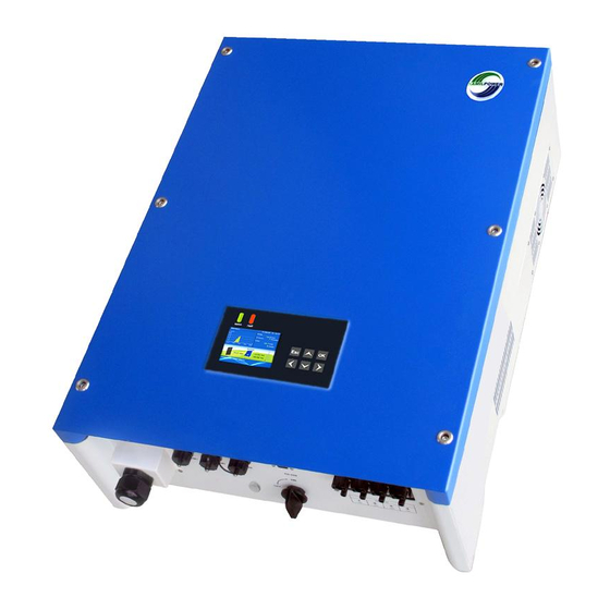
Summary of Contents for Samil Power SolarLake 12000TL-PM
-
Page 2: Table Of Contents
Table of Contents About this Installation Guide ..2 AC- and DC-Connection ....34 Safety Symbols....... 4 Starting the Inverter ...... 44 General Safety Requirements ..6 Commissioning ......46 Intended Use ........8 ....48 Inverter Function......14 Parallel Connection of PV-Ports ... 56 Labels and Markings on Opening the Inverter ..... - Page 3 Indice dei contenuti Informazioni sulle presenti istruzioni Collegamento AC / Collegamento DC .34 ..2 ..34 per l’installazione ......2 Avviare l’inverter ......44 Güvenlik Simgeleri......4 ....44 Simboli di sicurezza ......4 Messa in funzione......49 ....6 Devreye Alma .......
-
Page 4: About This Installation Guide
About this Installation Guide This installation guide describes the Terms: SolarLake 12000TL-PM safe installation of the inverters listed Installer Max. DC-Power 12500 W on the left. in charge of the Max. AC-Power 12000 W Target group: installation Supplier Company the product... - Page 5 Informazioni sulle presenti istruzioni per l’installazione Le presenti istruzioni di installazione Termini: descrivono l’installazione sicura degli Installatore inverter elencati a sinistra. esegue l'installazione. Gruppo di destinazione: Hedef grup: Fornitore Azienda da cui è stato acquistato il prodotto. Produttore: Üretici: Inverter Inverter fotovoltaico No.6, Xuefengshan Road, No.6, Xuefengshan Road,...
-
Page 6: Safety Symbols
Safety Symbols Life threatening voltages are Countermeasures that must processed inside the inverter. be taken in order to avoid the Hazardous situations that can lead to hazardous situation are indicated with death or serious injuries are indicated with the “WARNING” symbol (1) on “This is an example how to avoid a the left. - Page 7 Simboli di sicurezza Güvenlik Simgeleri Nell’inverter vengono utilizzate Contromisure per prevenire tensioni mortali. la situazione pericolosa sono Situazioni pericolose che possono causare morte o lesioni gravi “Questo è un esempio di come sebep olabilecek tehlikeli durumlar sono contrassegnate dal simbolo prevenire una situazione soldaki “UYARI”...
-
Page 8: General Safety Requirements
General Safety Requirements 1. WARNING! Danger of electric 4. 2 people are required for shock! lifting and transporting. Read Installation Guide WARNING! Danger of electric carefully. Follow all instructions. Never modify the inverter unless 2. Contact your supplier when you explicitly instructed to do so by the have questions. - Page 9 Indicazioni di sicurezza fondamentali 1. AVVERTENZA! Pericolo dovuto 4. Il sollevamento e il a scossa elettrica! trasporto del dispositivo tehlikesi! Leggere attentamente le deve essere effettuato da 2 istruzioni di installazione. persone. tehlikesi! Seguire tutte le istruzioni. AVVERTENZA! Pericolo dovuto a yerine getiriniz.
-
Page 10: Intended Use
Intended Use The inverter (1) converts DC-power CAUTION! Risk of damaging from the PV-generator (2) to AC- the inverter! power. The AC-power is fed into the Do not connect other DC-power sources (6) such as wind power inverter automatically disconnects systems, hydroelectric generators, (4) from the grid. - Page 11 Utilizzo conforme L’inverter (1) trasforma la potenza L’inverter può essere utilizzato DC del generatore fotovoltaico (2) solo per la potenza DC dei jeneratörlerinden (5) gelen DC in potenza AC. La potenza AC viene generatori fotovoltaici (5). immessa nella rete pubblica (3). CAUTELA! Pericolo di danneggiamento dell’inverter! tehlikesi!
- Page 12 Electrical Safety 1. WARNING! Risk of electric 2. The inverter is not shock! The PV-panels emit a equipped with an internal dangerous DC-voltage when isolation transformer exposed to sunlight. 3. Local regulations and standards can require that an isolation transformer is additionally installed.
- Page 13 Sicurezza elettrica Elektriksel Güvenlik 1. AVVERTENZA! Pericolo dovuto 2. L’inverter non dispone 1. UYARI! a scossa elettrica! I moduli di un trasformatore di tehlikesi! trafosu bulunmaz. fotovoltaici generano tensione DC separazione. modüllerinde tehlikeli bir DC pericolosa quando splende il sole. 3.
- Page 14 DC-Disconnect / RCD 1. Local regulations and standards 2. The inverter is equipped can require that current-breakers with an integrated RCMU are installed on the DC-side. Type B (tested according to EN DC + Contact your utility operator if you 62109-2 / IEC 60755).
- Page 15 Dispositivo di sezionamento DC / RCD 1. Le disposizioni e le normative 2. L’inverter è dotato di una in vigore possono prevedere RCMU integrata del tipo B RCMU (EN 62109-2 / IEC l’impiego di sezionatori dal lato DC. Chiedere al proprio gestore di / IEC 60755).
-
Page 16: Inverter Function
Inverter Function (With String Monitoring) 1. DC-side surge voltage protection 8. AC-side surge voltage (optional) protection (optional) 2. DC-side disconnection switch 9. Digital output port DC1+ (optional) 10. Digital input port DC1 - 3. DC-side insulation monitoring 11. String current monitoring and 4. - Page 17 Funzionamento (con monitoraggio delle stringhe) 1. Protezione da sovratensioni lato 8. Protezione da DC (opzionale) sovratensioni lato AC 2. Sezionatore lato DC (opzionale) (opzionale) 3. Monitoraggio dell’isolamento lato 9. Uscita digitale 10. Ingresso digitale 4. Display, LED di stato, tasti 11.
- Page 18 Inverter Function (Without String Monitoring) 1. DC-side surge voltage protection 8. AC-side surge voltage (optional) protection (optional) 2. DC-side disconnection switch 9. Digital output port DC1+ (optional) 10. Digital input port DC1 - 3. DC-side insulation monitoring 4. Display, status LEDs, buttons DC2+ 5.
- Page 19 Funzionamento (senza monitoraggio delle stringhe) 1. Protezione da sovratensioni lato 8. Protezione da DC (opzionale) sovratensioni lato AC 2. Sezionatore lato DC (opzionale) (opzionale) 3. Monitoraggio dell’isolamento lato 9. Uscita digitale 10. Ingresso digitale 4. Display, LED di stato, tasti 4.
-
Page 20: Labels And Markings On The Inverter
Labels and Markings on the Inverter Symbols on Type Label: Markings and Symbols on General Symbols bottom of Inverter: 1. Ensure proper disposal 7. DC connection area 2. CE-mark 8. Opening for ethernet and RS485 Safety Symbols cables 3. Read documentation! 9. - Page 21 Indicazioni e simboli sull’inverter Simboli sulla targhetta del modello: Contrassegni sulla parte Tip etiketi üzerindeki simgeler: Simboli generali inferiore dell’inverter: Genel Simgeler 1. Smaltire conformemente alle 7. Area di collegamento DC 1. Kurallara uygun olarak bertaraf disposizioni 8. Apertura per Ethernet e RS485 edin 2.
-
Page 22: Ports De L'onduleur
Connections on the Inverter 1. PV-plugs (Interters with string monitoring. ports depends on inverter type.) 2. PV-cable glands (Inverters without string monitoring) 3. Opening for RS485-cable and ethernet cable 4. Digital input and digital output cable gland 5. AC-cable gland AC GRID RS485 / LAN Relay... - Page 23 Collegamenti con l’inverter 1. Connettore FV (inverter con monitoraggio delle stringhe). ingressi dipende dal modello. 2. Aperture per cavo FV (inverter inverter) senza monitoraggio delle stringhe) 3. Apertura per cavo Ethernet e RS485 5. AC kablosu rakoru 4. Apertura per ingressi digitali e uscite digitali 5.
-
Page 24: Interface Utilisateur
User Interface 4. OK-Key On = Normal operation, Press OK-key in order to Flashing = Waiting, checking or starting up, Off = Possible failure 2. Red LED Pressing the cursor keys On = Failure, navigates the menu and increases Flashing = Temporary failure, or decreases values. - Page 25 Interfaccia utente 1. LED verde 4. Tasto OK acceso = funzionamento normale Premere il tasto OK per confermare l’inserimento. in corso o in avviamento spento = 5. Tasti del cursore possibile errore Premere i tasti del cursore per 2. LED rosso navigare nel menu e aumentare o acceso = errore diminuire i valori.
-
Page 26: Déballage
Unpacking Proceed as follows: 4. Check all items for visible 1. Check the packaging for damages. damages. 5. Contact your supplier when 2. Contact your supplier in case items are missing or the inverter packaging is damaged. is damaged. Do not install a 3. - Page 27 Disimballaggio Procedere come segue: sia danneggiato. danneggiato. 5. Contattare il proprio fornitore kontrol edin. edin. 2. Contattare il proprio fornitore qualora manchi qualcosa o in qualora l’imballaggio fosse caso di danni. Non utilizzare mai deteriorato. un inverter danneggiato. Conservare la confezione per l’utilizzo la presenza di tutti i componenti.
- Page 28 Scope of Delivery 1. Inverter 10. 9-pin plug (for digital input) 2. Wall mounting bracket 11. DC-terminal clamp (2 x) or 3. Installation kit (screws for wall DC-terminal jumper (2 x) mounting) (Used for parallel connection. 4. RJ45 plug (3 X) Type depends on DC-terminal) 5.
- Page 29 Componenti 1. Inverter 10. Connettore a 9 poli (per 2. Supporto da parete ingressi digitali) 3. Kit di montaggio (viti per supporto 11. Graffa per morsetto DC (2 x) a parete) oppure ponticello per morsetto DC 4. Connettore RJ45 (3 x) (2 x) (Per circuito in parallelo degli 5.
- Page 30 Required Tools The following tools are required for 7. Screwdriver 8. Hammer 1. Crimping tool for DC-plugs 9. Level (e.g. type PV-CZM) 10. Hex key (4 mm) 2. Cable stripping tool for DC-cables (e.g. PV-AZM) 3. Drill 4. Multimeter 5. Open-end spanner kit for DC- plugs (e.g.
- Page 31 Utensili occorrenti Gerekli Aletler Per l’installazione dell’inverter è 7. Cacciavite 7. Tornavida 8. Martello 1. Pinza a crimpare per connettore 9. Livella ad acqua 9. Su terazisi DC (ad es. PV-CZM) 10. Brugola (4 mm) 10. Alyen anahtar (4 mm) es.
-
Page 32: Montage De L'onduleur
Mounting the Inverter Requirements for the installation pages. Proceed as follows: 1. Screw wall mounting bracket to wall. 2. Hang inverter on wall mounting bracket. 3. Check correct position. a padlock. Montage des Wechselrichters Die Bedingungen an den Montageort sind auf den folgenden Seiten aufgeführt. - Page 33 Montaggio dell’inverter Le condizioni relative al luogo di Montaj yerinin gereksinimleri ilerideki montaggio sono riportate nelle pagine sayfalarda verilmektedir. seguenti. Procedere come segue: 1. Avvitare il supporto sulla parete. 2. Appendere l’inverter al supporto a parete. edin. un lucchetto. Montaje del inversor Montar o inversor Las condiciones del lugar de montaje Os requisitos impostos ao local de...
- Page 34 min. 50 cm 5 min. PV Grid-tied Inverter www.samilpower.com SolarLake 7000TL-PM min. DC,max 1000 V DC,MPP 380 - 800 V 11.5 DC,max 50 cm DC,sc AC,r 230/400 V AC,r 7000 W 7000 VA 50 / 60 Hz AC,r AC,max 10 A cos( ): -0.8...
- Page 35 5 min. www.samilpower.com PV Grid-tied Inverter SolarLake 7000TL-PM DC,max 1000 V DC,MPP DC,max 380 - 800 V 11.5 DC,sc 230/400 V AC,r AC,r 7000 W 7000 VA AC,r 50 / 60 Hz AC,max cos( ): -0.8... 10 A 1... +0.8 Protective Class: I Communication...
- Page 36 6 - 16 mm Leitungsverluste unter 1 %. Halten Sie die Impedanz unter 0,2 Ohm. Connexion AC - Conditions préalables SolarLake 12000TL-PM: 4 -16 mm SolarLake 20000TL-PM: 4 -16 mm 1. Utilisez un disjoncteur approprié. 4. Respectez les valeurs SolarLake 15000TL-PM: 4 -16 mm...
- Page 37 Collegamento AC – Condizioni 1. Utilizzare un interruttore 4. Prestare attenzione magnetotermico appropriato. ai valori relativi alle edin. 2. AVVERTENZA! Pericolo dovuto dimensioni dei cavi. AC kablosuna herhangi bir ad incendio! 5. In Francia: utilizzare un 6 - 16 mm Non collegare alcuna utenza al raccordo di PE con una sezione cavo AC.
- Page 38 Connection of the AC Cable WARNING! Risk of electric shock! 5. Remove swivel nut and Deactivate AC-voltage when shove swivel nut over connecting the AC-cable. cable. Proceed as follows: 6. Attach wires to AC-terminal. 0 V ? 1. Disconnect voltage. 7.
- Page 39 Collegare il cavo AC AVVERTENZA! Pericolo dovuto a 5. Svitare il dado di raccordo 5. Rakoru sökün ve kabloya scossa elettrica! e spingere sul cavo. Disattivare la tensione AC prima di 6. Collegare il cavo AC al morsetto 6. AC kablosunu AC klemensine collegare il cavo AC.
- Page 40 DC-Connection - Requirements 1. CAUTION! Risk of damaging the inverter! See page 56. Ensure that the voltage and 5. Cover PV-modules when working < 1000 V on the DC-connection. values. 6. WARNING! Risk of electric 2. Do not connect the + or - poles to shock! ground.
- Page 41 Collegamento DC – Condizioni 1. CAUTELA! Pericolo di 4. Gli ingressi DC possono danneggiamento dell’inverter! essere collegati. Vedere Accertarsi che la tensione e la pagina 56. corrente elettrica siano inferiori 5. Scoprire i moduli fotovoltaici PV modüllerinin üzerlerini örtün. ai valori limite indicati. quando si interviene sul 2.
- Page 42 PV Connection (PV Plugs) Note: Assembly of the PV-plugs is 4. Crimp cable on plug 6 - 7.5 mm only necessary for inverters with contact. string monitoring. 5. Insert plug contact in plug. Pull on WARNING! Risk of electric shock! contact in order to check that the Cover PV-modules when working contact is locked in the plug.
- Page 43 Collegamento FV (connettore FV) Indicazione: il collegamento del 4. Crimpare il contatto sul Bilgi: connettore FV è necessario solo per cavo. inverter con monitoraggio delle stringhe. 5. Spingere il contatto nella spina. AVVERTENZA! Pericolo dovuto a scossa elettrica! sede corretta. Scoprire i moduli fotovoltaici 6.
- Page 44 PV Connection (PV Screw Terminal) Note: The connection of the PV- Proceed as follows: cables to the PV-terminal is only 1. Remove screw on display required for inverters without string board. monitoring. 2. Tilt display board up. WARNING! Risk of electric shock! 3.
- Page 45 Collegamento FV (morsetto a vite FV) Indicazione: il collegamento del cavo Procedere come segue: Bilgi: PV kablosu ve PV klemensi FV al morsetto FV è necessario solo 1. Allentare la vite sul circuito per inverter senza monitoraggio delle stampato con il display. stringhe.
-
Page 46: Starting The Inverter
Starting the Inverter Before starting: Proceed as follows for starting: Make sure DC-switch is “OFF”. 1. Turn DC-switch to “ON”. Make sure AC-switch is “OFF. 2. Turn AC-switch to “ON”. For inverters with integrated string 3. Activate AC-power. The inverter starts operation. In case are connected. - Page 47 Avviare l’inverter Prima dell’avvio: Per l’avvio procedere come segue: gerekenler: spento. 1. Impostare l’interruttore DC su “Acceso”. getirin. spento. 2. Impostare l’interruttore AC su Per gli inverter con monitoraggio “Acceso”. getirin. 3. Accendere la rete AC. che i connettori DC siano collegati. L’inverter inizia a funzionare.
-
Page 48: Commissioning
Commissioning After connecting to AC and DC Specify Date and Time. - - - Date/Time power the inverter presents the screen on the left. SamilPower Co., LTD. Press OK to start 2 0 1 4 commissioning. 987654000 V1.83 V1.83 V1.10 Press OK to start commissioning. - Page 49 Inbetriebnahme Nach Anschluss der AC und Geben Sie Datum und Uhrzeit Datum/Uhrzeit - - - DC Seite präsentiert der ein. Wechselrichter das Fenster links. Drücken Sie OK um zu SamilPower Co., LTD. Drücken sie OK um die bestätigen. 2 0 1 4 Inbetriebnahme zu starten.
- Page 50 Mise en service Une fois les côtés AC et DC Entrez la date et l'heure. - - - Date / heure Appuyez sur OK pour SamilPower Co., LTD. fenêtre de gauche. AAAA 2 0 1 4 démarrer la mise en service. 987654000 V1.83 V1.83...
- Page 51 Messa in funzione Dopo il collegamento del lato AC e Inserire data e ora. Data/ora Premere OK per confermare. a sinistra. SamilPower Co., LTD. AAAA Premere OK per avviare la 2 0 1 4 messa in funzione. 987654000 V1.83 V1.83 V1.10 Press OK to start commissioning.
- Page 52 Puesta en servicio Después de conectar el lado Introduzca fecha y hora. - - - Fecha/hora AC y DC el inversor presenta la SamilPower Co., LTD. ventana izquierda. AAAA Pulse OK para arrancar la 2 0 1 4 puesta en servicio. 987654000 V1.83 V1.83...
- Page 53 Ingebruikneming Na aansluiting van de AC- en DC- Voer de datum en tijd in. Date/Time kant presenteert de omvormer het Druk op OK om te bevestigen. venster links. SamilPower Co., LTD. Druk op OK om de 2 0 1 4 ingebruikneming te starten.
- Page 54 Devreye Alma Tarihi ve saati girin. - - - Date/Time sonra inverterde soldaki ekran SamilPower Co., LTD. görünür. 2 0 1 4 987654000 V1.83 V1.83 V1.10 Press OK to start commissioning. Language End Commissioning English German French DE - VDE 4105 Spanish Press OK to start running Press ESC to back...
- Page 55 Depois de conectar o lado AC e o Introduza a data e a hora. Date/Time lado DC, o inversor apresenta a janela ilustrada do lado esquerdo. SamilPower Co., LTD. Prima OK para iniciar a 2 0 1 4 987654000 V1.83 V1.83 V1.10 Press OK to start commissioning.
- Page 56 Use the SamilPower SolarPower be done in compliance with In general the inverters are connected the utility operator! to a PC (3) with ethernet (1). A router (2) can be used in order to connect SolarPower Browser can be used for several inverters.
- Page 57 Utilizzare il browser SamilPower Essenzialmente gli inverter vengono è consentita solo dietro accordo collegati a un PC (3) con un cavo kablosu (1) üzerinden bir PC’ye con il gestore di rete. Ethernet (1). Si può utilizzare un router (2) per collegare più inverter. Il browser SolarPower può...
-
Page 58: Parallel Connection Of Pv-Ports
Parallel Connection of PV-Ports DC1+ DC1+ DC1+ DC1+ 1. It is possible to connect the two connection inside the input ports in parallel. inverter. DC1 - DC1 - DC1 - DC1 - 2. Install diodes in order to prevent B. When terminal jumper is reverse currents. - Page 59 Collegamento in parallelo degli ingressi 1. Gli ingressi possono essere B. Se viene fornito un collegati in parallelo. 2. Installare i diodi per prevenire il ponticello per il circuito corrente inversa. in parallelo degli ingressi 3. L’inverter è dotato di 2 diversi nell’inverter.
- Page 60 Opening the Inverter Proceed as follows: 4. WARNING! Danger of 1. Ensure that no water will enter electric shock! when the inverter is open. Wait for 5 minutes in order to 2. Disconnect AC-power. Switch AC let internal voltages discharge switch off.
- Page 61 Come aprire l’inverter Procedere come segue: 4. AVVERTENZA! Pericolo 1. Accertarsi che non possa dovuto a scossa tehlikesi! penetrare acqua quando l’inverter elettrica! Dahili gerilimlerin è aperto. Attendere 5 minuti in modo che le tensioni interne bekleyin. l’interruttore AC. possano scaricarsi. 5.
- Page 62 Connections Inside Inverter The inverter is equipped with the Schematic diagrams of 3-NO examples for the connection are available on the following pages. 3-COM extension of the inverter memory and storage of yield data. WARNING! Risk of electric shock! 2-NO 3-NC Only open the inverter as data logger.
- Page 63 Collegamenti nell’inverter L’inverter è dotato delle seguenti Disegni schematici per il collegamento sono disponibili alle pagine seguenti. örnekler verilmektedir. la memoria dell’inverter e per il salvataggio dei dati di rendimento. AVVERTENZA! Pericolo dovuto a scossa elettrica! collegare un datalogger. Aprire l’inverter solo come 3.
- Page 64 Digital Input Ports The inverter is equipped with 6 The digital input ports DI5 and digital input ports (1). The digital DI6 (3) are not activated. The usage input ports DI1 - DI4 can be used for the connection of a ripple control versions.
- Page 65 Ingressi digitali L’inverter è dotato di 6 ingressi Gli ingressi digitali DI5 e DI6 digitali (1). Gli ingressi digitali DI1 (3) non sono attivati. Questi - DI4 possono essere utilizzati per possono essere utilizzati con versioni il collegamento di un ricevitore di segnali di telecomando centralizzato Per dettagli si veda www.
- Page 66 Digital Output The inverter is equipped with 3 digital output ports (relay) (1). The usage is possible with future Check www.SAMILPOWER.com for details. Digitaler Ausgang Der Wechselrichter ist mit 3 digitalen Ausgängen (Relais) (1) ausgerüstet. 3-NO PV1+ PV2+ PV1- PV2- Diese können mit späteren Firmwareversionen benutzt werden.
- Page 67 Uscita digitale L’inverter è dotato di 3 uscite digitali (relè) (1). Questi possono essere utilizzati con Per dettagli si veda www. SAMILPOWER.com. SAMILPOWER.com. Salidas digitales Saída digital El inversor está equipado con 3 O inversor está equipado com 3 salidas digitales (relés) (1). saídas digitais (relés) (1).
- Page 68 Ethernet / RS485 Connection Ethernet: RJ45 LIYCY ≥ 0.14 mm Ethernet Connection: RS485 Connection: Cat 5 / 7 SSTP 1. Put cable through enclosure 1. Put cables through enclosure opening. opening. 2. Connect cable to plug. 2. Connect cables to plugs. Use 3.
- Page 69 Collegamento Ethernet / RS485 Collegamento Ethernet: Collegamento RS485: 1. Inserire il cavo nell’involucro. 1. Kabloyu muhafazaya sokun. 1. Inserire il cavo 1. Kabloyu muhafazaya 2. Collegare il cavo al connettore. nell’involucro. sokun. 3. Introdurre il connettore nella 2. Collegare il cavo al connettore. presa.
- Page 86 Samil Power Software www.SAMILPOWER.com SL12-30TL-PM-IG_10_EU1714...
- Page 87 One-Stop Shopping Samil Power Product Portfolio SolarPond SolarRiver 240 W 1.0 - 5.75 kW SolarLake Accessories 5.5 - 30 kW SolarWatcher 100 SolarWatcher 500 Array Combiner Boxes SL12-30TL-PM-IG_10_EU1714...
Need help?
Do you have a question about the SolarLake 12000TL-PM and is the answer not in the manual?
Questions and answers