Table of Contents
Advertisement
Quick Links
Application
The Temperature and Relative Humidity FX-WRZ Series Wireless Room Sensors are designed to
sense room/zone temperature and transmit wireless temperature control data. Some models also
sense and transmit relative humidity.
In an FX-ZFR Series Wireless Field Bus System application, the sensors communicate with the FX-PC
Controllers through the FX-ZFR18xx Series Router.
In a One-to-One Wireless Room Sensing application, the sensors communicate with an FX-WRZ7860
Wireless Receiver. The FX-WRZ7860 Receiver transfers data to the controller by means of the Sensor
Actuator (SA) communication bus. In a typical application, one FX-WRZ Series Sensor reports to
one FX-WRZ7860 Receiver, but up to five FX-WRZ Series Sensors can be associated with a single FX-
WRZ7860 Receiver for multi-sensor averaging or high/low temperature selection.
FX-WRZ Series sensor models are available with or without an LCD. Depending on the sensor
model, the FX-WRZ Series Sensor can transmit sensed temperature, setpoint temperature, sensed
humidity, and low battery conditions to an associated router or receiver. The FX-WRZ Series Sensors
are designed for indoor, intra-building applications only.
The FX-WRZ Sensors use direct-sequence, spread-spectrum RF technology, and operate on the
2.4 GHz Industrial, Scientific, and Medical (ISM) band. The receiver meets the Institute of Electrical
and Electronics Engineers (IEEE) 802.15.4 standard for low power, low duty cycle RF transmitting
systems.
Important:
Use the FX-WRZ Series Sensors only to provide an input to equipment under normal oper-
ating conditions. Where failure or malfunction of the sensor could lead to personal injury or
property damage to the controlled equipment or other property, additional precautions must
be designed into the control system. Incorporate and maintain other devices, such as super-
visory or alarm systems or safety or limit controls, intended to warn of or protect against fail-
ure or malfunction of the sensor.
North American Emissions Compliance
North American Emissions Compliance
United States
Compliance Statement (Part 15.19)
This device complies with Part 15 of the FCC Rules. Operation is subject to the following two
conditions:
1. This device may not cause harmful interference, and
2. This device must accept any interference received, including interference that may cause
undesired operation.
Warning (Part 15.21)
Changes or modifications not expressly approved by the party responsible for compliance could
void the user's authority to operate the equipment.
Part No. 24-10332-37 Rev. H
2019-03-26
Temperature and Relative Humidity
FX-WRZ Series Wireless Room Sensors
Installation Instructions
*241033237H*
(barcode for factory use only)
FX-WRZTTJ00-0, FX-WRZTTK00-0, FX-WRZTHJ00-0
Advertisement
Table of Contents

Related Manuals for Johnson Controls FX-WRZ Series


Summary of Contents for Johnson Controls FX-WRZ Series
- Page 1 Actuator (SA) communication bus. In a typical application, one FX-WRZ Series Sensor reports to one FX-WRZ7860 Receiver, but up to five FX-WRZ Series Sensors can be associated with a single FX- WRZ7860 Receiver for multi-sensor averaging or high/low temperature selection.
-
Page 2: Installation
Parts included • One FX-WRZ Series Sensor with strips of double-sided adhesive foam tape installed • One DIP switch overlay for a mesh network application using an FX-ZFR18xx Series Router • One DIP switch overlay for a One-to-One application using an FX-WRZ7860 Receiver •... -
Page 3: Special Tools Needed
Location considerations Temperature sensor considerations When locating an FX-WRZ Series Sensor, follow the same best practices used to locate a hard-wired temperature control, sensor, or thermostat: • Mount the sensor on an interior wall where it is easily accessible, at least 1.4 m (55 in.) above the floor, in an area where the temperature is representative of the entire controlled space. - Page 4 Operation. Important: Do not power up the FX-WRZ Series Sensor until a receiver or controller is installed and oper- ating within the same Radio Frequency (RF) range. If this condition is not met, the sensor uses a higher-than-normal battery current as it attempts to find a receiver or controller within range, resulting in reduced battery life.
- Page 5 Can-Do National Tape (Code No. 99116) adhesive foam tape or its equivalent. Preparing the FX-WRZ Series Sensor for operation To prepare the FX-WRZ Series Sensor for operation, and to reinstall the sensor housing on its mounting base: Place the appropriate DIP switch overlay (based on the application) over the DIP switches. See Figure 3 through Figure 5.
- Page 6 DIP switches as indicated. See Commissioning Multiple FX-WRZ Sensors for information on commissioning multiple FX-WRZ Series Sensors in an FX-ZFR Series Wireless Field Bus Sys- tem. a. Set the POWER switch to OFF. b. Set the MODE switch to MESH.
- Page 7 For a One-to-One network application with an FX-WRZ7860 Receiver (Figure 4), set the DIP switches as indicated, ensuring that the AREA and TRANSMITTER ID switches on the FX- WRZ7860 Receiver and the FX-WRZ Series Sensors are set to the same value. a. Set the POWER switch to OFF.
- Page 8 Receiver, press and release the manual occupancy override button to display signal strength. Press and hold the manual occupancy override button on the FX-WRZ Series Sensor (Figure 1) for 5 seconds or more to place the sensor into Rapid Transmit Mode and initiate a signal strength test with the associated FX-ZFR18xx Series Router or FX-WRZ7860 Receiver.
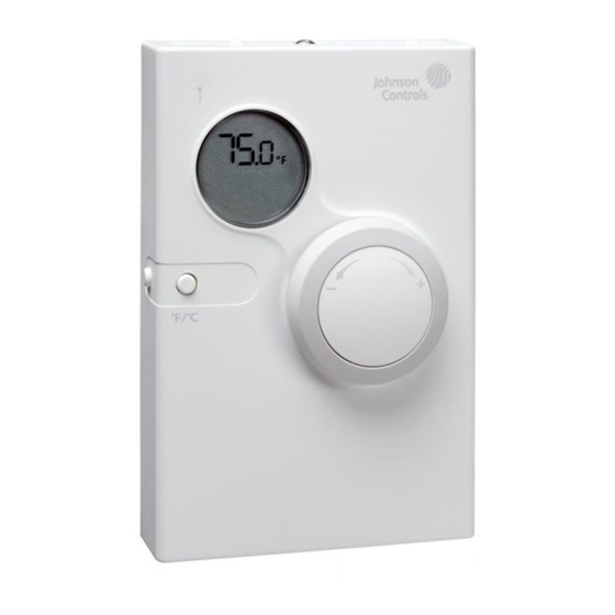
- Page 9 Figure 7: Sensor LCD(FX-WRZTHJ, FX-WRZTTJ, FX-WRZTTK Models) Note: For FX-WRZ Series Sensors with an LCD display, the humidity value may appear as 0.0% when the sensor is joining a network. This condition is transitory and does not transfer to the Building Automation System (BAS).
- Page 10 Commissioning multiple FX-WRZ Sensors Mesh mode You can add up to nine FX-WRZ Series Sensors for each FX-PCG, FX-PCA, or FX-PCV in mesh mode. The Zone DIP switches on the FX-WRZ Sensor relate to the Zone Netsensor (SA Bus device) address configured for the sensor in the Controller Configuration Tool (CCT).
-
Page 11: Repair Information
For a replacement sensor, contact the nearest Johnson Controls representative. Batteries The two AA alkaline batteries supplied with the FX-WRZ Series Sensor typically have a life of 5 years or more. The sensor reports a low battery condition to the receiver or controller, which relays the low battery condition to the system. -
Page 12: Technical Specifications
Table 3: Accessories Ordering Information Code number Description FX-WRZSST-120 Wireless Sensing System Tool: For Use with an FX-WRZ Series Sensor, to Function as a Site Survey Tool for the FX-WRZ7860-0 One-to-One Room Sensing System, or for the FX-ZFR Wireless Field Bus System T-4000-119 Allen-Head Adjustment Tool: 1.6 mm (1/16 in.), 30 Tools for Each Bag... -
Page 13: Points Of Single Contact
The performance specifications are nominal and conform to acceptable industry standard. For application at conditions beyond these specifications, consult the local Johnson Controls office. Johnson Controls shall not be liable for damages resulting from misapplication or misuse of its products. - Page 14 © 2019 Johnson Controls. All rights reserved. All specifications and other information shown were current as of document revision and are subject to change without notice. www.johnsoncontrols.com...
Need help?
Do you have a question about the FX-WRZ Series and is the answer not in the manual?
Questions and answers
We have 84 JC vvt's in our facility. Is the temp setpoint adjustment dial how you would calibrate the settings?
To adjust the temperature setpoint on a Johnson Controls FX-WRZ Series VVT, use the up and down arrow buttons on the face of the network sensor. Press the up arrow to increase the setpoint and the down arrow to decrease it. The new setpoint will stop flashing and become fixed after a few seconds.
This answer is automatically generated